HAL Id: tel-02091135
https://pastel.archives-ouvertes.fr/tel-02091135v2
Submitted on 5 Apr 2019
HAL is a multi-disciplinary open access
archive for the deposit and dissemination of sci-entific research documents, whether they are pub-lished or not. The documents may come from teaching and research institutions in France or abroad, or from public or private research centers.
L’archive ouverte pluridisciplinaire HAL, est destinée au dépôt et à la diffusion de documents scientifiques de niveau recherche, publiés ou non, émanant des établissements d’enseignement et de recherche français ou étrangers, des laboratoires publics ou privés.
plasma wakefields driven by few-cycle laser pulses
Dominykas Gustas
To cite this version:
Dominykas Gustas. High-repetition-rate relativistic electron acceleration in plasma wakefields driven by few-cycle laser pulses. Accelerator Physics [physics.acc-ph]. Université Paris Saclay (COmUE), 2018. English. �NNT : 2018SACLX118�. �tel-02091135v2�
High-repetition-rate relativistic
electron acceleration in plasma
wakefields driven by few-cycle
laser pulses
Thèse de doctorat de l'Université Paris-Saclay préparée à l’École Polytechnique
École doctorale n°572 ondes et matières (EDOM) Spécialité de doctorat: Physique des plasmas
Thèse présentée et soutenue à Palaiseau, le 14 décembre 2018, par
Dominykas Gustas
Composition du Jury :
Patrick Audebert
Directeur de recherche, École Polytechnique, LULI Président
Philippe Balcou
Directeur de recherche, Université de Bordeaux, CELIA Rapporteur
Alexander Thomas
Associate professor, University of Michigan, NERS Rapporteur
Guy Bonnaud
Professeur, INSTN, CEA Examinateur
Marie-Emmanuelle Couprie
Directrice de recherche, SOLEIL synchrotron Examinatrice
Jérôme Faure
Directeur de recherche, École Polytechnique, LOA Directeur de thèse
NNT : 2 0 1 8 S A CL X 1 1 8
Contents
1 Introduction 5
1.1 Context . . . 5
1.2 Objectives . . . 7
1.3 Outline . . . 8
2 Physics of laser wakefield accelerators 9 2.1 Ponderomotive force . . . 10
2.2 Qualitative description . . . 12
2.3 Laser-driven wakefield generation formalism. . . 13
2.4 Accelerator injection schemes . . . 23
2.5 LWFA limiting factors . . . 27
2.6 Plasma effects on laser pulse propagation . . . 30
2.7 Electron bunch propagation . . . 35
2.8 Physics of gas jets . . . 38
3 Experimental tools 43 3.1 Overview of the project . . . 44
3.2 Laser system . . . 46
3.3 Electron beam diagnostics . . . 52
3.4 Target characterisation . . . 57
3.5 Numerical modelling . . . 62
4 Acceleration experiments 65 4.1 MeV electrons at kHz repetition rate . . . 66
4.2 Shocked nozzle experiments . . . 77
4.3 Stable MeV electrons due to tight focusing . . . 83
4.4 Laser pulse duration influence study . . . 91
4.5 CEP effect measurements . . . 98
5 Discussion, future perspectives and conclusions 103 A Additional results 107 A.1 Plasma lensing . . . 107
A.2 Observation of electron rings . . . 108
Bibliography 111
Publications 119
1
Acknowledgements
The results presented in this thesis is the outcome of collective work of many team members. Most of the credits definitely go to Jérôme Faure, whose expertise and diligence led to a very well designed project with clear path and objectives to work on. His high quality standards permitted having an output of several international level publications that may be found at the back of this book, and patience discussing various physical aspects left the author of this manuscript as well as the other group members with few knowledge loopholes on how to aim for this quality. Secondly, nothing would have been possible without a long-term dedication and leadership by Rodrigo Lopez-Martens, whose team has for many years been devotedly developing the state-of-the-art laser system used in all the described experiments, introducing numerous highly innovative solutions on the way. Of greatest importance has been Aline Vernier, the main person behind putting the ideas of the two group leaders work in practice, always in the most clean and elegant way. Her efforts have made the setup as convenient to operate as possible, and her multi-skillfulness helped to overcome many unexpected obstacles of various sorts during the project. Diego Guénot has been the main driver of experimental execution during the first half of this thesis, when the most important breakthroughs were achieved. However, among the intense moments of fixing the never-ending final bugs he has always found time to teach the newly-arrived author the very basics of optics laboratory skills, which eventually permitted successful continuation with less human resources after his departure. Benoit Beaurepaire, the first PhD student of the project, delivered a lot of first hardware design and preliminary plasma acceleration studies, without which the later push to a higher maturity output could not have happened. Crucial has also been the major laser system upgrade by Frederik Böhle, whose hands were later just as well replaced by Marie Ouillé. The implementation of the CEP control tool by her together with Stefan Hässler allowed obtaining one of the most interesting sets of experimental data presented in this manuscript. A lot of troubles have been avoided by using microstructured plasma targets suggested and provided by François Sylla from SourceLab. Finally, it was a great pleasure to receive a lot of attention and input from Agustin Lifschitz, one of the best experts of numerical studies in the field, bringing a significantly clearer perspective into interpreting our results.
For other contributions through practical help or motivating scientific discussions the author would also like to thank lab colleagues Isabel, Geoffrey, Maxence, Mariusz, Neil, Sadman, Shankar, Jean-Baptiste, Melek, Magali, Maimouna, Natalia, Zhao, Dan, Domenico, Florian, Francesco, Bernard and Jean-Lou. The efficient administrative support from Carole, Catherine, Sandrine and Patricia as well as quick solutions to IT problems by Maxence have made it much easier to focus on the experimental work. The PhD adventure would not have been as exciting without Parisian friends Behrang, Michell, Silvia, Thomas, Aude, Carla, Ceren, Elena, Francesco, Hana, Marco, Aldo, Anaëlle, Barbara, Francesca, Gabriele, Giorgio, Oussama, Otávio, Zineb, Johanna, Nicolas, Ricardo, Abhishek, Matthias, Liburn, Clarisse, Ludovica, Beatrice, Gabriel˙e, Lipsa, Anna, Olga, Kotryna, Lukas, Julija, Ieva, Laura, Marija and whoever could have been briefly forgotten at this moment of writing the Acknowledgements’ section shortly before the fast approaching submission deadline. Special thanks from the author goes to his family, always supportive of his endeavours.
3
Résumé en français
Le progrès continu de la technologie laser a récemment permis l’avancement spectaculaire d’accélérateurs de particules par onde de sillage. Cette technique permet la génération de champs électriques très forts, pouvant dépasser de trois ordres de grandeur ceux présents dans les accélérateurs conventionnels. L’accélération résultante a lieu sur une distance très courte, par conséquent les effets de la charge d’espace et de la dispersion de vitesse sont considérablement réduits. Les paquets de particules ainsi générés peuvent alors atteindre des durées de l’ordre de la femtoseconde, qui en fait un outil prometteur pour la réalisation d’expériences de diffraction ultra-rapide avec une résolution inégalée de l’ordre de quelques femtosecondes. La génération de tels paquets d’électrons avec des lasers de 1 J et d’une durée de 30 fs est à présent bien établie. Ces paramètres permettent de produire des faisceaux d’électrons de quelques centaines de MeV, et sont donc inadaptés aux expériences de diffraction. De plus, le taux de répétition de ces lasers de haute puissance est limité à quelques Hz, ce qui est insuffisant pour des expériences exigeant une bonne statistique de mesure. Les travaux presentés dans ce manuscrit utilisent un laser de pointe développé au laboratoire par le groupe PCO du Laboratoire d’Optique Appliquée générant des impulsions de quelques millijoules, d’une durée de 3.4 fs - à peine 1.3 cycle optique - à une cadence de 1 kHz, pour accélérer des électrons par onde de sillage. L’obtention de cette durée était possible grâce à un système d’élargissement spectral de post-compression, et cela a permis l’éclairement sur cible de l’ordre de 2 − 3.5 × 10¹⁸W/cm2, donc au début du régime relativiste.
Le chapitre 1 introduit le sujet et donne une histoire brève des accélérateurs de particules et leur évolution conceptuelle. Le chapitre 2 rappelle des concepts de physique d’interaction laser-plasma requis pour la compréhension de la suite de l’exposé. Le chapitre 3 présente des lois d’échelle pour l’accélération par sillage et le système utilisé pour les expériences. Le laser, le détecteur et le spectromètre d’électrons, et aussi les différentes cibles de gaz sont caractérisés. Le chapitre 4 expose les résultats expérimentaux accumulés pendant le projet. Les premiers faisceaux de particules relativistes (4 − 7 MeV) sont obtenus, mais la stabilité n’est pas satisfaisante et les paramètres dépendent fortement de la dérive de fréquence imposée sur le laser. Le mécanisme d’injection par un choc hydrodynamique est ensuite étudié, produisant des électrons de 0.5 − 1 MeV. Avec une focalisation plus forte, f /2 au lieu de f /3, et une buse supersonique de l’échelle micrométrique un faisceau relativiste est récupéré, cette fois considérablement plus stable et contenant plus de charge, mais aussi plus sensible aux propriétés de la cible. Les observations sont expliquées à l’aide de simulations numériques. Les dernières campagnes expérimentales étudient les dépendances de la largeur spectrale des impulsions ultra-courtes et leur phase de porteuse (CEP). Les annexes présentent quelques résultats supplémentaires curieux.
Ce manuscrit de thèse présente d’une part la première démonstration d’un accélérateur des particules relativistes opéré dans le régime de la bulle à haute cadence. De plus, cette thèse vise à l’élargissement de notre compréhension des lois d’échelle d’accélération laser-plasma. Nous espérons que notre travail visant à la fiabilisation et l’optimisation de cette source permettra à terme de proposer un instrument accessible et fiable à la communauté scientifque, que ce soit pour la diffraction d’électrons, l’irradiation ultra-brève d’échantillons ou la génération d’impulsions de rayons X femtosecondes.
1
Introduction
Contents
1.1 Context . . . . 5 1.2 Objectives . . . . 7 1.3 Outline . . . . 81.1
Context
Over the last 150 years particle accelerators have become very important both for fundamental scientific research and, what is perhaps somewhat less brought to public awareness, various applications in our daily life. First accelerators were assembled unknowingly in mid-to-late XIX century and were based on electrostatic fields created between two electrodes with an applied DC voltage. Placed in an evacuated glass tube, the electrodes would create glowing structures that adjusted their behaviour depending on the voltage, vacuum level,
Figure 1.1 – First X-ray photograph of a human hand (Röntgen, 1896). and also responded to external magnetic fields (Goldstein, 1876),
(Crookes, 1879), implying some charged matter was responsible for the phenomenon. Experimenting with and trying to explain these so-called cathode rays led J. J. Thomson to the discovery of the electron, the earliest determined subatomic particle (Thomson, 1901), and permitted W. Röntgen to generate and give a first solid description of X-rays (Röntgen, 1896), that have henceforth been extensively utilized in material science (Bragg, 1913) and medicine (Figure1.1). By the end of 1950s cathode ray tubes had not only aided reseachers for numerous purposes, such as revealing the structure of the DNA molecule (Watson & Crick, 1953) via X-ray diffraction, but were already present in millions of households that owned a television device, inside which the phosphorescence triggered on the screen by a stream of accelerated electrons would be used to create images. Higher energy beams could be obtained by Cockcroft-Walton and Van de Graaff generators, permitting the
split of an atom and further major breakthroughs in nuclear science (Cockcroft & Walton, 1932) (Van de Graaff, Compton, & Van Atta, 1933).
In the meantime, a more complex class of accelerators has been developed in laboratories, in which electrodynamic radio-frequency (RF) fields instead of static ones would be used to speed particles up. Due to the oscillations in field strength and polarity synchronized with the particle propagation, gradients higher by more than an order of magnitude (> 100 MV/m in modern systems) could be supported before an electrical breakdown between the electrodes would occur. Two most popular designs of this kind are linear accelerators (Widerøe, 1928) and synchrotrons (McMillan, 1945), the former having a comparative size and cost disadvantage, the latter suffering from energy losses via synchrotron radiation owing to the circular beam trajectory. A well-known combination of both, the Large Hadron Collider at CERN, is 27 kilometers in circumference and is currently able to yield 7 TeV proton bunches. Head-to-head collisions of such ultraenergetic nucleons resulted in detection of a long-anticipated new particle, the Higgs boson (ATLAS Collaboration, 2012), the last remaining piece of the Standard Model puzzle. Modern basic research on matter is also greatly supported by active developments of fourth-generation light sources, known as free electron lasers, which use the output of kilometer-long linear accelerators to generate brilliant flashes of coherent X-rays (Emma et al., 2010).
Evidently scaling up particle energies even further would require enormous resources, as the only way to do so with the given methodology is to proceed building larger facili-ties. This has motivated continued research in alternative accelerator techniques. A very promising direction was theoretically proposed by T. Tajima and J. M. Dawson (Tajima & Dawson, 1979), who showed that relativistic electron bunches could be obtained over very short distances from waves created behind an intense laser pulse (> 1018 W/cm2) propagating in a tenuous plasma due to the nonlinear ponderomotive force (Figure 1.2).
Figure 1.2 – Simulated longitudinal electric field profile in a plasma perturbed by an intense laser pulse (Tajima & Dawson, 1979).
They predicted electric fields of 100 GV/m, or larger by three orders of magnitude than typical RF systems. A 1 GeV electron beam would thus require acceleration length of 1 cm only, as opposed to 10 meters with the traditional method, to which an even larger additional distance of beam transport in-between different stages needs to be added. Using the analogy to a trail of dis-turbed water left on the sea surface by the passage of a ship (the wake), the process has been named laser wake-field acceleration (LWFA). The first demonstrations and subsequent improvements of LWFA were largely parallel to advancements in laser technology, powered by the chirped-pulse amplification (CPA) concept (Strickland & Mourou, 1985), which allowed entering the necessary high-intensity regime. MeV-scale electrons were demon-strated with ≈ 1 ps multi-terawatt pulses (Nakajima et al., 1995) (Modena et al., 1995), and the beam quality would later get dramatically enhanced with joule-class titanium-sapphire ultrashort (≈ 30 fs) laser systems developed in several laboratories (Malka et al., 2002) (Leemans et al., 2002) (Mangles et al., 2004) (Geddes et al., 2004) (Faure et al., 2004). This brought improved understanding of underlying physics, and emphasized the significance of good target parameter control. Using light guiding in a preformed plasma channel, first GeV-scale particle bunches were obtained soon thereafter (Leemans et al., 2006). Ever since these important demonstrations, the number
1.2. Objectives 7
of scientists working in the field has surged, and a lot of studies pushing the boundaries further, optimizing different beam properties or validating proof-of-concept schemes for various applications have been done. Nevertheless, the technology has not yet managed to cross the border between its testing phase and providing a reliable facility or a commercial product. The presence of many competing nonlinear laser-plasma interaction processes still results in high shot-to-shot fluctuations, overly wide energy spread, lack of confident tunability and unsatisfying beam divergence, making such sources improper for practical use at this moment.
1.2
Objectives
In addition to strong gradients (or, as to be seen later, to a large extent because of them), relativistic electron bunches obtained by LWFA have also been observed to feature extremely short durations, all the way down to sub-5 fs level (Lundh et al., 2011). This triggers immediate interest for applications in ultrafast material science, i. e. the study of dynamic evolution of excited states of matter. It has already become an established research domain through the use of modified DC and RF accelerators, where only the initial injection of particles is aided by an ultrashort laser pulse (Sciaini & Miller, 2011). This short particle bunch then propagates within the cavity, until it reaches the required energy through interaction with the electric fields. It is then made to hit a thin crystal sample, getting the particles diffracted in several directions defined by the inner sample geometry, which is the subject of the study. Moreover, one may deliberately induce a short-lived structural change in the material, e. g. by another femtosecond laser pulse, in such circumstances also called the
pump. By varying the delay between the pump and the electron bunch (or the probe) one can
make movies of ultrafast geometry variations within the sample. Now, due to several intrinsic limitations of collective particle propagation, pump-probe experiments with better than 100 fs temporal resolution have so far not been produced, and thus LWFA appears plausible for an improvement by one or even two orders of magnitude. In order to achieve this goal, the mentioned stability problems have to be resolved, which can be done in two ways – reducing shot-to-shot uncertainties through better control of the process or increasing the repetition rate to wash out these fluctuations by averaging. Our group is tackling both by employing a diode-pump-based kilohertz laser system Salle Noire developed by the group Physique du
Cycle Optique (PCO) at Laboratoire d’Optique Appliquée (LOA) (Böhle et al., 2014) to drive particle acceleration in continuous-flow gas jets. Limited by crystal thermal effects, operation at such high repetition rate is currently accessible at . 10 mJ energies only. Hence in order to achieve the necessary relativistic intensities, the standard ≈ 30 fs pulse defined by the titanium-sapphire emission spectrum bandwidth has to be further temporally post-compressed to nearly a single optical cycle, or < 4 fs. This has been done by spectral broadening in a helium-filled hollow-core fiber and compensating the chromatic dispersion with a set of broadband multilayered chirped mirrors.
The primary aim of the work presented in this thesis is to prove experimentally that such laser pulses are capable of driving an MeV-scale electron accelerator. Once established, further goal is to understand the physics particular to this rather exotic regime, explore which laser-plasma interaction phenomena come into play, and to what extent. Differences with the preceding LWFA experiments may be expected. Single-cycle optical pulses challenge the concept of averaged ponderomotive force, responsible for driving the wakefield. They have an octave-spanning spectral bandwidth, which may lead to significant plasma dispersion effects. This is even more likely to be emphasized at high density plasmas, which as we shall see later are required here for matching wakefield resonance conditions. To exactly
reproduce the acceleration process with each shot, carrier-envelope phase might turn out to be important. Knowledge on all these influences is necessary in order to optimize the particle beam for highest charge and stability, appropriate energy, lowest divergence and possibly even the shortest duration. This thesis presents several experiments aimed at understanding some of the different phenomena and attempting to maximize control on the electron source output parameters. Analysis of real data has been aided by numerical simulation tools. The work serves as a preparatory stage for an expected future upgrade to an ultrafast electron diffraction facility.
1.3
Outline
The manuscript is organized as follows. Chapter2overviews the general theory of LWFA and introduces the necessary concepts required for later discussion of the experiments. Chapter3 explores the particular features of this project and describes the accelerator equipment. Measurements characterizing the laser system, electron beam diagnostics and various plasma targets are presented, the numerical code used to model our experiments is briefly reviewed. Chapter4reports on the different campaigns, displays and analyses the important accumulated data and discusses the performance of our accelerator as well as the possible reasons for various observations, either qualitatively or through supporting numerical studies. Finally, Chapter 5gives a brief summary of the thesis and suggests guidelines for possible future developments. Several additional peculiar results are presented in the appendix.
2
Physics of laser wakefield accelerators
Contents
2.1 Ponderomotive force . . . . 10
2.2 Qualitative description . . . . 12
2.3 Laser-driven wakefield generation formalism . . . . 13
2.3.1 1D plasma wave model . . . 13
2.3.2 Wakefields driven by weak Gaussian pulses . . . 15
2.3.3 Strongly driven wakefields and the blowout regime . . . 21
2.4 Accelerator injection schemes. . . . 23
2.4.1 External injection . . . 23
2.4.2 Self-injection by wave breaking . . . 23
2.4.3 Colliding-pulse injection . . . 24
2.4.4 Ionization-induced injection . . . 24
2.4.5 Density-downramp injection . . . 25
2.4.6 Other injection types due to wakefield slow-down . . . 26
2.4.7 Combined injection methods . . . 27
2.5 LWFA limiting factors. . . . 27
2.5.1 Diffraction . . . 27
2.5.2 Laser depletion . . . 28
2.5.3 Dephasing . . . 28
2.5.4 Beam loading . . . 29
2.6 Plasma effects on laser pulse propagation . . . . 30
2.6.1 Relativistic self-focusing . . . 30
2.6.2 Dispersion . . . 32
2.6.3 Ionization-induced defocusing . . . 34
2.6.4 Ionization-induced compression . . . 34
2.7 Electron bunch propagation . . . . 35
2.7.1 Velocity dispersion . . . 35
2.7.2 Space-charge . . . 36
2.8 Physics of gas jets . . . . 38
2.8.1 Subsonic gas jets . . . 38
2.8.2 Supersonic gas jets . . . 38
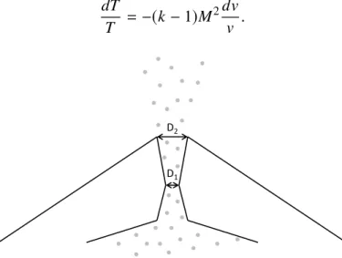
2.8.3 Supersonic gas jets with a shock . . . 40
Chapter overview
In this chapter the principal components of a laser wakefield accelerator are discussed and the underlying physical processes described. Main advantages and limitations of the technique are presented. Few target design concepts are introduced to counter these limitations.
2.1
Ponderomotive force
When a charged particle oscillates in a spatially or/and temporally inhomogeneous electromag-netic field, the total experienced force over a positive half-cycle is not exactly compensated after the sign reversal. Consequently, the particle may gain or lose net energy during the process (Boot & Harvie, 1957) (Meyerhofer, Knauer, McNaught, & Moore, 1996). This can be attributed to a term called the ponderomotive force. It is easily demonstrated in the non-relativistic case (Rax, 2005). Suppose a particle of mass m and charge q is located at position r = (x, y, z) in a transversely polarized electromagnetic field propagating in the z-direction and therefore described by
E(r, t) = E(r) cos(kz − ωt), B(r, t) = B(r) cos(kz − ωt),
where k is the absolute value of the wave vector, ω is the angular frequency, ant t is time. Here we assume the variation scale for respective electric and magnetic field amplitudes E(r) and B(r) to be much larger than the wavelength λ = 2π/k. The equation of motion for the test particle is thus d2r dt2 = q mE(r) cos φ(t) + q m dr dt × B(r) cos φ(t), (2.1)
where φ(t) = k z − ωt. In the non-relativistic regime, to a first approximation, the magnetic term can be ignored. One may therefore write
r(t)= r0+ rl(t)+ rnl(t),
where r0is the initial position of the test particle, rl(t) is the first-order perturbation which solves
d2rl dt2 =
q
mE(r) cos φ(t),
and rnl(t) is a higher-order correction term. The above equation can be easily integrated:
rl(t)= − q
2.1. Ponderomotive force 11
Figure 2.1 – Schematic overview of the ponderomotive force. A laser pulse with spherically symmetric Gaussian intensity distribution (normalized color scale) is propagating towards the right (black arrows). Three test electrons are encountered on the way, at some instant positioned at equal radial distances from the pulse center. They experience respective forces Fp1, Fp2 and Fp3, that are equal in magnitude, but pointing in different directions radially outwards (red arrows), pushing electrons 1 and 3 away from the optical axis.
The factor 1/ω2appears due to the integral of φ(t). We now go back to the full equation2.1 and expand the E-field term around r as a Taylor series:
m q
d2r
dt2 = (E(r) + rl∇E(r)) cos φ(t) + dr
dt × B(r) cos φ(t).
Using the expression for rl and considering again the fact that the terms with rnl are relatively small yields m q d2r nl dt2 = rl∇E(r) cos φ(t) + drl dt × B(r) cos φ(t) = −mωq 2E(r)∇E(r) cos 2φ(t) − q mωE(r) × B(r) cos2φ(t).
Finally, we average the cosine function over a full rapid cycle, and use the vector identity (E · ∇)E= 1
2∇E
2− E × (∇ × E), combined with Faraday’s law, to obtain ⟨ d2rnl dt2 ⟩ = − q2 4m2ω2 ∇E2.
Hence we conclude the "slow" force is proportional to the gradient of the electric field intensity, and the minus sign implies the particle is being pushed away from the strong-field zones towards the areas where the field is weak (Figure2.1). A further interesting point is that such behavior is independent of the wave polarization. This effect is defined as the ponderomotive
force. When particle interaction with intense laser fields is considered (I > 1018 W/cm2), the assumption that rl(t) and rnl(t) are small compared to r0is no longer valid, making the Taylor expansion inappropriate and the general relativistic treatment more complex (Quesnel & Mora, 1998). However, the final result is qualitatively the same – the force being proportional to the
Figure 2.2 – Schematic view of a wakefield structure. A laser pulse with spherically symmetric Gaussian intensity distribution (normalized color scale) is propagating towards the right, pushing the encountered electrons, here depicted as a collection of particles (black dots). This push causes density perturbations and excites plasma waves. Areas of strong Coulomb fields (red arrows) are thus created, that may accelerate appropriately placed test electrons to relativistic velocities. Note that off-axis these fields also have a radial component that can focus the beam. A more common way is to consider the electrons as a charged fluid, and this approach will be preferred later.
2.2
Qualitative description
The principle of laser wakefield acceleration usually relies on sending a single intense and ultrashort laser pulse into a gas target (Mangles et al., 2004) (Geddes et al., 2004) (Faure et al., 2004). The intensity achieved around the focal plane is orders of magnitude larger than the one required to ionize the gas, thus a volume of plasma is created in the proximity of the optical axis already before the main part of the pulse arrives. Hence it can often be assumed the laser is interacting directly with ionized matter. Since a light pulse has finitely extended spatio-temporal profile, plasma electrons are indeed exposed to an inhomogeneous electromagnetic field, and all the previous considerations regarding the ponderomotive force apply. While heavy ions effectively remain at their initial positions, the electrons get pushed away from the optical axis, leaving a net positive charge in this area. After the laser pulse passes by, this positive charge attracts the displaced electrons back, and a Langmuir oscillation is initiated (Tonks & Langmuir, 1929). A periodic structure of electronic density modulations then forms along the optical axis, and consequently it contains areas of Coulomb fields that may reach enormous amplitudes if driven by strong ponderomotive gradients (Figure2.2). This waveform follows the light pulse with a phase velocity vpequal to the laser group velocity vglas, which depends on the plasma density and is close to c. Such structure has also been observed directly in an experiment (Matlis et al., 2006) (Buck et al., 2011). If a co-propagating relativistic electron could be placed at an appropriate phase of this wave, it may "surf" the inner Coulomb field and gain additional energy. The "placement" of the electron can be external or occur automatically due to various reasons during the interaction between the plasma and the wakefield driver. Several known injection schemes with their advantages and disadvantages will be presented in section 2.4. In addition to high accelerating gradients, the wake structure posesses strong focusing forces, permitting improved output beam quality
2.3. Laser-driven wakefield generation formalism 13
in comparison to other laser-plasma interaction regimes. Even more, these focusing fields may cause accelerated particles to oscillate transversely to the direction of motion, creating a betatron X-ray source (Corde, Ta Phuoc, et al., 2013) that may turn out to be applicable in high-resolution imaging in medicine or industry. In the following the main concepts will be explored in greater detail.
2.3
Laser-driven wakefield generation formalism
2.3.1
1D plasma wave model
Good intuition about the behaviour of plasma waves and the transition between linear and nonlinear regimes can be obtained from a relatively simple one-dimensional model, as developed in (Dawson, 1959). Suppose a finite homogeneous collection of electrons gets perturbed in one dimension only. Let X(x0) be the displacement of an electron with equilibrium position x0, the motion being identical for all the particles in the given yz-plane. We assume the ordering of electrons is preserved, which is true if the change in X for a change ∆x0of the equilibrium position is larger than −∆x0. This condition can be formulated as
∂X
∂x0 > −1. (2.2)
The total electron coordinate is given by x = x0+ X(x0). While moving a distance X(x0) the electrons from the equilibrium plane x0pass by an amount of positive charge equal to en0X per unit area, where e is the elementary charge, and n0 is the unperturbed plasma density. Hence, if X is taken positive for the sake of the argument, we now have an excess positive charge en0X per unit area on the negative side of the electron sheath, and an excess negative charge −en0X per unit area on the positive side. From Gauss’ theorem one can write the E-field at the electron to be
E = 1 ϵ0en0X, yielding an equation of motion for the particle:
me d2X dt2 = −eE = − 1 ϵ0e2n0X, or d2X dt2 = −ω 2 pX,
where ϵ0is the vacuum permittivity, meis the electron mass, and ωp= √
e2n 0
meϵ0 is defined as
the plasma frequency. This is a usual equation of motion for a harmonic oscillator with the well-known general solution given by
X(x0)= X1(x0) sin ωpt+ X2(x0) cos ωpt.
Therefore, each electron undergoes harmonic oscillations about its equilibrium position independently of other particles. Let us consider now a particular solution of this equation described by
so that at t = 0 we have:
X = A sin kx0, E = 1
ϵ0en0A sin k x0,
x = x0+ X = x0+ A sin kx0.
This is of special interest considering the previously discussed concept of ponderomotive force, which has zero transverse component right on the optical axis (we could assign x0= 0 there, so that also the initial displacement Xt=0is zero), and grows larger further away from it, until one starts exiting the laser field. Let us plot now E /Emax as a function of x, the curve being described by the parametrisation:
{
x = x0+ A sin kx0, E
Emax = sin kx0,
where Emax = ϵ1
0en0A and x0is the parameter. We can immediately find that E /Emax will be
zero for
x= πl
k, l ∈ Z.
If we limit ourselves to one full sinusoidal cycle we find three zeros at x = −π/k, x = 0 and π/k. To further determine the shape of the curve we estimate the first derivatives with respect to x0: { d dx0x = 1 + Ak cos kx0, d dx0 E Emax = k cos kx0.
We see that in case A < 1/k the function x is strictly increasing, but it ceases to be so for A ≥ 1/k. One may also deduce that E/Emax has a maximum at
x = π 2k + A, and a minimum at x = − π 2k − A.
For A ≪ 1/k the additive amplitude term is negligible, and thus E /Emax(x) has a sinusoidal profile. As A grows, however, this shape is deformed with the extrema starting to move away from x = 0. When A = 1/k, the curve has vertical tangents at x = ±π/k, and for A > 1/k the function E /Emax(x) turns multivalued (Figure2.3). Clearly this is physically unfeasible, and in practice it means our condition2.2is no longer satisfied. This is considered as the point of
wave breaking, where the electron trajectories necessarily begin to cross, damping the plasma
wave. Assuming the particles oscillate with the wave number k = ωp/c, one may write at A= 1/k: E0= Emax|A=1/k = 1 ϵ0en0 c ωp = cmeωp e . (2.3)
This is defined as the cold nonrelativistic wave breaking field, limiting the amplitude of plasma wave that can be supported. Note that this edge is reached once the oscillation amplitude becomes comparable to the plasma wavelength.
2.3. Laser-driven wakefield generation formalism 15
Figure 2.3 – Parametric curves for E /E0(x0) against x(x0) for different values of the oscillation amplitude A.
2.3.2
Wakefields driven by weak Gaussian pulses
With the intuition gained in the previous section, one may now proceed to the 3D description of the laser wakefield generation process. In the case of weakly driven underdense plasmas, it is possible to find analytic expressions to relate the main parameters. We start with the Maxwell’s equations:
∇ · E= ρ
ϵ0, (Gauss’s law) (2.4)
∇ · B= 0, (Gauss’s law for magnetism) (2.5)
∇ × E= −∂B
∂t, (Faraday’s law) (2.6)
∇ × B= 1 c2
∂E
∂t + µ0J. (Ampère’s law revised by Maxwell) (2.7) Here ρ is the charge density, µ0 is the vacuum permeability, and J is the current density. To reduce the number of variables in the system we use the standard potential formulation (Griffiths, 2008):
B= ∇ × A, (2.8)
E= −∇Φ − ∂A
∂t . (2.9)
A and Φ are known as electrodynamic vector and scalar potentials, respectively. In addition,
we will need two fluid equations, namely the one for continuity: ∂n
∂t +∇ · (nv)= 0, (2.10)
and the equation of motion in electromagnetic fields: (∂
∂t +v · ∇ )
p= −e(E + v × B). (2.11)
In the above, n(r, t) is the plasma density, v(r, t) is its velocity, and p = γ(v)mev is the relativistic momentum. Evidently we are assuming the plasma to be a cold fluid. As a next step, we make a choice to work in Coulomb gauge, which implies ∇ · A = 0 (Griffiths, 2008). Combining this condition with equations2.4and2.9leads to the Poisson equation:
∇2Φ= e
ϵ0(n − n0)= e
where n0(r) is the equilibrium plasma density, and δn = n − n0 is the plasma density perturbation. We observe that the scalar Φ is dependent only on the plasma parameters, therefore all the information on the high-frequency laser field must be encoded in the vector potential A. This separability is a great advantage of using the Coulomb gauge in our description.
We may now plug the potential expressions2.8and2.9into Ampère’s law (eq. 2.7). After applying the vector identity ∇ × (∇ × A) = ∇(∇ · A) − ∇2A and the gauge condition ∇ · A = 0 one gets the wave equation for A:
( ∇2− 1 c2 ∂2 ∂t2 ) A= µ0env+ 1 c2 ∂ ∂t∇Φ. (2.13)
The same can be done for the equation of motion: (∂ ∂t +v · ∇ ) p= e ( ∇Φ+ ∂A ∂t − v × ∇ × A ) . (2.14)
To simplify the above, we need to demonstrate one mathematical property for the term (v · ∇)p. The following standard vector identity will be used again:
∇p 2
2 = (p · ∇)p + p × (∇ × p) = meγ((v · ∇)p + v × (∇ × p)). As a second step, from the definition
γ = (1 + p2 m2
ec2 )12
one can derive:
∇γ = 1 m2 ec2γ ∇p 2 2 . Combining these expressions yields the necessary property:
(v · ∇)p= mec2∇γ − v × (∇ × p). (2.15) Plugging it in the equation2.14gives:
∂
∂t(p − eA)= ∇(eΦ − mec2γ) + v × (∇ × (p − eA)).
Knowing that the curl of a gradient is always zero, the last trick is to take the curl of the above expression to obtain:
∂
∂t(∇ × (p − eA)) = ∇ × v × (∇ × (p − eA)).
The key observation now is that at time t = 0 the right hand side of the equation is zero, as before any perturbation occurs we have both p = 0 and A = 0, and thus ∇ × (p − eA) = 0. This implies that ∇ × (p − eA) = 0 at all times, and hence a reduced equation of motion can be concluded:
∂p
∂t =e∇Φ+ e ∂A
∂t − mec2∇γ. (2.16)
To tidy up the expressions, we introduce a set of normalized quantities: φ = eΦ/mec2,
a= eA/mec and u = p/mec, so that γ = (1 + u2)1/2. This allows us to write a fully general relativistic set of equations for our cold plasma:
2.3. Laser-driven wakefield generation formalism 17 ( ∇2− 1 c2 ∂2 ∂t2 ) a= k2 p 1 γ n n0u+ 1 c ∂ ∂t∇φ, (Wave equation) (2.17) ∂n
∂t +c∇ · (nu/γ) = 0, (Continuity equation) (2.18)
∇2φ = k2 p δn n0, (Poisson’s equation) (2.19) ∂u ∂t = c∇(φ − γ) + ∂a
∂t. (Fluid equation of motion) (2.20)
In the above kp= √
n0e2/mec2ϵ
0is the plasma wave number. In order to continue developing the 3D model, certain assumptions must now be made. To begin with, we require that the plasma be tenuous, so that ωp ≪ ω0, where ω0is the frequency of the driving field. This allows separating the fluid motion into two parts – a fast-varying one due to the high-frequency field, and the slow motion due to the evolving plasma perturbations, i. e. u = ufast+ uslow
(Mora & Antonsen, 1997). This permits separating the fluid equation of motion (2.20) into fast and slow parts:
ufast = a, (2.21)
and
∂uslow
∂t = c∇(φ − ⟨γ⟩), (2.22)
where ⟨...⟩ indicates averaging over a full period of high-frequency oscillations. We further assume a weakly relativistic case, which yields a ≪ 1, δn ≪ n0, u ≪ 1 and γ ≈ 1. The continuity equation taken to first order becomes
∂
∂tδn + cn0∇ · uslow = 0.
Taking the temporal derivative and combining it with equations2.19and2.22yields:
0 = ∂ 2 ∂t2 δn n0 + c∇ · ∂uslow ∂t = ∂t∂2 2 δn n0 + c 2∇2(φ − ⟨γ⟩) = (∂2 ∂t2 + ω 2 p ) δn n0 − c 2∇2⟨γ⟩ = (∂2 ∂t2 + ω 2 p ) δn n0 − c 2∇2⟨(1 + u2)12⟩.
One may now apply the binomial expansion:
(1 + u2)12 ≈ 1 + 1 2u 2= 1 + u 2 f ast 2 + u2 slow 2 + ufast· uslow.
We have seen that uf ast = a, hence the first term scales as a2. On the other hand, uslowterm originates due to the driver’s ponderomotive force, which has been shown to be proportional to the intensity, and I ∝ a2. Therefore, u2slow scales as a4, and ufast · uslow scales as a3, meaning
the last two expansion terms can be neglected in the weakly relativistic case. We conclude that (∂2 ∂t2 + ω 2 p ) δn n0 = c 2∇2⟨a 2⟩ 2 , (2.23) and similarly: (∂2 ∂t2 + ω 2 p ) φ = ω2 p ⟨a2⟩ 2 . (2.24)
A second important assumption is known as the quasistatic approximation. We first impose a coordinate system that is following the laser pulse, and thus the wake structure: t′ = t, ζ = z − ct. Since a tenuous plasma is considered, the group velocity of the laser pulse is indeed close to c. Then the derivatives are given by:
∂ ∂t = ∂ ∂t′− c ∂ ∂ζ, ∂2 ∂t2 = ∂2 ∂t′2 − 2c ∂2 ∂ζ ∂t′ + c2 ∂2 ∂ζ2, ∂ ∂z = ∂ ∂ζ, and the equation2.24can be expressed as:
( ∂2 ∂t′2 − 2c ∂2 ∂ζ ∂t′+ c2 ∂2 ∂ζ +ω2p ) φ = ω2 p ⟨a2⟩ 2 .
The quasistatic approximation supposes that in this new reference frame both the laser pulse and the plasma wave evolve slowly with time. This allows cancelling out all the terms that involve ∂/∂t′in the above to obtain:
( ∂2 ∂ζ2 + k 2 p ) φ = k2 p ⟨a2⟩ 2 . (2.25)
One can now solve this equation for a linearly polarized Gaussian driver pulse (Gorbunov & Kirsanov, 1987). It may be described by the normalized vector potential:
a= ˆa(r, ζ) cos(k0ζ)ex,
where the Gaussian envelope is given by ˆ a2(r, ζ) = a2 0exp(−ζ 2/L2 0) exp(−r 2/σ2).
Here k0 = 2π/λ0 is the laser wave number, with λ0 being the light wavelength, L0 = cτFWHM/(2√ln 2) is the driver pulse length with τFWHM the full width at half maximum (FWHM) pulse duration, r is the perpendicular distance from the optical axis, and σ determines the transverse beam size. The equation2.25takes the variable a2averaged over the high-frequency optical cycles, hence one gets an additional factor of 1/2 before deducing a similar expression with respect to the envelope ˆa:
( ∂2 ∂ζ2 + k 2 p ) φ = k2 p ˆ a2 4 . (2.26)
2.3. Laser-driven wakefield generation formalism 19
This can be solved by finding an appropriate Green’s function that satisfies ( ∂2 ∂ζ2 + k 2 p ) G(ζ, ζ′ )= δ(ζ − ζ′).
Here δ(ζ − ζ′) is the Dirac delta function. It can be shown that the general Green’s function for the above equation is given by
G(ζ, ζ′)= C 1exp(ikpζ) + C2exp(−ikpζ) + { 0, if ζ < ζ′, 1 kp sin kp(ζ − ζ ′), if ζ ≥ ζ′,
where C1and C2are arbitrary constants. We require a solution that drops to zero as ζ → +∞ (no plasma waves excited before the laser pulse arrives). This is then provided by
G(ζ, ζ′)= (Θ(ζ − ζ′
) − 1)sin kp(ζ − ζ ′) kp
.
In the above Θ(ζ − ζ′) is the Heaviside step function, which is equal to 1 for a positive argument, and 0 for a negative one. Finally, one may write down the solution to the equation 2.26: φ(ζ) =∫ +∞ −∞ G(ζ, ζ′ )k2 p ˆ a(ζ′) 4 dζ ′= −kp 4 ∫ +∞ ζ aˆ 2(ζ′) sin k p(ζ − ζ′)dζ′.
For potential far behind the laser pulse, or ζ < −L0, we may still integrate between −∞ and +∞: φ(ζ) = −kp 4 ( sin kpζ ∫ +∞ −∞ ˆ a2(ζ′) cos k pζ′dζ′+ cos kpζ ∫ +∞ −∞ ˆ a2(ζ′) sin k pζ′dζ′ ) . Note that ˆa2(ζ′) is an even function, thus its product with sin kpζ′is odd, and the second integral vanishes. What remains is then
φ(ζ) = −kp 4 a 2 0e −r2/σ2 sin kpζ ∫ +∞ −∞ e−ζ′2/L02cos kpζ′dζ′.
The last integral is in fact equivalent to a Fourier transfrom of a Gaussian function, and it may be looked up in many sources:
∫ +∞ −∞
e−ζ′2/L02cos kpζ′dζ′=
√
πL0e−k2pL20/4.
This determines the final expression for the normalized scalar potential:
φ(ζ) = −√πa2 0 kpL0 4 e−k2pL02/4e−r 2/σ2 sin kpζ. (2.27)
The slow-varying electric field may then be determined in cylindrical coordinates from
E= −∇Φ = −mec 2 e ∇φ = − mec2 e ( er δ δr +ez δ δz ) φ.
We conclude that for ζ < −L0the longitudinal and transverse electric fields can be respectively expressed by
Ez E0 = √ πa2 0 kpL0 4 e−k2pL02/4e−r2/σ2 cos kpζ, (2.28) Er E0 = − √ πa20 2 e −k2 pL02/4L0r σ2e −r2/σ2 sin kpζ, (2.29) where E0 = cmeωp
e is the already encountered nonrelativistic wave breaking field for cold plasmas. Few things can be deduced from here. Firstly, we see that both fields vary sinusoidally in ζ with the same period. However, they are offset by a phase of π/2. This means that only for one quarter of the period the wakefield will be both accelerating and focusing. In addition, the laser spot size plays an important role through dependence of the focusing field amplitude on ∝ e−r2/σ2/σ2. Finally, one can show that the maximum amplitude of the longitudinal field will be achieved when the parameters of plasma and laser pulse duration are set so that
kpL0= √
2.
In practical units, this resonance condition yields the following expression for choosing the plasma density: nr es(cm−3)= 1.7 × 10 21 τ2 FWHM(fs) , (2.30)
where τFWHM is the FWHM duration of the driver pulse, expressed in femtoseconds. In addition, from Poisson’s equation (2.19) one may calculate the density perturbation:
δn n0 = 1 k2 p ∇2φ = − 1 kpE0 ∇ · E= − 1 kpE0 ( 1 r ∂(rEr) ∂r + ∂Ez ∂ζ ) .
Separating the two corresponding contributions into δn = δnr+δnz, we obtain the longitudinal density perturbation: δnz n0 = √ πa2 0 kpL0 4 e −k2 pL20/4e−r2/σ2sin kpζ, (2.31)
and the radial term:
δnr n0 = δnz n0 4 σ2k2 p ( 1 − r 2 σ2 ) . (2.32)
We conclude that, as expected, the axial electric fields reach maximum values on optical axis (r = 0). Moreover, as the phase for δnz/n0as compared to Ez/E0, is also offset by π/2, the peak accelerating gradients in the direction of laser propagation (Ez < 0) are reached halfway between maxima and minima of the longitudinal density perturbation (Figure2.4).
2.3. Laser-driven wakefield generation formalism 21
Figure 2.4 – Curves depicting the on-axis solutions of normalized equations2.28(longitudinal electric field Ez/E0, dashed line) and2.31(longitudinal density perturbation δnz/n0, dotted line) behind a Gaussian laser pulse (solid line) travelling to the right with the resonance condition2.30satisfied. The regions with negative Ez/E0would accelerate a test electron in the direction of light propagation.
2.3.3
Strongly driven wakefields and the blowout regime
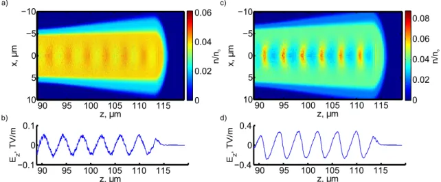
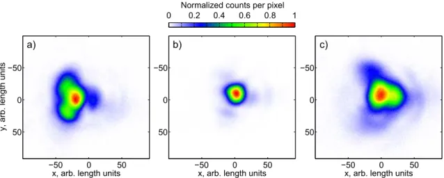
When the plasma is driven by a strong, relativistic laser pulse (a0 > 1), the previous model is no longer valid, and in fact analytic solutions for a 3D case have not been demonstrated. To study this interaction regime, numerical particle-in-cell (PIC) simulations are normally used (Dawson, 1983). The observed behavior, however, is highly reminiscent of the 1D plasma wave model described in section2.3.1. Figure 2.5shows an example of electron density maps and on-axis longitudinal electric field profiles obtained in weak and mildly relativistic driver cases using the PIC code Calder-Circ (Lifschitz et al., 2009). Here a resonant density plasma is driven by a 5 fs laser pulse with a normalized amplitude a0= 0.5 (plots a) and b)), and a0 = 1.2 (plots c) and d)). In the first case one may confirm that both
Figure 2.5 – PIC simulation results of a 5 fs laser pulse propagating in a resonant density plasma. a) Electron density map with a driver of sub-relativistic peak normalized amplitude (a0 = 0.5). b) On-axis longitudinal electric field (Ez) profile for the same case, showing a sinusoidal profile. c) Density map in the case of a mildly relativistic driver (a0 = 1.2). d) The corresponding on-axis longitudinal electric field, clearly following a deformed sinusoidal pattern and reaching much higher amplitudes. The outer regions coloured in blue correspond to non-ionized gas.
the density perturbation and the electric field profiles match the linear model predictions very well, as compared with Figure 2.4. However, the results obtained for a0 = 1.2 are quite different. The respective z-positions for maxima and minima of Ez are shifted, exactly as before in the 1D model (Figure 2.3), and the peak field values are significantly higher.
Figure 2.6 – Energetic electrons accelerated in a bubble-like struc-ture created by a strong laser pulse (Pukhov & Meyer-ter-Vehn, 2002).
Continuing the increase of driver amplitude a0towards strongly relativistic values would lead to further shifts of the extrema, to the point where the function Ez(z) becomes multi-valued, implying particle trajectory cross-ing and wave breakcross-ing. As will be discussed in section 2.4.2, this breaking can be used for injecting electrons in the wakefield. One may additionally notice in Figure 2.5c) that the plasma perturbations have become really large, with certain areas close to the optical axis coming near zero density levels, i. e. δn ≃ n0. This implies approaching a regime first described in (Pukhov & Meyer-ter-Vehn, 2002), where the space behind the laser pulse becomes essentially void of electrons (Figure2.6). It is now commonly known as the bubble, or blowout regime, and is often preferred during experiments both due to its high accelerating gradients and extended regions having focusing properties (i. e. the wakefield is both accel-erating and focusing for > 1/4 of the plasma wave period). In addition, it is possible to obtain beams with narrow enery spreads (Mangles et al., 2004) (Geddes et al., 2004) (Faure et al., 2004) (Tsung et al., 2006), which is often a desired property. In order to access the bubble regime, several conditions should be matched (Lu et al., 2007). Firstly, the pulse needs to be intense enough to expel all electrons away from the optical axis. Simulations indicate that normalized laser amplitudes a0& 2 are necessary, equivalent to peak intensities I & 1019W/cm−2. Additionally, the driving pulse should fulfil the bubble resonance condition:
cτFWHM ≈ σ ≈ λp/2, (2.33)
where the plasma wavelength λpis obtained accounting for a relativistic correction factor: λp=
√ a02π
kp
, (2.34)
and all the other terms are as defined before. With these requirements satisfied, it is possible to determine the total expected energy gain in this regime, limited by dephasing (see later section2.5.3): ∆E[GeV] ≃ 1.7( P[TW] 100 )1/3( 1018 n[cm−3] )2/3( 0.8 λ0[µm] )4/3 . (2.35)
We conclude that for an appropriate titanium-sapphire 100 TW laser system one should be able to obtain GeV-scale electrons. This has also been proved experimentally (Leemans et al., 2006).
2.4. Accelerator injection schemes 23
2.4
Accelerator injection schemes
After describing the formation of plasma waves, it is necessary to discuss the second crucial component of a wakefield accelerator – the particle injection mechanism. In order to experience net energy gain, a test electron has to get trapped, which requires satisfying certain initial conditions that concern its velocity and position within the plasma wave (i. e. the wave phase). As the wakefield is propagating nearly at the speed of light, the particle also needs to reach relativistic velocity within a single accelerating half-period of the plasma wave – otherwise the wave would outrun the particle, placing it in the decelerating region and ultimately leading to approximately zero total energy gain. An initially stationary electron could also be injected, provided the wakefield is sufficiently strong, and the particle is placed at an optimal phase. Multiple wakefield injection schemes have been described in literature by now.
2.4.1
External injection
The conceptually simplest technique is using an external particle injector. However, this idea runs into many difficulties. To begin with, we note that typical plasma wavelengths in LWFA are on the order of few tens of, or even few microns only. Hence the witness electron bunch duration should be significantly below 100 fs in order for all of its slices to experience a similar net effect. This is a big challenge even today, and was unachievable back in the period when such injection method was first attempted. Secondly, the particle beam needs to be focused to a spot size significantly smaller than the laser spot size, or otherwise again the fields experienced by different parts of the bunch would not be the same. Finally, for reproducibility of results the wakefield driver and the particle bunch need to be synchronized at the femtosecond level, which, depending on the exact method to pre-accelerate particles, might be another great challenge due to electronic jitter issues. All points considered, it is not surprising that this concept, although succesfully verified (Everett et al., 1994) (Amiranoff et al., 1998), hardly produced beams of satisfactory quality and has not been overly popular. Notable exceptions are the more exotic cases of ultrahigh-energy particle-driven accelerators, where the used plasma wavelengths are larger by orders of magnitude (Litos et al., 2014) (Gschwendtner et al., 2016) (Adli et al., 2018) (Doche et al., 2017).
2.4.2
Self-injection by wave breaking
It has been discussed in the section2.3how strong driving of plasma waves mathematically leads to the longitudinal electric field function Ez(z) turning multi-valued for the considered model. Physically such a situation is clearly unfeasible and in practice it implies a violation of the assumption that there are no plasma electron trajectory crossings (equation2.2). This is known as the wave breaking, which limits the wake amplitude and may sometimes lead the surplus electrons (i. e. the ones that are no longer part of the wake structure) to occur in regions where the conditions are favorable for trapping in the plasma wave (Katsouleas & Mori, 1988), (Bulanov, Pegoraro, Pukhov, & Sakharov, 1997), (Bulanov, Naumova, Pegoraro, & Sakai, 1998), (Kostyukov, Nerush, Pukhov, & Seredov, 2009). As predicted by theory, self-injection has been demonstrated to be a threshold effect (Mangles et al., 2012), and higher plasma densities are required for running with lower power lasers, increasing the influence of various nonlinear light-matter interaction phenomena and leading to below-average source stability. In addition, multiple self-injection regimes have been shown to exist, having slightly different properties (Corde, Thaury, et al., 2013). Finally, since both the wakefield generation and particle injection are due to a single driver pulse, this method does not provide many
tuning knobs to control the electron beam parameters. Despite these drawbacks, self-injection has been frequently preferred in experiments, mainly because of its simplicity.
2.4.3
Colliding-pulse injection
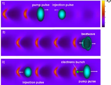
To counter the drawbacks mentioned in the previous section and at least partially decouple the wakefield generation and injection mechanisms, using an additional laser pulse has been proposed. The initial idea was to give an additional kick to a collection of electrons in a confined area by the ponderomotive force of a perpendiculary propagating injector pulse (Umstadter, Kim, & Dodd, 1996). Later it has been suggested that a beat wave generated by the interference between two counterpropagating laser beams could do this job even better due to sharper ponderomotive gradients as well as symmetry reasons (Esarey, Hubbard, Leemans, Ting, & Sprangle, 1997) (Fubiani, Esarey, Schroeder, & Leemans, 2004) (Figure2.7). This technique has been experimentally confirmed to not only produce electrons with a narrow energy spread thanks to well-defined position of injection, but also allow energy tunability by adjusting the collision point within the plasma channel through an optical delay line (Faure et al., 2006). On the other hand, the need to overlap two laser beams both spatially and temporally implies such a system is significantly more difficult to align.
Figure 2.7 – Illustration of the colliding-pulse injection technique. An intense pump pulse drives a plasma wakefield. At some point it encounters a counter-propagating injection pulse, and a beat wave is created in the overlap region. This beat wave may trigger an injection of an electron bunch in the plasma wave. Taken from (Faure, 2014).
2.4.4
Ionization-induced injection
One of the two well-known controlled injection schemes that require only one laser pulse relies on the fact that gases with higher atomic numbers have electrons with several very different ionization potential levels. For example, the first five outer-shell (L-shell) electrons of nitrogen require below 100 eV of energy to dissociate from the parent molecule. Using the barrier-suppression ionization model (Delone & Krainov, 1998), the required light intensity may be calculated via
I [W/cm2]= 4 × 10⁹E 4 i[eV]
2.4. Accelerator injection schemes 25
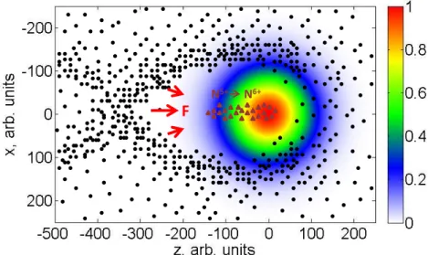
to be below 1.5 × 10¹⁶W/cm2. Here Ei is the corresponding ionization potential level and Z is the resultant charge of the ion after the ionization event given in atomic units. This value is orders of magnitude below the peak intensities at which LWFA is normally operated, and hence the leading edge of the laser pulse is sufficient to completely strap away the considered particles from the nitrogen parent molecules. However, the ionization of the first K-shell electron that is close to the nucleus requires an energy of 552 eV to dissociate, corresponding to I ≈ 1 × 10¹⁹ W/cm2. Such intensities are usually reached only at the center of the laser pulse, hence the N5+ → N6+ electrons are born already inside the first wakefield period (Figure2.8). If the plasma wave is strong enough, these particles may then be captured and accelerated to relativistic velocities. This technique is experimentally fairly simple, and has been widely used since its first demonstrations (Pak et al., 2010) (McGuffey et al., 2010). However, by default it does not offer many beam control tools, and in order to avoid broad electron energy distributions more advanced target design is required (Pollock et al., 2011) (Vargas et al., 2014).
Figure 2.8 – Illustration of the ionization injection principle. The front of a wakefield-driving intense laser pulse completely ionizes the L-shell of nitrogen gas (black dots). At the center of the pulse, where the light field is the strongest, some K-shell electrons may also be ionized (brown triangles). However, they do not experience the same ponderomotive force and thus do not follow the same trajectories as the particles born at the front. They remain close to the optical axis, and, if the wakefield is strong enough, may be trapped. N2is most commonly used for the technique, but other gases are possible, as well.
2.4.5
Density-downramp injection
Another well-known injection mechanism is based on deliberate variations of the plasma density profile encountered by the driver pulse. As discussed before, electrons may be trapped by the wakefield as long as the latter does not outrun them, placing the particles in its decelerating phase, where no energy gain could be reached. Two parameters are of importance here – the amplitude of the wakefield, affecting how quickly the particles may get accelerated to the wake phase velocity vp/ c, and the phase velocity itself. If it could be lowered, then initially slower electrons would also be able to catch up with the wave. For a varying density profile the plasma equation under quasistatic approximation (2.25) reads:
( ∂2 ∂ζ2 + k 2 p(z) ) φ = k2 p(z) ⟨a2⟩ 2 . (2.37)
Following the same procedure as before, one may show that the solution behind the laser pulse has the form:
φ(ζ, z) = φ0(z) sin kp(z)ζ, (2.38) where φ0(z) = − √ πa2 0kp(z)L0exp(−kp(z) 2L2 0/4) exp(−r
2/σ2)/4 is the wakefield amplitude (compare eq. 2.27), and ψ = kp(z)ζ = kp(z)(z − ct) is its phase. Bear in mind we are still assuming tenuous plasmas, so that one may continue to claim that the group velocity vg(z, t) ≈ c (otherwise one would need to use ζ = z − vg(z)t, making the change of variables (z, t) → (ζ, t) more complicated). It is then straightforward to obtain the local wave frequency and wave number:
ω(ζ, z) = −∂ψ/∂t = kp(z)c= ωp(z), k(ζ, z) = ∂ψ/∂z = kp(z)+ ζ∂kp/∂z. This may be used to obtain the local phase velocity:
vp(ζ, z) = ω(ζ, z) k(ζ, z) = c 1 + k1pζ∂k∂zp . (2.39)
For a downward density gradient one has ∂ kp/∂z < 0. Behind the laser pulse we also have ζ < 0. Hence, for a decreased wave number kp one also obtains a decrease in the phase velocity, which eases the electron trapping. First suggested and demonstrated for mild transitions (Bulanov et al., 1998) (Geddes et al., 2008), the method applied to sharp density drops created by obstacles placed in supersonic gas flow or by hydrodynamic expansion of pre-ionized gas allowed obtaining beams with a few-percent energy spread, some tunability and good reproducibility (Suk, Barov, Rosenzweig, & Esarey, 2001) (Faure, Rechatin, Lundh, Ammoura, & Malka, 2010) (Gonsalves et al., 2011) (Buck et al., 2013).
2.4.6
Other injection types due to wakefield slow-down
In the previous section we have discussed how the back of the wakefield could be deliberately slowed down by plasma density tailoring. This, however, is not the only reason the wake phase velocity vpcould face a reduction, aiding particle injection. The evolution of the driving laser pulse while it propagates in the plasma may also produce similar effects. Experimentally such processes are difficult to distinguish from simple self-injection due to wave breaking, but numerical studies have provided a lot of interesting evidence for their occurence possibilities. One such case has been discussed in (Beaurepaire, Lifschitz, & Faure, 2014) for ultrashort broad-bandwidth drivers, which experience rapid self-phase modulation in high-density plasma, symmetrically redshifting the front and blueshifting the back of the Gaussian light packet (Watts et al., 2002). This occurs simultaneously with strong dispersion effects that lead to the red wavelengths slipping behind the blue ones (i. e. building up a negative chirp), the final result being an overall redshift of the entire spectrum. Such modification significantly reduces the laser group velocity vg, which in turn results in the wakefield slow-down, relaxing the requirements for electron trapping. It has been also suggested that the first wake period
2.5. LWFA limiting factors 27
may undergo an expansion due to laser diffraction (Kalmykov, Yi, Khudik, & Shvets, 2009) or the expansion may be forced by the ponderomotive force of a counter-propagating injection pulse (Lehe, Lifschitz, Davoine, Thaury, & Malka, 2013). In both cases the wake phase velocity is reduced, enhancing the particle trapping.
2.4.7
Combined injection methods
The schemes that have been discussed above essentially form a complete set of currently known LWFA injection methods. Several original approaches, however, that combine more than one described technique in an experiment, have also been suggested. A fusion of ionization-induced and density transition injection schemes has been demonstated to yield a reliable source with tunable energy (Thaury et al., 2015). Potentially even higher quality beams could be obtained by colliding two laser pulses to cause K-shell ionization only in the region of their overlap (Wan et al., 2016), however in practice this approach might be hard to set up. An even more ambitious scheme utilizes two transverse laser beams that collide exactly on the optical axis at a carefully defined distance behind the driver pulse to give an initial kick to nearby electrons via induced ponderomotive force (Chen et al., 2014) or once again to ionize the K-shell of high-Z gas in a tightly localized region (Li et al., 2013). So far these methods remain theoretical, but it would be very interesting to see what technical solutions may later be used to implement this practically and what would be the parameters of such electron source.
2.5
LWFA limiting factors
Naturally the acceleration process will stop at a certain point. In this section we discuss what are the main limiting factors of LWFA.
2.5.1
Diffraction
It is well known that a light beam may not stay focused for an arbitrarily long distance due to diffraction effects. A typical Gaussian laser beam intensity evolution is defined by the focusing geometry. If we focus the beam at an angle θ ≈ tan θ = w(z)/z with respect to the optical axis, the achievable spot size (i. e. beam waist) in vacuum is given by:
w0 ≈ λ0
πθ, (2.40)
where λ0is the laser wavelength. It is common to define the Rayleigh length as the distance from the focal plane where the beam intensity drops by a factor of two (Figure2.9). It is related to the spot size via
zR = πw2
0
λ0 . (2.41)
The beam radius at a distance z from the focal plane is given by
w(z)= w0 √ 1 + ( z zR )2 . (2.42)
Evidently in the absence of guiding the laser pulse will not be able to maintain the high relativistic intensities required for wakefield generation over a distance significantly longer
than zR. On the other hand, as seen from equation2.41, increasing zRmeans also increasing the focal spot size, leading to lower peak intensity. Therefore the focusing geometry needs to be chosen carefully for an experiment. On the other hand, in case of a very strong driver, diffraction may to a great extent be outcompeted by relativistic self-focusing, which will be discussed in a later section.
Figure 2.9 – Gaussian beam waist w(z) as a function of the on-axis distance from the focal plane z (w(z = 0) = w0) for a given Rayleigh length zR.
2.5.2
Laser depletion
As the laser pulse continuously excites the wakefield, naturally it is losing its own energy. After some distance of propagation inside the plasma it will no longer be intense enough to generate waves. This distance is known as the pulse depletion length Lpd, and may be estimated using energy conservation. For tenuous plasmas in the weakly driven case, one may write EL2L0= Ez2Lpd, where EL and Ez are the laser and the longitudinal plasma wave field amplitudes, respectively, and L0is the driver pulse length (Esarey, Sprangle, Krall, & Ting, 1996). Since EL = mcω0a0/e, assuming the resonance condition kpL0=
√
2 is satisfied and using equation2.28, one gets
Lpd = E2 L E2 z L0 = ω 2 0 ω2 p 8 πa2 0 eL0≈ ω 2 0 ω2 p cτFWHM a2 0 . (2.43)
In the nonlinear regime (a0 ≫ 1), it is given by (Bulanov, Inovenkov, Kirsanov, Naumova, & Sakharov, 1992) (Lu et al., 2007)
Lpd = ω2 0 ω2 p cτFWHM. (2.44)
2.5.3
Dephasing
Once electrons are injected into the wakefield, their velocities very rapidly approach the speed of light c. At some point the bunch may become faster than the plasma wave itself, propagating at vp = vglas, where vglas . c is the laser pulse group velocity. This way it enters the decelerating wakefield region and the energy gain stops. This is characterised by the dephasing
length Ldeph, which may be estimated from the phase relation kpζ = kp(Ldeph− vptdeph)= π, where tdephis the dephasing time. Assuming the electrons are moving at a constant speed of light, one gets Ldeph = ctdeph, and consequently kp(ctdeph− vptdeph)= π. Hence follows that Ldeph = λp/(2(1 − βp)), where βp= vp/c. In the case γp ≫ 1, this simplifies to
Ldeph≈ γ2pλp. (2.45)
This equation can be further rearranged using the electromagnetic wave dispersion relation in a plasma:
ω2 0= ω
2