Design and development of intelligent actuator control
methodologies for morphing wing in wind tunnel
by
Shehryar KHAN
MANUSCRIPT BASED THESIS PRESENTED TO ÉCOLE DE
TECHNOLOGIE SUPÉRIEURE IN PARTIAL FULFILLMENT FOR THE
REQUIREMENTS OF THE DEGREE OF DOCTOR OF PHILOSOPHY
Ph.D.
MONTREAL, 2020-01-06
ÉCOLE DE TECHNOLOGIE SUPÉRIEURE
UNIVERSITÉ DU QUÉBEC
© Copyright reserved
It is forbidden to reproduce, save or share the content of this document either in whole or in parts. The reader who wishes to print or save this document on any media must first get the permission of the author.
BOARD OF EXAMINERS
THIS THESIS HAS BEEN EVALUATED BY THE FOLLOWING BOARD OF EXAMINERS
Professor Ruxandra Botez, Thesis Supervisor
Department of Automated Manufacturing Engineering at École de technologie supérieure
Professor Vincent Demers, President of the Board of Examiners
Department of Mechanical Engineering at École de technologie supérieure
Professor Vincent Duchaine, Member of the jury
Department of Automated Manufacturing Engineering at École de technologie supérieure
Professor Ramin Sedaghati, External Evaluator
Department of Mechanical and Industrial Engineering at Concordia University
THIS THESIS WAS PRENSENTED AND DEFENDED
IN THE PRESENCE OF A BOARD OF EXAMINERS AND PUBLIC ON 3RD DECEMBER 2019
ACKNOWLEDGMENT
I would like to dedicate this work to my mother; without her sacrifices, I would not have been able to achieve too much in life, and to my father, who served in the aviation industry and at the United Nations and he had to stay far from home, to make sure we could receive the best education.
I offer my sincere gratitude to my research director Professor Ruxandra Botez for recognizing my potential, and for giving me an opportunity to pursue research and development under her leadership, and for giving me an opportunity to continue research in the prestigious international project CRIAQ MDO 505. I also wish to thank her for her supervision to help me to complete my exchange studies at McGill University, and also to complete the course work requirements for my PhD. I want also to thank Dr. Teodor Lucian Gregory for many useful discussions and for his leadership in various aspects of research. I would also like to thank Mr. Oscar Carranza for his cordial collaboration in the LARCASE, his discussions and his supervision in ensuring the sensitive equipment to be handled in a safe and appropriate manner. I would like to thank my colleague Tchatchueng Kammegne for many useful duscussions on various research aspects, that led to useful results. I would also like to express my gratitude to Mohammed Sadok Guezguez for his non-stop efforts during the project, and for his support in the validation of the controller during bench testing, and finally at the wind tunnel at the IAR-NRC Ottawa. I would also like to thank Miss Andrea Koreanschi and Mr.Oliviu Sugar Gabor for their useful discussions and brainstorming on the aerodynamic aspects of the project, and also would like to thank very much Manuel Flores, for the useful discussions during the evolution of the project. I would like to acknowledge the expertise of George Ghazi for our numerous productive discussions during various debugging sessions, and also to thank very much Yvan Tondji for his collaboration in the post-processing of the wind tunnel data.
I would like to express my sincere appreciation to the CRIAQ MDO 505 project’s academic partners from the University of Naples Mr.Rosario Pecora, Mr.Leonardo Lecce and Professor Eric Laurendeau from Ecole Polytechnique, and to industrial partners Mr. Phillippe Molaret
VI
and Mr.Louis Xavier from Thales Canada, and Patrick Germain and Mr. Fassi Kafyeke from Bombardier Aerospace.
Special thanks are due to Mr. Mahmoud Mamou and Mr. Youssef Mebarki for the supervision of the wind tunnel testing at the IAR-NRC. Without the contributions of committed experts and students it would not have been possible to realize the CRIAQ MDO 505 project. This project has helped me to develop many technical and leadership skills from countless interactions with academic and industrial partners.
Finally, I would like to thank my wife for being with me throughout all these challenging times. I would also like to thank my sons Muhammad Musa and Haroon for being an inspiration to pursue excellence in my career. I would also like to acknowledge the support of my friends whom presence during all this time helped me to finalize this PhD thesis.
Conception et développement de méthodes de commande intelligente d'actionneurs pour la déformation d'ailes en soufflerie
Shehryar KHAN
RESUME
Afin de protéger notre environnement en réduisant les émissions de carbone de l'aviation et en rendant les opérations aériennes plus économiques en carburant, plusieurs collaborations ont été établies à l'échelle internationale entre les universités et les industries aéronautiques du monde entier. Suite aux efforts de recherche et développement du projet CRIAQ 7.1, le projet MDO 505 a été lancé dans le but de maximiser le potentiel des avions électriques. Dans le projet MDO 505, de nouveaux actionneurs basés sur des moteurs à courant continu sans balai sont utilisés. Ces actionneurs sont placés le long de la corde sur deux lignes d'actionnement. L'aile de démonstration, composée de longerons et d'un revêtement souple, est composée de fibres de verre. Les modèles 2D et 3D de l'aile ont été développés en XFOIL et Fluent. Ces modèles d'ailes peuvent être programmés pour déformer l'aile dans diverses conditions de vol tel que le nombre de Mach, l’angle d'attaque et le nombre de Reynolds, permettant ainsi de calculer des profils optimisés. L'aile a été testée dans la soufflerie de l'IRA NRC (Ottawa).
Les actionneurs sont montés avec des capteurs LVDT pour mesurer le déplacement linéaire. Le revêtement flexible est intégré aux capteurs de pression pour détecter l'emplacement du point de transition laminaire - turbulent. Cette thèse présente à la fois la modélisation linéaire et non linéaire du nouvel actionneur de déformation. Les techniques classiques et modernes de l'IA pour la conception du système de commande d'actionneur sont présentées.
La conception et la validation de la commande de l'actionneur l’aide de la soufflerie renvoient à trois articles, le premier article présente la conception du contrôleur et les tests ensoufflerie du nouvel actionneur de déformation pour l’extrémité d'une aile d'avion. Les nouveaux actionneurs de déformation sont constitués d’un moteur BLDC couplé à un engrenage qui convertit le mouvement de rotation en mouvement linéaire. La modélisation mathématique est
VIII
effectuée afin de dériver une fonction de transfert basée sur les équations différentielles. Afin de pouvoir déformer l’aile, il a été conclu qu'un contrôle de la position, de la vitesse et du courant de l'actionneur devait être effectué. Chaque contrôleur est conçu en utilisant la méthode de contrôle de modèle interne (IMC) à partir de la théorie de contrôle classique sur le modèle linéaire de l’actionneur. Les gains obtenus ont été testés avec succès sur le modèle non linéaire de l'actionneur à partir de simulations. Enfin, l’essai de l’actionneur sur un banc de test est suivi d’un essai en soufflerie. Les données de la thermographie infrarouge et des capteurs de Kulite ont révélées qu'en moyenne, dans tous les cas de vols étudiés, le point de transition laminaire à turbulent était retardé au bord de fuite de l'aile.
Le deuxième article porte sur l’application de l’optimisation de l’essaim de particules pour la conception du contrôle de l’actionneur du nouvel actionneur de déformation. Récemment, l'algorithme d'optimisation d'essaims de particules a acquis une réputation dans la famille des algorithmes évolutifs pour la résolution de problèmes non convexes. Bien qu'il ne garantisse pas la convergence, toutefois, s’il est exécuté plusieurs fois en variant les conditions initiales, il permet alors d'obtenir les résultats souhaités.
Dans l'optimisation des essaims de particules, toutes les particules sont associées au vecteur de position et de vitesse. À chaque itération, la vitesse de la particule est calculée sur la base de la meilleure particule et de la meilleure particule globale en association avec des paramètres cognitifs et sociaux ainsi que du moment d'inertie de la particule. Une fois la vitesse calculée, la position suivante de la particule est calculée à l'aide de la somme de la position actuelle de la particule et de la vitesse. Bien que l'optimisation des essaims de particules ne garanti pas de converger vers un minimum global, son algorithme moins coûteux en terme de calcul repose néanmoins sur un nombre réduit d'opérations pour explorer l'espace de recherche. Suite au calcul réussi de la conception du contrôleur utilisant l'optimisation de l'essaim de particules, ses essais sur un banc de test ont été réalisés avec succès. Enfin, les essais en soufflerie ont été effectués sur la base du contrôleur conçu. Les résultats des capteurs infrarouge et Kulite ont révélé une extension des écoulements laminaires sur l’aile en train de se déformer.
IX
Le troisième et dernier article présente la conception du contrôleur par logique floue. Le moteur BLDC est couplé au réducteur qui convertit le mouvement rotatif en mouvement linéaire, ce phénomène est utilisé pour pousser et tirer le revetement flexible qui se déforme. Le moteur BLDC lui-même et son interaction avec l'engrenage et le revetement déformant sont exposés aux charges aérodynamiques, ce qui en fait un système non linéaire complexe. Il a donc été décidé de concevoir un contrôleur flou capable de contrôler l'actionneur de manière appropriée. Trois contrôleurs flous ont été conçus pour le contrôle du courant, de la vitesse et de la position de l'actionneur de déformation. Les résultats de la simulation ont révélé que le contrôleur devellopé peut contrôler l'actionneur avec succès. Enfin, le contrôleur conçu a été testé en soufflerie et les capteurs infrarouge et Kulite ont révélé une amélioration de la position du point de transition de l'aile déformée.
Design and development of intelligent actuator control methodologies for a morphing wing in a wind tunnel
Shehryar KHAN
ABSTRACT
In order to protect our environment by reducing the aviation carbon emissions and making the airline operations more fuel efficient, internationally, various collaborations were established between the academia and aeronautical industries around the world. Following the successful research and development efforts of the CRIAQ 7.1 project, the CRIAQ MDO 505 project was launched with a goal of maximizing the potential of electric aircraft. In the MDO 505, novel morphing wing actuators based on brushless DC motors are used. These actuators are placed chord-wise on two actuation lines. The demonstrator wing, included ribs, spars and a flexible skin, that is composed of glass fiber. The 2D and 3D models of the wing were developed in XFOIL and Fluent. These wing models can be programmed to morph the wing at various flight conditions composed of various Mach numbers, angles of attack and Reynolds number by allowing the computation of various optimized airfoils. The wing was tested in the wind tunnel at the IAR NRC Ottawa.
In this thesis actuators are mounted with LVDT sensors to measure the linear displacement. The flexible skin is embedded with the pressure sensors to sense the location of the laminar-to-turbulent transition point. This thesis presents both linear and nonlinear modelling of the novel morphing actuator. Both classical and modern Artificial Intelligence (AI) techniques for the design of the actuator control system are presented. Actuator control design and validation in the wind tunnel is presented through three journal articles; The first article presents the controller design and wind tunnel testing of the novel morphing actuator for the wing tip of a real aircraft wing. The new morphing actuators are made up of BLDC motors coupled with a gear system, which converts the rotational motion into linear motion. Mathematical modelling is carried out in order to obtain a transfer function based on differential equations. In order to control the morphing wing it was concluded that a combined position, speed and current
XII
control of the actuator needs to be designed. This controller is designed using the Internal Model Control (IMC) method for the linear model of the actuator. Finally, the bench testing of the actuator is carried out and is further followed by its wind testing. The infra red thermography and kulite sensors data revealed that on average on all flight cases, the laminar to turbulent transition point was delayed close to the trailing edge of the wing.
The second journal article presents the application of Particle Swarm Optimization (PSO) to the control design of the novel morphing actuator. Recently PSO algorithm has gained reputation in the family of evolutionary algorithms in solving non-convex problems. Although it does not guarantee convergence, however, by running it several times and by varying the initialization conditions the desired results were obtained. Following the successful computation of controller design, the PSO was validated using successful bench testing. Finally, the wind tunnel testing was performed based on the designed controller, and the Infra red testing and kulite sensor measurments results revealed the expected extension of laminar flows over the morphing wing.
The third and final article presents the design of fuzzy logic controller. The BLDC motor is coupled with the gear which converts the rotary motion into linear motion, this phenomenon is used to push and pull the flexible morphing skin. The BLDC motor itself and its interaction with the gear and morphing skin, which is exposed to the aerodynamic loads, makes it a complex nonlinear system. It was therefore decided to design a fuzzy controller, which can control the actuator in an appropriate way. Three fuzzy controllers were designed each of these controllers was designed for current, speed and position control of the morphing actuator. Simulation results revealed that the designed controller can successfully control the actuator. Finally, the designed controller was tested in the wind tunnel; the results obtained through the wind tunnel test were compared, and further validated with the infra red and kulite sensors measurments which revealed improvement in the delay of transition point location over the morphed wing.
TABLE OF CONTENTS
CHAPTER 1 INTRODUCTION ... 1
1.1 MOTIVATION AND PREVIOUS WORK AT THE LARCASE ... 1
1.2 MORPHING WING CLASSIFICATION ... 6
1.3 TYPES OF ACTUATORS AND CONTROL TECHNIQUES... 7
CHAPTER 2 RESEARCH APPROACH AND OBJECTIVES ... 21
2.1 BACKGROUND OF THE CRIAQMDO505PROJECT ... 21
2.2 MORPHING WING PRESENTATION ... 23
2.3 FEATURES OF THE IAR-NRC WIND TUNNEL TESTING FACILITY IN OTTAWA ... 26
2.4 RESEARCH OBJECTIVES ... 26
2.5 RESEARCH APPROACH AND THESIS ORGANIZATION ... 26
2.6 CONTRIBUTIONS ... 32 2.7 SUMMARY OF CHAPTER 1 ... 35 2.8 SUMMARY OF CHAPTER 2 ... 35 2.9 SUMMARY OF CHAPTER 3 ... 35 2.10 SUMMARY OF CHAPTER 4 ... 37 2.11 SUMMARY OF CHAPTER 5 ... 39
CHAPTER 3 FIRST ARTICLE... 41
3.1 INTRODUCTION ... 42
3.2 RESEARCH PROJECT BACKGROUND ... 45
3.3. MATHEMATICAL AND SOFTWARE MODELLING OF ACTUATOR ... 48
3.4. TUNING CONTROL LOOPS USING IMC TECHNIQUE ... 54
3.5. BENCH TESTING OF MORPHING WING CONTROL SYSTEM ... 60
3.6. EVALUATION OF MORPHING WING EXPERIMENTAL MODEL THROUGH WIND TUNNEL TESTING ... 65
3.7. CONCLUSIONS ... 71
XIV
CHAPTER 4 SECOND ARTICLE ... 77
4.1. ABSTRACT ... 78
4.2. INTRODUCTION ... 79
4.3 ARCHITECTURE OF THE MORPHING WING EXPERIMENTAL MODEL ... 84
4.4.CONTROL SYSTEM TUNING PROCEDURE BASED ON PARTICLE SWARM OPTIMIZATION (PSO) METHOD ... 86
4.5. PARTICLE SWARM OPTIMIZATION ALGORITHM ... 88
4.6.CONTROL SYSTEM TUNING ... 91
4.7. EXPERIMENTAL INSTRUMENTATION OF THE MORPHING WING MODEL AND WIND TUNNEL TESTING ... 95
4.8. CONCLUSIONS ... 101
4.9 ACKNOWLEDGMENTS ... 102
CHAPTER 5 THIRD ARTICLE ... 103
5.1. INTRODUCTION ... 104
5.2. SHORT DESCRIPTION OF THE MORPHING WING PROJECT ... 107
5.3. PHYSICAL ARCHITECTURE AND SIMULINK MODEL OF THE CONTROLLED ACTUATOR ... 111
5.4 THE CONTROL SYSTEM DESIGN AND NUMERICAL VALIDATION RESULTS ... 114
5.5. WIND TUNNEL EXPERIMENTAL TESTING OF THE WING-AILERON MORPHING SYSTEM ... 123
5.6. CONCLUSIONS ... 132
5.6 ACKNOWLEDGMENTS: ... 133
OVERALLCONCLUSIONANDRECOMMENDATION ... 134
APPENDIX A ... 137 APPENDIX B ... 138 APPENDIX C ... 140 APPENDIX D ... 142 APPENDIX E ... 143 APPENDIX F ... 145 APPENDIX G ... 147 LIST OF REFERENCES ... 149
XV
LIST OF TABLES
Table 2.1 Data sheet of the BLDC motor integrated in the morphing actuator ...28
Table 4.1 Parametric study of PSO for morphing wing actuator control ...93
Table 5.1 Parameters of the mf for the “PositionFIS” first input and for the
“CurrentFIS” both inputs. ...118
Table 5.2 Parameters of the mf for the both inputs of the “SpeedFIS”. ...119
LIST OF FIGURES
Figure 1.1 Share of various man-made processes in ...1
Figure 1.2 CO2 emission reduction plan (IATA website) ...2
Figure 1.3 Major subsystems involved ...4
Figure 1.4 Morphing wing control using shape memory alloys ...14
Figure 2.1 Project task distribution among the project partners ...23
Figure 2.2 Features of the morphing wing demonstrator ...24
Figure 2.3 Position of the morphing wing tip on the real wing (left) and ...25
Figure 2.4 Mounting of the actuator inside the wing box ...25
Figure 2.5 Linear model of the morphing actuator ...29
Figure 2.6 BLDC motor-based ...30
Figure 2.7 Nonlinear model of the morphing actuator ...30
Figure 2.8 Morphing skin displacement ...31
Figure 3.1 General architecture of MDO 505 ...46
Figure 3.2 Actuation system of ...46
XVIII
Figure 3.4 a) Equivalent electrical circuit of a BLDC motor; ... 50
Figure 3.5 Motor block scheme ... 53
Figure 3.6 MATLAB/Simulink model of actuator. ... 54
Figure 3.7 Three-loop control system for morphing actuator. ... 54
Figure 3.8 BLDC motor control using PWM ... 58
Figure 3.9 Actuator control by using SimPowerSystems ... 59
Figure 3.10 Results obtained from numerical ... 59
Figure 3.11 Results obtained from numerical simulation ... 60
Figure 3.12 Architecture of experimental testing system. ... 63
Figure 3.13 Flow of design and bench ... 64
Figure 3.14 Bench test results ... 65
Figure 3.15 Positioning of morphable wing in the IAR-NRC ... 69
Figure 3.16 Experimental model associated GUI. ... 69
Figure 3.17 IR visualizations for Ma=0.15, α=1.5˚ and δ=0˚ airflow conditions. ... 70
Figure 3.18 Standard deviations of pressure data recorded in... 70
XIX
Figure 3.20 FFT results for the morphed airfoil at Ma=0.15, α=1.5˚,...74
Figure 4.1 Structure of the morphing wing experimental model ...85
Figure 4.2 Position of the actuators in the wing box ...87
Figure 4.3 Model of the actuator ...87
Figure 4.4 Simulation model used in the ...88
Figure 4.5 The velocity and ...90
Figure 4.6. Flow chart of ...91
Figure 4.7 The PSO algorithm code ...92
Figure 4.8 The variation of the cost function vs number of iterations table-1 ...94
Figure 4.9 The controlled actuator answers to a position step ...95
Figure 4.10 The controlled actuator answers to a complex signal ...95
Figure 4.11 Equipment configuration ...96
Figure 4.12 Calibration scanning on bench ...98
Figure 4.13 Model installation and calibration in the NRC wind tunnel ...99
XX
Figure 4.15 IR caption of the transition region ... 100
Figure 5.1 Morphing wing and BLDC motor based actuator. ... 108
Figure 5.2 Morphing wing layout. ... 109
Figure 5.3 The demonstrator for the morphing wing of the regional aircraft. ... 110
Figure 5.4 The demonstrator for the morphing wing of the regional aircraft. ... 112
Figure 5.5 MATLAB/Simulink model of BLDC motor. ... 113
Figure 5.6. Control system of the morphing ... 114
Figure 5.7 Structures of the controllers used in the three loops: ... 115
Figure 5.8 Matlab/Simulink model for the morphing actuator control system. ... 116
Figure 5.9. Membership functions for the FISs inputs: (a) PositionFIS; (b) SpeedFIS; (c) CurrentFIS. ... 120
Figure 5.10. The inference rules for the “SpeedFIS”. ... 121
Figure 5.11 The fuzzy control surfaces for the three FISs: ... 121
Figure 5.12. The control results for a step input as desired position: ... 122
Figure 5.13 Control for successive steps signal as desired position: ... 124
XXI
Figure 5.15. Morphing wing-aileron experimental model ...126
Figure 5.16. Actuators real time monitoring ...126
Figure 5.17. FFT results for the wing un-morphed ...128
Figure 5.18. FFT results for the wing morphed ...129
Figure 5.19. STD results for ...130
LIST OF ABBREVIATION
IATA International Air Transport Association
ICAO International Civil Aviation Organization
PSO Particle Swarm Optimization
BLDC Brushless Dc Motor
CRIAQ Consortium Of Research In Aerospace Quebec
IAR-NRC Institute Of Aerospace Research National Research Center
LVDT Linear Variable Differential Transducer
PID Proportional Integral Derivative
MDO Multi-Disciplinary Optimization
NASA National Aeronautics And Space Administration
SMA Shape Memory Alloy
MF Membership Function
FFT Fast Fourier Transform
XXIV
STD Standard Deviation
XXV
LIST OF SYMBOLS
M Mach numbers
α Angle of attack
δ Aileron deflection angles cଵ Cognitive parameter cଶ Social parameter w Moment of inertia
p୧ Best position of particle i experienced upto iteration k
p୩ Global best till iteration k
rଵ Cognitive random factor (0,1) at iteration k rଶ Social random factor (0,1) at iteration k v୩୧ Velocity of particle i at iteration k qc Quad counts
M Mutual Inductance of the motor R Phase resistance of the motor Tl Load torque
Te Electromagnetic torque
XXVI
Tl Load torque
w(Ω) Speed of the motor
ke Coefficient of line back EMF kt Torque constant of the motor I Phase current of the BLDC motor J Moment of inertia of the motor Ud DC bus voltage
dYopt Desired vertical displacements of the optimized airfoil at the actuation points dYreal Real vertical displacements at the actuation points
ei Back EMF generated in phase “i” of the BLDC motor
ik Current in phase “k” of the BLDC motor
ke Coefficient of the line back EMF
kt Torque constant of the motor
qc Quad counts
ud DC bus voltage
ui Voltage in phase “i” of the BLDC motor
uij Line voltages for the BLDC motor
w(Ω) Angular speed of the motor B Viscous friction coefficient J Moment of inertia of the motor KP Proportional gain in SI units
XXVII
KPp Proportional gain for position controller
KPs proportional gain for angular speed controller
KI Integral gain in SI units
KIc Integral gain for electrical current controller
KIs Integral gain for angular speed controller
KP_EPOS Proportional gain in EPOS units
KI_EPOS Integral gain in EPOS units
ℒ Laplace transform
L Inductance of the phase winding La Line inductance of winding
M Mutual inductance of the motor
R Phase resistance of the motor
Tl Load torque
Te Electromagnetic torque IMC Internal Model Control
EMF Electromagnetic Force PWM Pulse Width Modulation
Ai Fuzzy membership function for each input variable ( i=1,N)
a, c Parameters locating the feet of the triangular membership function a୩୧ Parameters of the linear function(k, i= 1,n)
XXVIII
b Parameter locating the peak of the triangular membership function b୭୧ Scalar offset(i=1,N)
x Input vector
y Output of the fuzzy model
RPM Rotation Per Minute P Proportional
I Integral
A, B, C Three phases of the BLDC motor M Mach number
Α Angle of attack
δ Aileron deflection angle ke Angular speed constant
Kt Torque constant
R Winding resistance L Inductance
e Induced voltage
wm Rotational speed of the motor
Te Motors torque
Tl Load torque
Kf Friction coefficient
Kt Torque constant
1. CHAPTER 1 INTRODUCTION
1.1 Motivation and previous work at the LARCASE
Aeronautical transport has evolved at a very rapid pace; the traffic has increased by threefold over the last decade, and by 2025 it is expected to double its current level. An approximate 3% increase in the number of passengers is expected annually, reaching approximately 1 billion passengers by 2016. The percentage of global CO2 emissions from the aviation industry is 2%, based on the most recent statistics, as shown in Figure 1.1.
Figure 1.1 Share of various man-made processes in global aviation emissions (IATA)
Thousands of aircraft fly every day, transporting people (and some goods) from one part of the world to another. However the ever-growing number of flights are increasing the carbon
0% 5% 10% 15% 20% 25% 30%
Share of various man-made processes in
global carbon emissions
2
emissions; it is predicted that by 2050, the carbon emissions due to the aeronautical industry will increase from 2% to 3% of the total man made CO2 emissions. This fact has become an important issue from the point of view of international policy. The International Air transport association (IATA) has decided to make a joint effort to reduce these carbon emissions by setting the targets visualized in Figure 1.2:
• Fuel efficiency improvement from 2009 and 2020 levels; • Carbon-neutral growth by 2020; and
• Reducing the CO2 emissions to 50% relative to 2005 levels by 2050.
3
To accomplish the above environmental goals, the international air transport association (IATA) in partnership with the international aerospace community has set forward a technology road map based on a four pillar strategy:
• Technological advancement in airframe, engine and biofuels; • Efficiency in flight operations;
• Development in airspace and airport infrastructure; and • Economical measures
Historically, fuel efficiency has been the key driver for technological development. The growing concerns regarding fuel cost and CO2 emissions have led the governments in the Europe, USA and Canada to realize research and development projects in various areas such as lightweight materials, structures and propulsion, aerodynamics and equipment systems. All these diverse research areas are being evaluated for their potential to reduce fuel burn. Among these areas, the most promising green aircraft technologies needed for fuel reduction were identified as those involving:
• Laminar flow control; • Structural health monitoring;
• Composite structures for wing and fuselage; and • Engine architectures.
The major subsystems involved in morphing wing technology for laminar flow control are shown in Figure 1.3 (Gianluca Amendola PhD thesis, 2016). These subsystems cover aerodynamics, structural systems, sensors, actuators and control systems.
4
Figure 1.3 Major subsystems involved in morphing wing technology
Air travel has become the most popular means of long-distance transportation over the last several decades. According to the Annual Report of the International Air Transport Association (IATA), which is composed of 290 member airlines, 4.1 billion passengers travelled on scheduled flights during the year 2017, which is 280 million more than in 2016. The growing number of flights is contributing to the continous increase of the aeronautical industry’s share of global CO2 emissions. In addition, rising fuel prices have become another important concern for airline operators and the aviation industry in general. Both climatic and financial concerns have led to academic and industrial collaborations around the world to develop advanced aircraft systems to address these global concerns.
State-of-the-art aircraft still have conventional hinged flight control surfaces. Conventional hinged control surfaces can be optimized for certain flight phases, but they produce drag due to gaps between the main body of the wing and its adjacent control surfaces. Unnecessary drag on the airfoil results in degraded aircraft performance and increased fuel burn by adding to CO2 emissions and increasing fuel costs. Aeronautical engineers have always strived to develop aircraft systems that can mimic the bird flight. However, these attempts have not
5
reached the required level of technology readiness so they can be installed on commercial passenger aircraft due to weight and safety issues raised by certifying authorities.
Neverthless, with the emerging technologies, research teams around the world are working to develop new aircraft systems that would be more fuel efficient and climate friendly. With the advent of smart materials and shape-memory alloys, researchers are trying to replace conventional aircraft wings with morphing wings. Morphing wings structures involve the use of shape memory alloys, flexible materials which change their shape according to temperature variations. Another technology which has revolutionized many other industries, including aviation, is power electronics. This technology, has led to a new research area in aeronautical industry, known as more electric aircraft. In aircrafts, four different powers are extracted from engine: mechanical, pneumatic, electrical and hydraulic. The more electric aircraft goal is to use only one source of power, “electrical power”. The electrical power can be used for various purposes like cabin air-conditioning or actuator control.
The flight of birds in nature has always inspired scientists, that resulted in the development of aircraft. From the development of the first aircraft, aeronautical engineering researchers have taken their inspiration from bird flight to improve the efficiency of overall aircraft design. The concept of a morphing wing is not new. The Wright brothers were able to roll their aircraft by twisting the wing and by using wires that actuated directly. Conventional flight control surfaces, such as flaps and slats, have been successfully incorporated to control aircraft during various flight conditions, but their aerodynamic efficiency was suboptimal. Historically, morphing wings have been associated with various kinds of complexities such as increased weight as well as cost and safety issues. Over the last few decades, morphing wing technology has not been enough successful in making significant improvement in aerodynamic efficiency. Most of the large shape modifications over the last several decades have been carried out in military aircraft. During recent years, the researchers’ focus has also shifted towards UAVs due to their less-strict certification requirements.
6
New developments in the various fields, such as materials and actuation devices may apply to morphing wing developments. Current morphing wing research is a multidisciplinary field, as researchers can choose from a variety of materials, actuation devices and sensors. Some of the more important objectives in morphing wing design are the type of morphing, the time when the shape change occurs, and the choice of materials, actuation devices and sensors.
1.2 Morphing wing classification
Morphing wings can be classified into three categories: planform, out of plane and airfoil adjustment. Planform morphing can be achieved by varying the span, chord and sweep of the morphing wing either individually or in combination. Planform morphing results in modification of the aircraft aspect ratio, which has a direct effect on the lift to drag ratio. From aerodynamics point of view, increasing the aspect ratio will result in increased range and endurance. A larger span results in a broader range and improved fuel efficiency, however it reduces the manoeuvrability. Wing out of plan morphing is achieved by combination of twist, span wise bending and dihedral gull. Dihedral gull is the angle between the wing root and the wing tip, dihedral wings provide the capability to enhance the flight control and performance of the aircraft; in case when the wing is at a lower angle than the wing root than its known as the “anhedral wing”. Twist is added to the wing in order to distribute the lift over the wing with an aim to increase its flight performance. Simillary the aim of spanwise bending is also to improve the flight performance, however fewer studies have been carried out on this subject
(Barbarino et al., 2011).
Developments in the field of smart technologies such as microelectronics, support hardware, actuators and sensors have led to breakthroughs in many scientific disciplines. These developments have the potential to advance the edges of aircraft technology in various aspects, including safety, environmental compatibility and affordability. At NASA, the goal of the Aircraft Morphing program is to develop smart devices based on active component technologies. The ultimate aim of the research is the development of self adaptive flight, which will lead to improved aircraft efficiency. Many of these research endeavors ended up not being qualified for the real aircraft, mainly due to the high cost of implementation or because of the
7
fact that the overall benefit was too small to conduct the system into production. One of the key enabling technologies is the control system design, which is helpful in the mathematical modelling and feedback control in the Aircraft Morphing program. Once the choices of actuator and sensor type have been made, the next key decision was to determine the number of actuators and their locations (NASA website). Various types of actuators, including electromechanical, hydrauic, pnematic and piezo electric actuators have been used for applications ranging from flaps/Slats, ailerons, rudders and spoilers to landing deployment and retraction control. The following section explains the various types of actuators and controllers used for morphing applications.
1.3 Types of actuators and control techniques
Pierre and Jacques Curie first discovered the piezoelectric effect in 1880. Piezo is a greek word which means pressure. When pressure is applied on certain materials they generate electricity and vice versa when electricity is applied to them they change their shape. Thus piezoelectricity is a phenomenon which relates electrical and mechanical systems (Inman, d. et al, 1998). Macro Fiber Composites (MFC) are materials whose properties can be modified by an external stimulas in order to meet certain objectives. These are the kind of materials which can sense their envirnment and accordingly change their physical characteristics, furthermore when voltage is applied to them, they deform and change their shape. Based on the electrode patern inside the material, it either elongates or contracts. NASA has used MFC for alleviating uncontrolled vibrations and unsteady aerodynamics.
At virginia tech a hinged trailing edge was replaced with the deformable surface, and hence the camber could be changed continously by embedding the MFC actuator in the wing surface (Kelvin, P et al, 2014).In the past few decades Macro Fiber Composite have been used widely, because they provide high actuation and structural stability. A common drawback with the piezo ceramic actuators is that they may require high voltages in the range of 1.8 KV to 10 KV, however the current drain is extremely low which results in small power consumption.
8
MFC are made up of piezo ceramic fibers embedded in a polymer matrix (Bilgen, O. et al, 2010).
Patches of MFC were bonded to a wing and voltage was applied to change the camber of the wing, it was concluded that MFC are one of the best means of shape modifications for structural and aerodynamic applications. Some of their useful characteristics are high flexibility and large displacements( Bilgen, O., Alper et al, 2010).
Shape memory alloys are used to design morphing wing actuators. A morphing wing actuator varies the camber of the wing, which causes the same effect as a mechanical flap, and reduces the overall drag caused by the discontinuous parts of the conventional flap control surface. Various tests, including material property and actuation characteristics tests were performed; these led to the selection of Flexinol wire as an appropriate actuator for the morphing wing. An Hardware In the Loop (HIL) interface based on Matlab/Simulink was used to analyze the displacement response of the actuator to a commanded input current (Misun et al, 2014).
A morphing flap was designed based on the application of Shape Memory Alloy. As their names suggest, SMAs can change their shape when their temperature is changed. This principle was used to morph the shape of the wing. Aerodynamic analysis was conducted using Fluent and Gambit. The morphing wing was composed of a spar, a rib, the wing skin and a quadrilateral frame. The quadrilateral frame was bonded with in the upper and lower part of the skin. When the actuation temperature was reached, the SMA wire shrinked, causing the trailing edge flap to move downward. Flexinol wire was used as an SMA actuator. The actuation test of the morphing wing was performed using a DC power supply and six Flexinol wires. The electric current was increased in the range of 1.5 to 3.3 mA, and the corresponding deflection angles were measured for each flight simulation case (Woo-Ram et al.,2012). Another work consisted in morphing a wing’s upper surface by using an electromechanical system. The actuator was custom-designed, as the off-the-shelf actuators did not suit the requirements. The morphing was carried out by two DC motors connected to two eccentric shafts. The two actuation lines were connected at 30% and at 50% of the chord. The purpose of the cam is to convert the rotational movement into vertical displacement. Rotary electric
9
actuators were used. The transfer function of the electromechanical system was developed, and a frequency domain analysis was conducted to satisfy the time domain requirements. The position controller was designed using the Ziegler-Nicholes technique (Majji et al, 2007). A double loop fuzzy logic position and torque controller was designed to perform actuator control for a morphing wing. These morphing wing actuators were based on DC motors. The controllers were validated in simulations using Matlab/Simulink software. Wind tunnel testing was carried out in the Price-Paidoussis wind tunnel. Two actuation lines were controlled using their respective controllers, which supply voltage to the DC motors via programmable power supplies (Dimino et al, 2007).
Various airfoil optimization techniques have been investigated both theoretically and experimentally; however, their incorporation in real aircraft is still in progress. The purpose of this research was to mitigate the drag by improving the laminar flows over the wing. A morphing actuator was composed of a cam that has a translation motion relative to the structure. The movement of the cam resulted in the movement of a rod with one end connected to the roller and the other end connected to the skin. When the SMA was heated, the SMA moved to the right, which caused the cam to move to the right and the roller moved up, causing vertical displacement of the skin. In contrast, when the SMA cooled, the CAM moved to the left and caused the skin to move downward. In (Popov et al, 2010), a Quanser board controlled the power supplies, which in turn controlled the SMA actuators, that were programmed through Simulink. A Graphical User Interface allowed the user to select the optimized airfoil, which in turn generated the desired displacements to be actuated by the controller. The controller commands the power supply, connected to the SMA. The Linear Variable Differential Transformer (LVDT) sensors attached to each actuator provided the displacement feedback to the controller. The difference between the reference and the feedback from the LVDT sensors was computed, and then fed to the controller. Based on this difference, the associated controller decides whether to heat or cool the SMA to acquire the reference actuator displacement. The data from the Kulite pressure sensors was fed to the data acquisition module, which in turn was used for the computation of the transition point. The sampling rate of each channel was chosen
10
to be 15k samples/s. The pressure coefficient was calculated from the mean of the feedback signals fed from the Kulite pressure sensors, which was ultimately used to find the laminar to turbulent transition point.
Morphing Wing Technology has been pushing the edges of science in the fields of physics and mathematics in recent years. As a multidisciplinary research area, it consisted in a combination of various fields such as intelligent control, intelligent materials, high computational power, computational fluid dynamics, flight testing, signal acquisition, wind tunnel testing and signal detection using miniaturized sensors. Fuzzy logic was used to model nonlinear systems, multi dimensional systems and those with parameters variations. Fuzzy sets were utilized to design such a model. Complications appeared because it was not easy to design membership functions, and rules manually for each input. An Adaptive Neuro Fuzzy Inference System simplified the process of the generation and optimization of membership functions and rules using neural networks. Neural networks have found applications in various domains of the aeronautical industry, such as structural damage detection, autopilot controllers and detection of control surface failures. Takagi, Sugeno and Kang designed a Sugeno fuzzy model to generate fuzzy rules from a given input-output data (kang et al, 2012). ANFIS deployed a combination of gradient descent and least squares methods to compute the membership function parameters. The optimization of membership functions has been done using ANFIS to train epochs (Botez et al, 2009).
A novel actuation concept for a morphing wing was presented (Grigorie et al, 2010) in their approach optimized airfoils were computed for five different Mach numbers and seven different angles of attack. The transition point estimation was found using both Kulite and optical sensors. In closed loop morphing wing control, actuator control was performed using the feedback from the Kulite pressure sensors. In open loop morphing wing control, the simulation and experimental effort was focused on the aerodynamics of the morphing wing, actuator control, real time visualization, and the determination of the transition point using pressure sensors. The morphing wing had a span of 0.9m and chord of 0.5m, with a flexible upper skin. The actuation lines were chosen to be SMA wires. The SMA actuator wires were
11
composed of nickel-titanium, they have contracted and expanded similar to muscles when they were driven electrically. Three SMA wires were used in each actuation line (1.8 m in length) as actuators that were functioning as a cam which moved in translation compared to the structure by causing vertical movement of the rod with one end connected to the skin, and its other end was connected to the roller. Heating of the SMA caused the cam to move to the right, which resulted in the upward movement of the roller while in contrast, cooling of the SMA caused the cam to move to the left by causing the downward movement of the skin. The objective of the controller design is to apply appropriate current to the SMA based on the error signal obtained from the difference between the required skin displacement and the actual skin displacement (Grigorie, et al, 2010).
A real time closed loop morphing wing control was presented (Popov et al. 2010). The idea was to replace the previously computed optimized airfoils using CFD software and to embed the optimization algorithm was embedded in a processor that generated optimized airfoils in real time, and for various wind flow conditions. This optimization method was a mixture of simulated annealing and a gradient descent. The actuators were two oblique cam sliding rods positioned span-wise, thus converting the translatory motion along the span into perpendicular motion. Each actuator was placed in equilibrium by Ni-Ti alloy SMAs wires that pulled the sliding rod in one direction while the gas spring pulled the sliding rod in the opposite direction. The gas spring was included to nullify the effects of aerodynamic forces acting upon the flexible skin when the SMAs were not active and thus to return the airfoil into an unmorphed reference state. The SMAs, meanwhile, push or pull the flexible skin into an optimized airfoil state.
The SMA based actuators were powered by programmable power supplies. The power supplies received the commands from the Data Acquisition Card (DAC) which was interfaced via Matlab/Simulink. The open loop control program in Simulink received its temperature feedback from thermocouples attached to each SMA, and its position feedback from the LVDTs served to perform the desired position control. The temperature feedback was used to disconnect the current supply to the SMAs in case when safe temperature limits were
12
exceeded. The feedback from the LVDTs served to perform the desired position control. The optimized airfoil actuator displacements were stored in the computer’s hard disk, and were further provided to the Matlab/Simulink control model.
The aim of this research was to push the laminar to turbulent transition point towards the trailing edge of the wing and thereby to improve the laminar flows. An array of Kulite sensors were embedded in the wing to detect the laminar flows. Pressure acquisition was done using a NI DAQ USB 6210 with sixteen analog inputs and a sampling rate of 250 kilo samples/s
(Popov et al, 2010).
Shape Memory Alloys (SMA) were designed using nickel titanium alloys, and they stretched and shrinked like muscle tissues when they were electrically excited. When a current was applied to an SMA, heat was generated due to the resistivity of its internal crystalline structure. The generated heat caused changes to the internal crystalline structure of the SMA by changes in the length of the SMA wire. SMA wire’s variation in length as a function of electrical current was used for morphing skin actuation purposes. The main reason for using Ni-Ti was its ability to withstand repeated heating and cooling phases without no signs of fatigue. While SMAs have many advantages, they also have various drawbacks, one such draw back was that they require high current to reach their transformation temperatures. Since the length of the wire changes, it cannot be welded to a surface directly, as after certain cycles of operation, the mechanical attachment would break. The heating and cooling of the SMA wire causes the left and right span wise movement of an oblique cam. The translatory motion of the cam was converted into the perpendicular motion of the rod with one end connected to the roller inside the cam, and the other end was connected to the flexible skin. Several step responses were recorded for both the cooling and heating phase of the SMA. Using Matlab’s system identification tool box, the transfer function was identified based on the recorded step response. The Proportional Integral (PI) gains controlling the heating phase were computed using the Ziegler-Nichols PID controller tuning methodology. The proportional gain was increased to a level where sustained oscillations were obtained. The value of the proportional gain for which the sustained oscillations were obtained was recorded with in a semi time period. Having calculated these parameters, the respective PI parameters were calculated
13
Zieglerand Nichols’ equations. Once the PI gains were computed, the closed loop transfer function can be derived. The closed loop transfer function revealed that the system was stable, since all the poles were on the left hand side of the s-plane. The state space equations indicated that the system was completely controllable and observable ( Grigorie et al, 2011).
The control strategy developed by (Grigorie et al, 2011) was validated using Matlab and Simulink software, and then validated experimentally. The experimental validation was carried out using two programmable power supplies and a Quanser Q8 data acquisition card. The inputs to the data acquisition card were provided by LVDTs and thermocouples connected to the actuators. The Quanser Q8 data acquisition card generated appropriate signals to control the power supplies which in turn controled the actuator displacements to obtain the desired skin displacements. The actuator testing was first performed in a bench test and it was then tested in a wind tunnel. The optimized airfoils computed in the design phase were validated during the wind tunnel testing by morphing the skin using various actuator displacements; their analyis made it possible to identify the laminar-to-turbulent transition region.
Morphing wing intelligent control was performed using a fuzzy logic controller. The reason for which a fuzzy logic controller was chosen, it was because of the strong non linearities of the smart material actuator. The input/output mapping was designed, so that the error and its change were considered. Four important elements were required to design a fuzzy logic controller: a fuzzy inference engine, a fuzzifier, a fuzzy rule base and a defuzzifier. The fuzzifier element, converted crisp inputs into linguistic variables. A Takagi, Sugeno and Kang fuzzy model was selected to define the rules. The actuators were controlled using Quanser Q8 data acquisation card as shown in Figure 1.4 (Grigorie et al, 2012).
14
Figure 1.4 Morphing wing control using shape memory alloys
Two morphing wing control strategies were developed to obtain the optimized airfoils during wind tunnel testing. One way to perform morphing wing was to store the required displacements, Mach numbers and angles of attack on the computer. The feedback signals consisted in the position feedback from the LVDT sensors connected to the actuator. There was no feedback from the pressure sensors mounted on the flexible skin. This kind of configuration is called open loop morphing wing control. In the second kind of morphing wing control strategy, pressure feedback was measured by the Kulite sensors mounted on the skin in order to compute the actuator displacements required to increase the laminar flows over the wing (Kammegne, M.T et al,. 2015).
Position control of an electrical actuator for morphing ATR-42 airfoil in the Price-Païdoussis wind tunnel was presented by Popov et al. (2010). Electric actuators are usually stable than sma’s and they are easy to integrate. The flexible skin was morphed at 10% and 70% of the chord. The electrical motors were coupled with the eccentric shaft in order to morph the flexible upper skin. A proportional derivative controller was designed to control the actuator. The transfer functions were derived for both the electrical and mechanical systems. Simulink was used to validate the electrical and mechanical transfer function model of the actuator. In order to perform position control, it was important that the electrical actuator provided the right
15
torque to move the mechanical system. This current controller was designed using the phase margin and gain margin analysis in order to provide an appropriate torque. Once the current controller was designed, the Ziegler and Nichols technique was applied to compute the proportional and derivative gains for the position controller (Popov et al, 2010).
Reference airfoil was morphed to compute the optimized airfoils for each combination of angles of attack, Reynolds numbers and Mach numbers. An optimization algorithm was used to generate various vertical displacements for the actuator. The optimization code was interfaced with the morphing skin and the CFD code. Incase of closed loop morphing wing control the input was the optimized airfoil for each airflow condition. The infrared thermography of the airfoil revealed that the transition point was located at 25% of the cord for the reference airfoil while in case of open loop control the transition point was located at 57%. For closed loop control the transition point was located at 58% (Kammegne et al, 2015). fuzzy logic position controller has been designed for a morphing wing. The morphing wing actuators used were based on DC motors. The controller was validated in simulations with matlab simulink software. The wind tunnel testing was carried out in price-paidoussis wind tunnel. The controller was designed to control the two actuation lines which supply voltage to the DC motors via programmable power supplies (Kammegne et al, 2017).
In this research, instead of SMA actuators, miniature electric actuators are used. Since there was no actuator in the market which could fit in the wing, therefore electromechanical actuator was built in-house. The designed actuators could be useful for the aviation applications due to its light weight and low power consumption (15 Watts). The electrical motor was the BLDC motor. BLDC motors are known for their small size and high torque. An immense amount of research has been done to replace direct current motors by BLDC motors Actuator mathematical model was derived. Numerical validations were carried out based on the data sheet. A hysteresis and Ziegler Nichols technique has been used to design the current control and position control for the morphing actuator (Nguyen, 2016).
16
A real time control system was developed to control the position of the actuator in order to morph the wing shape for the specified flight condition. Although mathematical model of the actuator was developed, however the model did not include the integrated effects of the skin and actuator. To handle this nonlinear behavior, the fuzzy feedforward controller was developed. Input of the controller was the actuator position error while its output was the number of the pulses required to obtain the desired actuator position. Four identical fuzzy controllers were developed each of them was associated with its respective actuator. The membership parameters were chosen by trial and error method. The fuzzification process was composed of eleven rules. The wind tunnel testing results revealed that for some flight cases, such as, for the flight case 70 (Mach=0.2, α=1o, δ=4o), a 4% improvement in the transition was obtained from 48% unmorphed to 52% morphed (Kammegne et al, 2016).
The adaptive neuro fuzzy inference system has been applied to design a morphing wing actuator control. The knowledge base of fuzzy logic and self learning abilities of neural networks was combined. Neural networks have the ability to learn while fuzzy logic was easy to understand with the If-Then rules. The simulation and experimental results are obtained using Matlab, Simulink, NI veristand, NI PXI and Maxon drives. The input to the controller was the difference between the desired position and the feedback from the LVDTs attached to the flexible skin. The error was fed to the ANFIS controller, which produced the desired number of pulses required by the Maxon motor. Finally, Maxon drive rotated the motor and the gear mechanism, which converted the rotary motion into the vertical motion (Kammegne et al, 2016).
The electrical and mechanical dynamics of the actuator were modeled in Matlab and Simulink. Although motor had internal position sensing based on hall sensors however LVDT feedback was required due external gearing mechanism. Pole zero cancellation method was applied to design the torque controller. The zero of the current controller was used to cancel the pole of the transfer function (Botez et al, 2016).
Wind tunnel testing was performed in order to evaluate the aerodynamic performance of the wing. Various flight cases were combinations of nineteen angles of attack (varied from -3
17
degree to +3 degrees), 13 aileron deflection angles (-6 deg to +6 deg), and three values of Mach numbers (0.15,0.2,0.25). For each flight condition, the actuator displacements varied based on their values stored in the database (Joao Loureiro et al 2015).
Calibration of the open loop morphing wing control has been done in this work. After setting up the real time control of the morphing skin, it was observed that the actuator was unable to morph the skin to the desired displacement. Upon repeated attempts, it was established that the response of the actuator was nonrepeatable and nonlinear due to the play in the gear box and to the linkage between components. Furthermore, problems like dead zone nonlinearity, and uncertain reference point were solved by use of the closed loop position control. (Kammegne et al, 2010).
In recent aircrafts such as Boeing B787 and Airbus A-380 various hydraulic, pneumatic and mechanical systems have been replaced by electrical systems. Power electronics is key enabling technology employed for more electric aircraft; In conventional aircraft four different kinds of powers are derived from the aircraft, namely hydraulic, pneumatic, electrical and mechanical. The pneumatic power provided by the engine is used for cabin pressurization, and wing anti icing. The mechanical power is provided by the engine gear box. Similarly, the hydraulic system is used for the actuation of various aircraft systems. In contrast to the conventional topology, in more electric aircraft single source of power is derived from the engine, which is electrical, and is further used for all other applications. The replacement of conventional pneumatic and mechanical systems by electrical systems improves the overall weight and efficiency of the aircraft (Wheeler et al, 2012).
In various applications, it is required to control the position, altitude and retract or deploy the system. There is ever increasing need of miniature actuators in aeronautical and space applications. State of the art aircraft systems is based on hydraulic actuators, however future aircrafts will be either more electric or even all electric, which will result in weight reduction, and less maintenance. Although promising results could be achieved from this conversion,
18
there are still many challenges posed by the certification companies before more electric or all electric aircrafts could be brought into service (Janker et al, 2008).
Tuning rules for PID have been presented. The internal model control method proposed by (skogested et al, 1986) gained a widespread acceptance in the industry. Another classical technique to tune PID controller is Ziegler & Nicholes. The important step in this technique was to obtain sustained oscillation with a Proportional controller.
A new class of morphing actuators was integrated into a flexible UAV wing with the aim to reduce its overall complexity, weight and power consumption. The UAV has a span of 1.4 m and is equipped with two Posts-Buckled Pre-Compressed (PBP piezoelectric actuators) on its outboard. Various benefits were obtained by replacing the conventional aileron by the PBP morphing aileron. The morphing aileron did not employ any gears or linkages as compared to its conventional counterpart, which had the advantage of simplicity and reduction in the weight. It was observed that the morphing wing provided 38% more roll in comparison to the conventional one. Also the morphing aileron reduced the number of mechanical parts mounted on the wing from 56 to only 6. Power consumption was reduced from 24w to 100mw and current from 5A to 1.4mA (Roelof Vos et al, 2007).
Shape memory alloys (SMA’s) have been used to perform the camber actuation of the trailing edge of the wing (Jodin et al, 2017). Three SMA wires move back and forth under the upper skin and over the lower skin. Temperature and deformation sensors were utilized to perform the precise shape control. One thermocouple per SMA wire was used for temperature sensing and strain gauge was used to measure the deformation. The SMA reference temperature was generated by the Proportional Integral controller. Wind tunnel testing revealed that the camber control proved its ability to modify the lift by 23%, the drag by 35% and the lift to drag ration by 16%.
An Unmanned Aerial Vehicle with morphing wings has been designed by the Virginia Tech morphing wing team. Servo-less and piezoelectric material have been used to control the camber of all control surfaces of the aircraft. Micro Fiber Composite is flexible (MFC) and
19
was thus used for morphing wing control. Extensive research has been carried out on the suitability of the MFC for actuation and structural control purposes. Combination of DSPIC30f2010 microcontroller and power electronics was used to perform the MFC actuation. It was concluded that MFC’s can successfully control the camber of the RC aircraft in the laboratory and during flight. They successfully controlled the pitch and roll during the flight. A single lithium polymer battery was used to power all the systems. Lag was caused due to the large number of capacitance that were connected in parallel and were powered from the on board battery. The lag was proportional to the capacitance of the system, and affected the flight of the aircraft. A conclusion was made that if the nonlinearity of the control surfaces caused to the hysteresis was modelled, the power electronics and control circuit could be modified accordingly to avoid the lag, and to ensure more responsive and linear actuation (Bilgen et al, 2012).
A morphing wing strategy for enhanced aerodynamic performance has been proposed. The goal was to achieve aerodynamic efficiency while respecting the weight and performance constraints. An important objective was to design a concept of distributed actuation and sensing. Extensive research has been carried out in the field of monolithic joint less mechanisms known as complaint mechanisms. These devices transmited motion and force using flexure and deformation in contrast to conventional devices with joints. Improvements such as withdrawal of backlash, no wear and backlash from mechanical joints were denoted. This research took its inspiration from the biological creatures for monolithic systems design, resulting in more autonomous, adaptive and self contained systems. Genetic algorithms have been used for the purpose of parameters optimization (Trease, 2006).
2. CHAPTER 2 RESEARCH APPROACH AND OBJECTIVES
Following the same international trend, the Laboratory of Applied Research in Active Controls and Aeroservoelasticity (LARCASE) team participated in an international project involving a collaboration between industries and academia across Canada and Europe. The main research focus of the CRIAQ 7.1 project was the improvement of the laminar flows over a morphing wing. A morphing wing with a flexible upper skin was manufactured, and equipped with shape-memory alloys (SMAs) used as morphing actuators. Both classical and modern actuator control techniques were designed. The respective controllers were validated both during bench and wind tunnel testing. The CRIAQ 7.1 project led to the following conclusions.
• A strong nonlinear behavior was observed for the SMAs; and
• SMAs respond rapidly during the heating phase (10 Sec), but had a slow response in a cooling phase (1-2 min).
The CRIAQ 7.1 had known success from the perspective of integration of technologies as well as from the aerodynamic results point of view. Following the experiences of CRIAQ 7.1, it was decided to use brushless DC motors as morphing actuators due to their high weight-to-torque ratio and their growing popularity in many defense and avionics applications.
2.1 Background of the CRIAQ MDO 505 Project
Following the experience acquired in the CRIAQ 7.1 project, another major international collaboration was launched, that was funded by the Canadian and Italian governments and industrial partners. The CRIAQ MDO 505 project had the following governmental and business partners: the Consortium for Research and Innovation in Aerospace Quebec (CRIAQ), the National Sciences and Engineering Research Council of Canada (NSERC), Thales Avionics, Bombardier Aerospace and the National Research Council Canada Institute for Aerospace Research (NRC-IAR), and the following academic partners: the École die Technologie Supérieure, the Laboratory of research in Avionics and Aero-Servo-Elasticity
22
(LARCASE), École Polytechnique, the University of Naples and the Italian Aerospace Research Center (CIRA).
The CRIAQ MDO 505 project focuses on the design, manufacturing, bench and wind tunnel tests of a prototype system of a morphing wing-tip (wing and aileron, no winglet). This project includes the design, control and validation of the morphing system in a wind tunnel using actuators and sensors. To improve the aerodynamic performance of the morphing system, each team developed its own design, manufacturing and testing for the morphing wing and rigid aileron (Canada), and for the morphing aileron (Italy).
The distribution and integration of the tasks between the project partners are shown in Figure 2.1. The LARCASE team at ETS, as the project leader, was assigned the task of developing the actuator control methods, both in open and closed loop, along with aerodynamic analysis of the morphing wing as well as the embedding of the kulite sensors in the wing in collaboration with Ecole polytechnique. The structural team at the ETS, and at the IAR-NRC were responsible for the design and manufacture of the morphing wing and the rigid aileron. The purpose of the aerodynamic studies, in addition to determining the optimized airfoil shapes, was to compute the actuator displacements for the morphed airfoils, which must be implemented for various flight conditions during wind tunnel testing. The team at IAR-NRC was responsible for the wind tunnel testing and for the infrared measurements to locate the laminar-to-turbulent transition point in collaboration with the LARCASE team. As stated above, the Italian team was tasked with designing and manufacturing a morphing aileron.
23
Figure 2.1 Project task distribution among the project partners
2.2 Morphing wing presentation
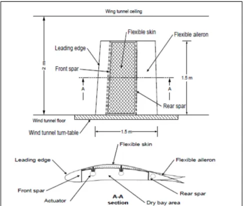
It was decided to design a wing with its cord and span length of 1.5m, as shown in Figure 2.2. These dimensions were chosen as they fitted the max model required dimensions in the wind
24
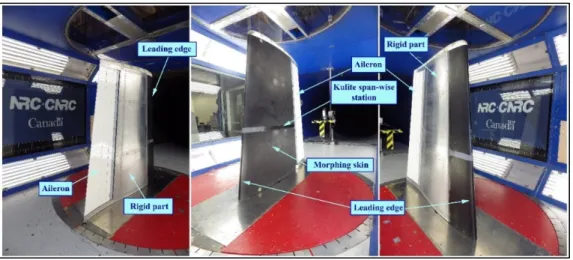
tunnel IAR-NRC. Actuation lines were placed at 32% and 48% of the chord. The rigid part of the wing was made of aluminium, but 20% to 65% of the wing’s upper skin was made flexible. Figure 2.3 shows the position of the morphing actuators inside the wing box and the position of the morphing wing tip on the real aircraft wing. The morphing skin was designed by the structures team at ETS. The wind tunnel testing was carried out in the IAR-NRC wind tunnel in Ottawa.
25
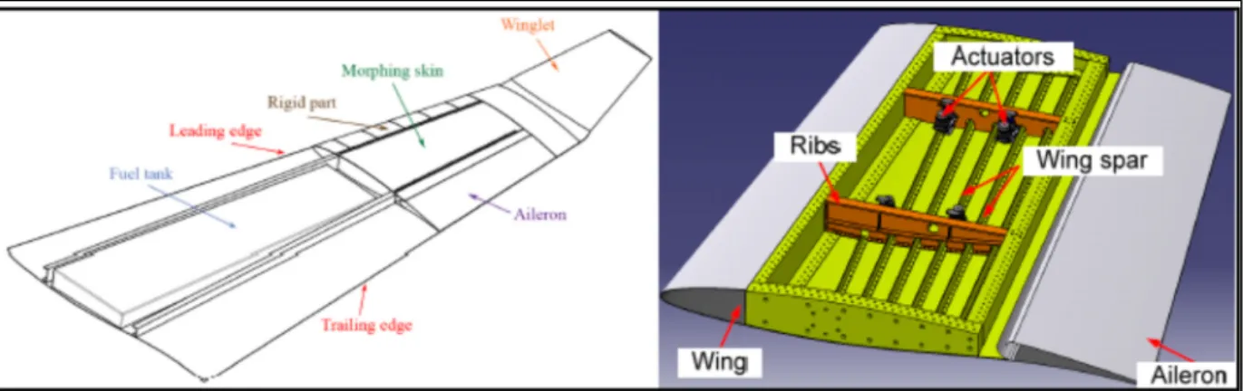
Figure 2.3 Position of the morphing wing tip on the real wing (left) and inside view of the wing box (right hand side)
Figure 2.4 shows the mounting of the actuator on the actuation line and its linkage to the flexible skin.
26
2.3 Features of the IAR-NRC wind tunnel testing facility in Ottawa
The IAR-NRC wind tunnel is used for subsonic aeronautical and industrial testing. It is used by commercial organizations, governments and universities for research and development in the field of aircraft aerodynamics, surface level aerodynamics, wind engineering and wind energy generation. The maximum speed of the IAR-NRC wind tunnel is 130 m/s. The dimensions of the test section are 1.9m×2.7m×5.2m (width×height×length).
2.4 Research Objectives
The global research objective of the CRIAQ MDO 505 project was to improve the laminar flows over a flexible wing skin. Laminar flows are improved by moving the laminar-to-turbulent transition point towards the trailing edge of a wing. The transition location is altered by morphing the upper flexible skin. Novel BLDC motor based morphing actuators were embedded under the wing’s flexible skin. The research objectives within in the CRIAQ MDO 505 project for this thesis are:
• Obtain the linear model of the novel morphing actuator based on the transfer function; • Design of an actuator nonlinear model;
• Design of an actuator control using classical control methods;
• Design of an actuator control using neural networks and fuzzy logic; and • Design an actuator controller using a heuristic optimization technique.
• Validation of the designed controller using bench testing and wind tunnel testing
2.5 Research approach and thesis organization
This thesis focuses on the research work done during the international CRIAQ MDO 505 project to develop a morphing wing for a commercial passenger aircraft. This research focuses