HAL Id: hal-00451912
https://hal.archives-ouvertes.fr/hal-00451912
Submitted on 25 Jun 2019HAL is a multi-disciplinary open access archive for the deposit and dissemination of sci-entific research documents, whether they are pub-lished or not. The documents may come from teaching and research institutions in France or abroad, or from public or private research centers.
L’archive ouverte pluridisciplinaire HAL, est destinée au dépôt et à la diffusion de documents scientifiques de niveau recherche, publiés ou non, émanant des établissements d’enseignement et de recherche français ou étrangers, des laboratoires publics ou privés.
Dynamic Balancing of the SCARA robot
Vigen Arakelian, Sébastien Briot
To cite this version:
Vigen Arakelian, Sébastien Briot. Dynamic Balancing of the SCARA robot. 17th CISM-IFToMM Symposium on Robot Design, Dynamics, and Control (RoManSy 2008), Jul 2008, Tokyo, Japan. �hal-00451912�
Dynamic Balancing of the SCARA Robot
Vigen Arakelian and Sébastien Briot
Département de Génie Mécanique et Automatique, L.G.C.G.M. – EA3913 Institut National des Sciences Appliquées (I.N.S.A.)
20 avenue des Buttes de Coësmes, CS 14315 F-35043 Rennes, France
[email protected] [email protected]
Abstract. This paper deals with the complete shaking force and shaking moment
balanc-ing of the four degrees of freedom SCARA robot. Dynamic reaction forces on the frame of the manipulator are eliminated by traditional approach making the total mass center of the moving links stationary. Reaction moments on the frame of the manipulator are eliminated by optimal control of the end-effector, which rotates with prescribed acceleration. A nu-merical simulation carried out on the software ADAMS illustrates that such a balanced SCARA robot transmits no inertia loads to surrounding, i.e. the sum of all ground bearing forces and their moments are eliminated.
1 Introduction
A primary objective in balancing a linkage is to remove or reduce the variable dynamic load it transmits to its frame and surrounding structures. Different approaches and solutions have been developed and documented (Lowen et al., 1983), (Arakelian et al., 2000), (Arakelian and Smith, 2005), but, despite its long history, mechanism balancing theory continues to develop and new approaches and solutions are constantly being reported. A new field for their application is the design of mechanical systems for fast manipulation, which are very efficient for advanced robotic applications. The cancellation of the inertia force (shaking force) transmitted to the robot frame can be achieved by traditional approach, which consists of fixation of the common center of mass of the moving links of the manipulator. The studies devoted to the inertia couple (shaking mo-ment) balancing of high-speed manipulators may be arranged in the following groups.
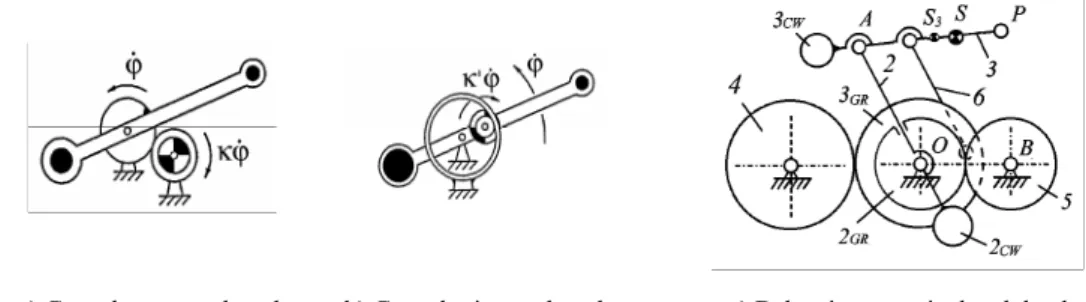
(i) Balancing by counter-rotations (Berkof, 1973), (Dresig et al., 1994), (Arakelian and Smith, 1999), (Herder and Gosselin, 2004). The aim of this approach is to connect the counterweights with planetary gear trains, which generate the counter-rotations (Fig. 1). The disadvantage of such a balancing is the need for the connection of gears to the oscillating links. The oscillations of the links of the mechanism will create noise unless expensive anti-backlash gears are used.
(ii) Balancing by adding four-bar linkages (Gosselin et al., 2004), (Ricard and Gosselin, 2000). This approach is achieved by building the mechanical system out of modules – four-bar linkages (Fig. 2). The four-bar linkages with prescribed geometric parameters allow the optimum redistribution of the moving mass to achieve the shaking moment balancing. The originality of
such a solution is the balancing of the shaking moment without the counter-rotations. However, the balancing by this method is only reached by a considerably complicated design.
a) Gears by external teeth b) Gears by internal teeth c) Balancing an articulated dyad
Figure 1. Balancing by counter-rotation (courtesy of C.M. Gosselin).
a) Balanced planar 2-DOF mechanism b) Balancing of a planar 3-DOF mechanism
Figure 2. Balancing by adding four-bar linkages (courtesy of C.M. Gosselin).
(iii) Balancing by optimum trajectory planning (Papadopoulos and Abu-Abed, 1994), (Fattah and Agrawal, 2006). In this case, the trajectory is planned in such a way that it brings to the minimal reactions on the base of the robot. Such an approach was applied to a redundant planar manipulator with 3 degrees of freedom and a planar 3-RRR parallel manipulator.
This paper deals with a new solution for shaking moment balancing of manipulators, which is based on the optimum control of the end-effector’s rotation about its axis. We illustrate the reac-tionless feature of such an approach through the four degrees of freedom SCARA robot.
2 SCARA robot: shaking force and shaking moment
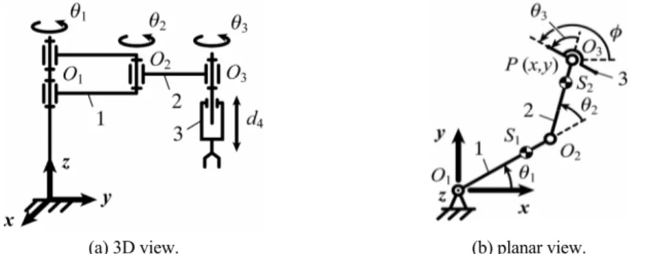
The SCARA (Selective Compliance Assembly Robot Arm) is a high-performance robot with relatively simple structure, which is composed of three revolute joints O1, O2 and O3 (Fig. 3) making it possible to move and orient the end-effector in the horizontal plane (x, y and φ) and one prismatic joint d4 allowing its movement in the vertical direction (z). The robot was developed in the laboratory of Professor Makino at Japon’s Yamanashi University (Makino and Furuya, 1982) and it is successfully applied in production industries. Today there are about 240 types of SCARA robots developed by 20 Companies.
Various studies was devoted to this architecture. The singularity analysis and workspace op-timization was discussed in the paper (Beiner, 1992). (Roth, 1985) studied this robot to achieve the optimal design for the links to minimize the pick-and-place motion. The dynamics was studied by (Ibrahim et al., 1989), as well as by (Padhy, 1992). (Chen et al., 2001) investigated the kine-matic calibration of the 4-DOF Scara robot. The vibration control for this robot was suggested in the study of (Kang et al., 1997).
(a) 3D view. (b) planar view.
Figure 3. Schematics of the SCARA robot developed at Yamanashi University.
It is well known that one of the fields of SCARA-type robots application is the fast pick-and-place manipulation. With increase of the manipulation speeds it becomes evident that the fast moving elements of mechanical systems bring about undesirable effects, such as vibration and noise. In this paper, for the first time, the dynamic balancing of the SCARA robot is studied.
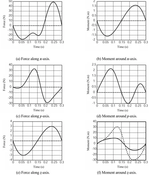
In order to estimate the variable dynamic loads transmitted to the frame of a SCARA robot we carried out the simulations on the software ADAMS. For this purpose, a standard cycle of pick-and-place motion (25×300 mm in 0.3 s) for fifth-order polynomial trajectory with the following initial and final locations xi = 0.15 mm, xf = -0.15 mm and yi = 0.2 mm, yf = 0.2 mm and φi = 83 deg., φf = 157 deg. orientation was selected. The geometric and inertia parameters of the robot are the following: lO1O2 = 0.125 mm, lO2O3 = 0.225 mm, lO1S1 = 0.0625 mm, lO2S2 = 0.1125 mm, m1 = 1.2 kg, m2 = 2 kg, m3 = 0.5 kg, I1 = 0.014 kg.m², I2 = 0.036 kg.m², I3 = 0.0126 kg.m², where lOiOj corresponds to the length of segment OiOj, lOiSi to the distance of the centre of masses Si from the joint centre Oi, mi is the mass of link i and Ii its axial moment of inertia.
Fig. 4 shows the shaking force and shaking moment variations of unbalanced robot (full line).
3 Shaking force and shaking moment balancing
In order to achieve the dynamic balancing of the SCARA robot, we first have to ensure that it is force-balanced, i.e. statically balanced. With regard to the vertical motion along the z axis, we can cancel the inertia forces by counterweights executing similar but opposite movements to the end-effector motion.
(a) Force along x-axis. (b) Moment around x-axis.
(c) Force along y-axis. (d) Moment around y-axis.
(e) Force along z-axis. (f) Moment around z-axis.
Figure 4. Variations of the shaking force and shaking moment unbalanced (full line) and statically balanced
(dotted line) robot.
Fig. 5 shows one of the design concepts carried out by pulley and cables. It should be noted that similar systems can be built by double slider-crank mechanisms, rhombic pantographs, and screw or cam systems.
Then, it is necessary to balance the shaking forces in the horizontal plane by making the total mass center of the moving links stationary (Fig. 4 – dotted lines). For this purpose, the following conditions may be achieved:
0 3 3S = O l , (1) 2 2 2 3 2 3lO O m lO S m = , (2) 2 1 3 2 1 1 1lOS (m m )lOO m = + , (3)
taking into account that the centers of masses of links 1 and 2 are not located between the centers of rotation but outside of them.
Figure 5. Balancing of the vertical inertia forces by using a cable and pulley arrangement.
However the force balancing leads to the important increase of the moving masses of the ro-bot, and as a result, its inertia couple (for the simulations, the following parameters for the balanced manipulator are used: lO1S1 = -0.117 mm, lO2S2 = -0.047 mm, m1 = 6.2 kg, m2 = 4.8 kg, I1 = 0.175 kg.m², I2 = 0.112 kg.m².). In Fig. 4 the shaking moment about the z axis is shown (dotted line). We can note that it is increased by a factor 3.
Now that the inertia force balancing is achieved, we have to consider the cancellation of the shaking moment.
The three angles of rotation of the SCARA robot (Fig. 3) are defined by the following rela-tionships: ⎟⎟ ⎟ ⎠ ⎞ ⎜⎜ ⎜ ⎝ ⎛ − + + − + + − − + ± − = − x l y x l l y x l l y x l y l O O O O O O O O O O O O O O 2 1 2 2 2 3 2 2 2 1 2 2 2 2 3 2 2 2 1 2 2 2 2 1 2 1 1 1 2 ) ( ) ( tan 2 θ , (4) 1 3 2 1 2 1 1 2 cos cos θ θ θ ⎟⎟− ⎠ ⎞ ⎜⎜ ⎝ ⎛ − = − O O O O l l x , (5) 2 1 3 φ θ θ θ = − − , (6)
where, x and y are the coordinates of the end-effector. The sign “±” in Eq. (4) shows that for the same end-effector position and orientation, there are two possible configurations (working modes) of the robot.
We can see from these equations that the angles θ1 and θ2 don’t depend on the angle θ3, i.e. the trajectory generation in the horizontal plan is defined only by the angles θ1 and θ2. It will be used for the shaking moment balancing.
(
1 2) (
3 1 2 3)
2 1
1θ&& + θ&& +θ&& + θ&& +θ&& +θ&&
=I I I
Msh , (7)
where θ&&i is the angular acceleration of link i, xSi, ySi the position of the centre of masses of link i along the x and y axes respectively, and x&&Si,y&&Si the acceleration of the centre of masses of link i along the x and y axes respectively.
In equation (7) we have a free parameter θ&&3 = d2θ3 dt2 , which defines the orientation of the end-effector between its initial and final positions but has not any influence to the prescribed trajectory.
In order to have a shaking moment of the robot equal to zero for the given trajectory, the ac-celeration θ&&3 for the period ti ≤ t ≤ tf, should vary by the following law:
(
)
2 1 3 2 1 2 1 1 3 θ θ θ θ θθ&& =− &&+ &&+ && − &&− &&
I I I
(8) The angular velocity θ&3(t) and angular displacement θ3(t) can be determined by simple
inte-gration of the obtained values of θ&&3.
Figure 6. Law of rotation of the end-effector ensuring the shaking moment balancing of the robot.
For examined robot with parameters given above and taking into account that after shaking force balancing, the axial inertia moment of the end-effector is equal to 0.0126 kg.m², we deter-mine the law of rotation of the end-effector (Fig. 6).
It should be noted that the moment of inertia of the end-effector is relatively small compared to the moments of inertia of robot links. Thus, to ensure the balancing of the shaking moment it is necessary that it turns several times during the motion of the robot in the horizontal plane.
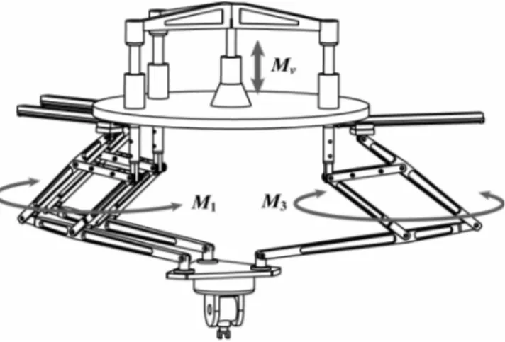
Finally, we would like to note that the suggested approach can be also applied to others posi-tion-orientation decoupled manipulators. Fig. 7 shows a new architecture of PAMINSA manipulator (Arakelian et al., 2006), (Briot, 2007) with 6 degrees of freedom, in which the gen-eration of translations in the horizontal plane is achieved by the use of the rotating actuators M1,
M3 and the vertical translations by the linear actuator Mv. The orientation of the end-effector is carried out by the serial wrist mounted on the platform.
The shaking moment on the frame of this manipulator can be eliminated by optimal control of the serial wrist with prescribed rotation velocities. Our future work will consist in the detailed study of such a balancing with numerical simulations carried out using ADAMS software.
Figure 7. PAMINSA with 6 DOF, in which the Cartesian displacements are carried out by the parallel
struc-ture and the orientation by the serial wrist mounted on the platform.
Although the shaking force and shaking moment are eliminated, in practice there are small deviations from the ideal zero reaction. Sources of such deviations include manufacturing errors, neglected friction and clearances in the joints and drive actuators, as well as manipulator unbal-ancing due to a payload. However, in all these cases the proposed balunbal-ancing method will eliminate the most significant base reactions due to robot accelerating links.
4 Conclusion
A new field for shaking force and shaking moment balancing is the design of fast parallel ma-nipulators, which are very efficient for advanced robotic applications. In this paper, the shaking force and shaking moment balancing method is developed for the SCARA-type robots with 4 degrees of freedom. The shaking forces of the manipulator in the horizontal plan are eliminated by optimum redistribution of masses making the total mass center of the moving links stationary. With regard to the vertical inertia forces, the opposite motion of the end-effector and the counter-weights is applied. The shaking moments on the frame of the manipulator are eliminated by optimal control of the end-effector, which rotates with prescribed velocity. Numerical simulations carried out on the software ADAMS showed that after such a balancing, the manipulator trans-mits no inertia loads to its surroundings, i.e. the sum of all ground bearing forces and their moments are eliminated.
The advantage of such a balancing is its simplicity. The complete balancing of the shaking moment is achieved without important design modifications. We believe that the balancing of manipulators by means of optimum control of the end-effector is a very promising approach to dynamic performance improvement.
Bibliography
Arakelian, V.H., and Smith, M.R. (1999). Complete shaking force and shaking moment balancing of link-ages. Mechanism and Machine Theory. 34(8). 1141-1153.
Arakelian, V.H., Dahan, M., and Smith, M.R. (2000). A historical review of the evolution of the theory on balancing of mechanisms. In Proceedings of the International symposium on history of machines and
mechanisms. Dordrecht: Kluwer Academic Publishers. 291-300.
Arakelian, V.H., and Smith, M.R. (2005). Shaking force and shaking moment balancing of mechanisms: a historical review with new examples. Transactions of the ASME, Journal of Mechanical Design. 127. 334-339.
Arakelian, V., Maurine, P., Briot, S., and Pion, E. (2006). Parallel robot comprising means for setting in motion a mobile element split in two separate subassemblies. Patent WO 2006/021629, January 27. Beiner, L. (1972). Singularity avoidance for SCARA robots. Robotics and Automation Systems. 10. 63-63. Berkof, R.S. (1973). Complete fore and moment balancing of inline four-bar linkages. Mechanism and
Ma-chine Theory. 8(3). 397-410.
Briot S. (2007). Analysis and optimization of a new family of parallel manipulators with decoupled motions. Ph.D. Thesis, INSA, Rennes, France.
Chen, I.M., Yang, G., Tan, C.T., and Yeo, S.H. (2001). Local POE model for root kinematic calibration.
Mechanism and Machine Ttheory, 36(11-12). 1215-1239.
Dresig, H., Naake, S., and Rockausen L. (1994). Vollständiger und harmonischer Ausgleich ebener Mechanismen,VDI Verlag, Düsseldorf, 73p.
Fattah, A., and Agrawal, S.K. (2006). On the design of reactionless 3-DOF planar parallel mechanisms.
Mechanism and Machine Theory. 41(1). 70-82.
Gosselin, C.M., Cote, G., and Wu, Y. (2004). Synthesis and design of reactionless tree-degree-of-freedom parallel mechanisms. IEEE Transactions on Robotics and Automation. 20(2). 191-199.
Herder, J.L., and Gosselin, C.M. (2004). A counter-rotary counterweight for light-weight dynamic balancing. In Proceedings of ASME 2004 DETC/CIEC Conference, September 28 – October 2, Salt Lake City,
Utah, USA. 659-667.
Ibrahim, M.Y., Cook, C., and Tieu, A.K. (1989). Dynamics characteristics of a SCARA robot subject to NC2 velocity trajectories with different payloads. Robotics and Computer-Integrated Manufacturing, 6(3), 259-264.
Kang, Z.B., Chai, T.Y., Oshima, K., Yang, J.M., and Fujii, S. (1997). Robust vibration control for SCARA-type robot manipulators. Control Eng. Pratice. 5(7). 907-917.
Lowen, G.G., Tepper, F.R., and Berkof, R.S. (1983). Balancing of linkages – an Update. Mechanism and
Machine Theory. 18(3). 213-230.
Makino, H., and Furuya, N. (1982). SCARA robot and its family. In Proceedings of the 3rd International
Conference on Assembly Automation, Boeblingen, Germany. 433-444.
Padhy, S.K. (1992). On the dynamics of SCARA robot. Robotics and Automation Systems. 10. 71-78. Papadopoulos, E., and Abu-Abed, A. (1994). In Proceedings of the IEEE International Conference on
Ro-botics and Automation, San Diego, CA. 1554-1559.
Ricard, R., and Gosselin, C.M. (2000). On the design of reactionless parallel manipulators. In Proceedings of
the ASME 2000 DETC/CIEC Conference, Baltimore, Maryland, September 10-13. 1-12.
Roth, B. (1985). Control and mechanics of simple manipulator systems. In: Hanfusa and Inoue, eds.,