HAL Id: hal-00874942
https://hal.archives-ouvertes.fr/hal-00874942
Submitted on 19 Oct 2013
HAL is a multi-disciplinary open access
archive for the deposit and dissemination of
sci-entific research documents, whether they are
pub-lished or not. The documents may come from
teaching and research institutions in France or
abroad, or from public or private research centers.
L’archive ouverte pluridisciplinaire HAL, est
destinée au dépôt et à la diffusion de documents
scientifiques de niveau recherche, publiés ou non,
émanant des établissements d’enseignement et de
recherche français ou étrangers, des laboratoires
publics ou privés.
Architecture-Based Conformance Testing
Elena Leroux, Flavio Oquendo, Qin Xiong
To cite this version:
Elena Leroux, Flavio Oquendo, Qin Xiong. Architecture-Based Conformance Testing. The Eighth
International Conference on Software Engineering Advances (ICSEA’13), Oct 2013, Venice, Italy.
pp.55-64. �hal-00874942�
Architecture-Based Conformance Testing
Elena Leroux, Flavio Oquendo, and Qin Xiong IRISA, University of South-Brittany, France E-mails: {elena.leroux | flavio.oquendo | qin.xiong}@irisa.fr
Abstract—In the last two decades, software architecture has played a central role in the development of software systems. It provides a high-level description for large-size and complex systems using suitable abstractions of the system’s components and their interactions. In our work, the software architecture is described using a formal Architec-ture Description Language (ADL) designed in the ArchWare European Project, π-ADL-C&C. One of the purposes of this ADL is to allow formal validation of an implemented system with respect to its architectural model. In this paper, we propose a conformance testing approach for validating a software system with respect to its architecture. The architectural abstract test cases are derived from an Input-Output Symbolic Transition System (IOSTS) representing the architecture structure and behaviors, which are then translated into concrete test cases to be executed on the system under test. To illustrate our approach we use the coffee machine example.
Keywords—Software Architecture, Architecture Description
Language, Architectural Conformance Testing, Validation
I. Introduction
During the past years a continuous growth, in size and com-plexity, of software and hardware systems has been observed. The problems, which were important in the pass, and which are related to a code development, e.g., the choice of data structure and algorithms, became less important than the ones related to the system design. This is not only due to the increased amount of code, but also to the need to distribute different components of the system and to have them interact in complex ways. To deal with these problems and to rise the level of abstraction at which software is conceived and developed, a software architecture has emerged. It was rapidly considered as an important sub-discipline of software engineering [1]. Software architecture allows developers: (1) to abstract away the details of the individual components of a system, (2) to represent a system as sets of components with associated connectors that describe the interactions (a) among these components, and (b) between the components and the environment, and (3) to guide the system design and evolution. In order to describe the software architecture of a system, a set of formal and semi-formal languages has been proposed [2], [3]. These ADLs help specify an architecture according to different viewpoints. The two following viewpoints are frequently used at a runtime perspective in the software architecture discipline.
The structural viewpoint is specified in terms of: (1) compo-nents (i.e., units of computation of a system), (2) connec-tors (interconnections among components for supporting
their interactions), and (3) configurations of components and connectors. Thereby, an architecture description, from a structural viewpoint, should provide a formal specifi-cation of the architecture in terms of components and connectors, and how they are composed together.
The behavioral viewpoint is specified in terms of: (1) actions a
system executes or participates in, (2) relations among ac-tions to specify behaviors, and (3) behaviors of components and connectors, and how they interact.
An ADL challenge is the ability of a language to enable vali-dation of designed systems very early in the software life cycle in addition to verification all along the software process. The
π-ADL [4] language has been designed in order to meet this challenge. π-ADL is an executable specification language that allows formal description of software architectures of a system under development. A virtual machine of π-ADL runs specifi-cations of the software architecture and enables its validation by simulation and testing as described in this paper.
The analysis and validation, by using, for example, software testing techniques, of software systems play a crucial role in the system development process. That is one of the reasons of the raising interest to the use of the architectural models in order to test systems behaviors with respect to their early architectural specification. Software testing [5] is a process consisting in the dynamic verification of system behaviors, which is performed by observing the execution of the system on a selected test case. Several contributions [6]–[13] have been proposed to tackle the problem of the validation of software systems by means of architectural testing. The brief overview of them is done in Section VI of this paper.
In this paper, we focus on model-based conformance
test-ing [14], [15], which permits to derive test cases from a model
representing the behavior of a software system, in order to check that this system fulfills its behavior. We use IOSTS as a model, which we generate from a formal architectural specification designed in the π-ADL language. The goal is to propose an approach for validation of software systems using their architectural specifications, and to illustrate its feasibility with a simple example.
The remainder of this paper is structured as follows: Sec-tion II presents the π-ADL language, which is used for ar-chitecture design, and a working example, used all along this paper, for the demonstration of our approach. Section III briefly describes the IOSTS formalism, which is used to model an ar-chitectural π-ADL specification and abstract test cases derived from this specification. Section IV presents our approach ex-plaining how to generate test cases from a π-ADL architecture and execute them on a black-box system under test. Section V lists the tools used or/and developed to support our approach. Section VI summarizes our work, positions it with respect to the other works done in the field of the software architecture-based testing and gives a brief overview of related work. Section VII closes the paper with summary remarks.
II. The π-Architecture Description Language In this section, we briefly present π-ADL, which we are using for the architecture description of a system under development, and we illustrate it with a working example of a coffee machine.
A. Overview
The π-ADL language [4], designed in the ArchWare Euro-pean Project, is a formal, well-founded theoretically language
based on the higher-order typed π-calculus [16]. It supports de-scription of software architectures from a runtime perspective. Moreover, π-ADL has a virtual machine allowing execution of architectural specifications, and therefore, the validation of a software architecture by simulation is enabled. In the following, we briefly explain how the π-ADL language can be used for the formal definition of a software architecture.
In π-ADL, an architecture is described in terms of compo-nents, connectors, and their composition.
Components are described in terms of external ports and an
internal behavior. Their architectural role is to specify computational elements of a software system. The focus is on computation to deliver system functionality. Ports are described in terms of connections between a component and its environment. Their architectural role is to put together connections providing an interface between the component and its environment. Protocols may be enforced by ports and among ports.
Connectors are basic interaction points. Their architectural
role is to provide communication channels between two architectural elements. A component can send or receive values via connections. They can be declared as output connections (values can only be sent), input connections (values can only be received), or input-output connections (values can be sent or received).
From a black-box perspective, only ports (with their con-nections) of components and connectors and values passing through connections are observable. From a white-box perspec-tive, internal behaviors are also observable.
π-ADL consists of a family of related ADLs. The π-ADL-C&C language describes an architecture at an abstract high level. This language is user-friendly, and it allows rapid design of architectures using the notions of component and connector. The π-ADL-Spec language is a canonical form of π-ADL. Finally, the π-ADL.NET language is a low level ADL, that makes possible an execution of architectural specification as it is equipped with a virtual machine.
B. Working Example
In this section, we present a working example of a simple coffee machine, which will be used all along the paper. Fig.1 shows the abstract architecture of the coffee machine in terms of components and connectors. This coffee machine accepts coins (thought the Coin(Natural) connector), the request for a bev-erage (thought the PressButton() connector), and the request for a command canceling (thought the Cancel() connector), and then either delivers the beverage (thought the Deliver() connec-tor) or returns money back (thought the Return(Natural) con-nector). It consists of two components: Payment and Beverage. A request for a beverage is received by the Beverage compo-nent from the user interface of the coffee machine. The purpose of this component is (1) to stock the information about the availability and the price of a coffee, (2) to wait until the beverage button is pressed, (2) to communicate the price to the
Payment component, (3) to prepare a coffee, and (4) to deliver
it to a customer. The Beverage component serves the coffee whenever the two following conditions are satisfied: first, a customer has paid enough (this information should be received from the Payment component), and second, coffee is not out
Coin(Natural) Cancel() PressButton() Return(Natural) Deliver() P a id () / P a id () N o tP a id () / N o tP a id () S en d P ri ce (N a tu ra l) / R ec ei ve P ri ce (N a tu ra l) Coffee Machine Payment Beverage
Fig. 1. The coffee machine architecture.
of stock. If the first condition is not satisfied, the component
Beverage waits for another request for coffee and then checks
again if the payment is sufficient. If the second condition is not satisfied, then the delivery of coffee is impossible, and the
Beverage component is blocked.
The requests for a payment and for a command cancel-ing comcancel-ing from the user interface of the coffee machine are accepted by the Payment component. This component allows (1) to memorize the amount of money already paid by the customer, the number of coins inserted into the coffee machine, and the price of a coffee received form the Beverage component, (2) to communicate the information about sufficient/insufficient payment to the Beverage component, (3) to return the money back if the Cancel button has been pressed, or if the customer inserted more coins than authorized by the coffee machine, and (4) to return the difference between the price and the paid amount in the case of a coffee delivery.
Note that, the Beverage and Payment components com-municate not only with their environment, but also with themself. Indeed, the Beverage component sends the price of a coffee through the SendPrice(Natural) connector to the
Payment component. The latter receives the price through
the ReceivePrice(Natural) connector. Moreover, the Payment component notifies the Beverage component if the customer has paid enough or not using the Paid() and NotPaid() connectors.
C. Architecture Description using π-ADL-C&C
In the previous section, we have informally described the structure and behavior of the coffee machine. In this section, we explain how this structure and behavior can be formalized using the π-ADL-C&C language. We begin with the description of two components of the coffee machine, namely the Beverage (see Fig.2) and the Payment (see Fig.3) components.
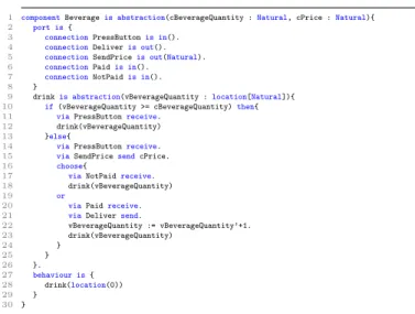
1) The beverage component. The Beverage component,
shown on Fig.2, is declared as an abstraction (see line 1) with two Natural parameters: (1) cBeverageQuantity indicating the quantity of the beverage in the coffee machine, (2) cPrice indicating the price of the beverage. The external ports of this component are shown on lines 3-9, and described in terms
1 componentBeverageis abstraction(cBeverageQuantity :Natural, cPrice :Natural){ 2 port is{
3 connectionPressButtonis in(). 4 connectionDeliveris out(). 5 connectionSendPriceis out(Natural). 6 connectionPaidis in().
7 connectionNotPaidis in().
8 }
9 drinkis abstraction(vBeverageQuantity :location[Natural]){
10 if(vBeverageQuantity >= cBeverageQuantity)then{
11 viaPressButtonreceive.
12 drink(vBeverageQuantity)
13 }else{
14 viaPressButtonreceive.
15 viaSendPricesendcPrice.
16 choose{
17 viaNotPaidreceive.
18 drink(vBeverageQuantity)
19 or
20 viaPaidreceive.
21 viaDeliversend.
22 vBeverageQuantity := vBeverageQuantity’+1. 23 drink(vBeverageQuantity) 24 } 25 } 26 }. 27 behaviour is{ 28 drink(location(0)) 29 } 30 }
Fig. 2. The beverage component expressed in π-ADL-C&C.
of connections: PressButton, Paid, NotPaid, and SendPrice,
Deliver, where the three first connections permit to receive
the information from the environment (they are declared as input connections by using the keyword in) and the two last ones allow to send the information to the environment (they are declared as output connections by using the keyword out). Notice that, the SendPrice connection permits to send one value of the Natural type (see line 6) in order to be able to communicate the price of the beverage.
1 componentPaymentis abstraction(cCoinNumber:Natural){ 2 port is{
3 connectionCoinis in(Natural). 4 connectionReturnis out(Natural). 5 connectionCancelis in().
6 connectionReceivePriceis in(Natural). 7 connectionPaidis out()
8 connectionNotPaidis out() 9 }.
10 payingis abstraction(
11 cCoinNumber:Natural,
12 vPaid:location[Natural],
13 vCoinNumber:location[Natural],
14 vPrice:location[Natural]
15 ){ 16 choose{
17 ifvCoinNumber < cCoinNumberthen{
18 viaCoinreceivepCoin :Natural.
19 vPaid := vPaid’+pCoin.
20 vCoinNumber := vCoinNumber’+1.
21 paying(cCoinNumber, vPaid, vCoinNumber, vPrice)
22 }else{
23 viaReturnsendvPaid.
24 paying(cCoinNumber,location(0),location(0),location(0))
25 }
26 or
27 viaReceivePricereceivepPrice :Natural.
28 vPrice := pPrice.
29 paying(cCoinNumber, vPaid, vCoinNumber, vPrice)
30 or
31 viaCancelreceive.
32 viaReturnsendvPaid.
33 paying(cCoinNumber,location(0),location(0),location(0))
34 or
35 ifvPaid >= vPricethen{
36 viaPaidsend.
37 viaReturnsend(vPaid-vPrice).
38 paying(cCoinNumber,location(0),location(0),location(0))
39 }else{
40 viaNotPaidsend.
41 paying(cCoinNumber, vPaid, vCoinNumber, vPrice)
42 }
43 }
44 }. 45 behaviour is{
46 paying(cCoinNumber,location(0),location(0),location(0))
47 } 48 }
Fig. 3. The payment component expressed in π-ADL-C&C.
The behavior of the Beverage component is shown on lines 27-29, and described as a call to the drink abstraction
carry-ing 0. The value 0 initializes the variable vBeverageQuantity memorizing the quantity of beverage already used. The body of the drink abstraction describes formally the behavior of the
Beverage component of the coffee machine, explained informally
in Section II-B. More precisely, the Beverage component verifies if the quantity of beverage is sufficient or not (see line 10). In the both cases above, it lets the customer to press the button (see lines 11 and 14), but (1) in the last case (the quantity of beverage is insufficient), the component is blocked (see the call to the same abstraction drink with the same value of parameter vBeverageQuantity on line 12), while (2) in the first case (the quantity of beverage is sufficient), the component communicates the price of the beverage using the
SendPrice connection (see line 15), and then: (a) either returns
into its initial state (see the call to the abstraction drink on line 18), if it has received the notification of insufficient payment through the NotPaid connection (see line 17), or (b) delivers the beverage using the Deliver connection (see line 21) and increases
vBeverageQuantity by one (see line 22), if it has received the
notification of sufficient payment through the Paid connection (see line 20), and comes back to its initial state (see the call to the abstraction drink on line 23).
2) The payment component. The formal description of the Payment component is given on Fig.3 and is similar to one of
the Beverage component. Therefore, we do not detail it.
3) The architecture of the coffee machine. The
architec-ture of the coffee machine is formally described in Fig.4. It is an abstraction whose behavior (see 2-12) is composed of two instantiated components Beverage(10,3) and Payment(10) (see lines 3-7). These components communicate via the unified connections shown on lines 8-10.
1 architectureCoffeeMachineis abstraction() { 2 behaviour is{ 3 compose{ 4 beverageisBeverage(10, 3) 5 and 6 paymentisPayment(10) 7 }where{
8 payment::ReceivePriceunifiesbeverage::SendPriceand
9 payment::Paidunifiesbeverage::Paidand
10 payment::NotPaidunifiesbeverage::NotPaid
11 }
12 } 13 }
Fig. 4. The architecture of a coffee machine in π-ADL-C&C.
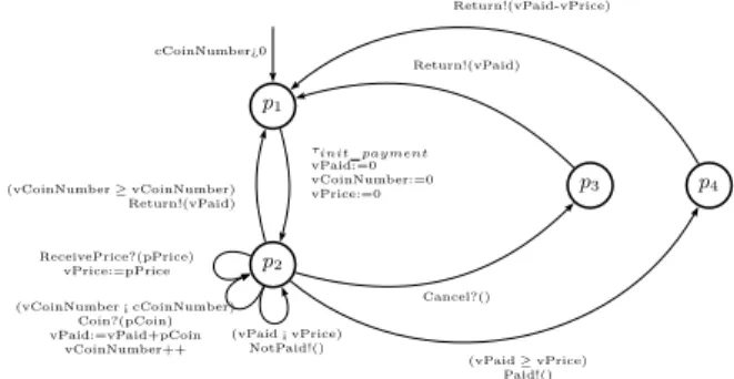
III. Underlying Model for Test Case Generation In this paper, we are interested in conformance testing of a system under development with respect to its architectural specification expressed at the user-level using π-ADL-C&C language. For test cases generation using STG [17], [18], we automatically translate a high-level architectural specification into the low-level model called IOSTS. We use IOSTS for describing architectural specifications, test purposes, and test cases, and assume that the black-box implementation can be described by an IOSTS of which only the external interface is known. The formal syntax and semantics of IOSTS are defined in [19]. The intuitive explanation is given below using the example depicted in Fig.5, which represents the payment component of the coffee machine. Notice that, the beverage component can also be modeled by IOSTS as it is shown in Fig.5.
An IOSTS is made up of locations, for example, p1, p2,
The transitions are labeled with actions, guards, and variable
assignments. For example, the transition with origin p2and
des-tination p2 has the guard (vCoinN umber < cCoinN umber),
the input action Coin? carrying the data pCoin from the envi-ronment, and two variable assignments vP aid := vP aid+pCoin and vCoinN umber + +. The set of actions is partitioned into three disjoint subsets of input, output, and internal actions. The input/output actions interact with the environment and may carry data from/to it, while internal actions are used for internal computations. By convention, the names of input (resp. output) actions end with “?” (resp. “!”). The IOSTS in Fig.5 has two inputs: Coin? and Cancel?, three outputs: Paid!,
NotPaid!, Return!, and one internal action: τinit payment. It
operates with symbolic data consisting of variables, constants, and parameters. Intuitively, variables are data to compute with,
constants are symbolic constants, and parameters are data to
communicate with the environment. Note that the scope of parameters is only a transition labeled by an action, which carries these parameters. Thus, if the value of a parameter should be used in later computations, it should be memorized through an assignment to a variable.
p1 p2 p3 p4 cCoinNumber¿0 τinit payment vPaid:=0 vCoinNumber:=0 vPrice:=0 (vCoinNumber ≥ vCoinNumber) Return!(vPaid) ReceivePrice?(pPrice) vPrice:=pPrice (vCoinNumber ¡ cCoinNumber) Coin?(pCoin) vPaid:=vPaid+pCoin vCoinNumber++ (vPaid ¡ vPrice) NotPaid!() Cancel?() Return!(vPaid) (vPaid ≥ vPrice) Paid!() Return!(vPaid-vPrice)
Fig. 5. The payment component modelled by an IOSTS.
b1
b2
b3
b4
b5 (cBeverageQuantity¿0) and (cPrice¿0)
τinit beverage vBeverageQuantity:=0 (vBeverageQuantity ¡ cBeverageQuantity) PressButton?() SendPrice!(cPrice) Paid?() (vBeverageQuantity ≥ cBeverageQuantity) PressButton?() NotPaid?() Deliver!() vBeverageQuantity++
Fig. 6. The beverage component modelled by an IOSTS.
Informal semantics. Consider the IOSTS (cf. Fig.5)
rep-resenting the Payment component of the coffee machine. The payment starts in the location p1 with some value of
the cCoinNumber constant satisfying the initial condition
cCoinN umber >0, that is, the number of coins accepted by the coffee machine is strictly positive. Then, it fires the transition labeled by the internal action τinit payment, assigns the three
variables: vPaid storing the amount already paid, vCoinNumber memorizing the number of coins inserted into the machine, and
vPrice storing the price of the beverage, to 0, and reaches the
location p2. Next, the Payment component expects either:
– a coin, denoted by the Coin? input action that carries in the
pCoin parameter the value of the inserted coin. The
vari-ables vPaid and vCoinNumber are increased respectively by pCoin and by 1. Note that the Coin? action can be executed only in the case, where the number of the already inserted coins is less than the value of the cCoinNumber constant. Otherwise, the payment component returns the amount already paid (through the Return!(vPaid) output action) and moves back to the initial location p1. Or
– the price of a beverage, denoted by the ReceivePrice? input action that carries in pPrice the cost of the beverage, the variable vPrice is initialized to the value of pPrice. In the two cases above, the machine stays in the location
p2. If the payment is enough, i.e., vPaid ≥ pPrice, the
pay-ment component, first of all, emits the Paid!() output action and moves to the location p4, and then returns (through the
Return!(pPrice − vPaid) output action) the difference between
the paid amount and the cost of a beverage, i.e., pPrice − vPaid, and moves to the initial location p1. Otherwise, the payment
component sends the NotPaid!() output action and stays in the location p2. Note that in the location p2, the Cancel? input
action can be received, which signifies that the Cancel button has been pressed. In this case, the payment component returns the amount already paid (through the Return!(vPaid) output action) and moves back to the initial location p1.
Formal semantics. A state s is a pair hl, ϑi, where l is
a location and ϑ is a valuation of the constants and vari-ables, e.g., s = hCoin, cCoinNumber=10, vPrice=3, vPaid=2,
vCoinNumber=4i. An initial state s0
= hl0
, ϑ0
i is a state where
l0 is the initial location, and ϑ0
is a valuation of the constants and variables which satisfy the initial condition. We denote by S (resp. S0
) the set of all states (resp. initial states). A
valued action α is a pair ha, ωi, where a is an action and ω is a
valuation of the parameters of a, e.g., α = hCoin, pCoin = 1i or α = hτinit paymenti. We denote by Λ = Λ?∪ Λ!∪ Λτ the
set of valued actions, which is partitioned into three subsets of valued input, valued output, and internal actions. Next, we define the transition relation → as the set of triples hs, α, s′i,
where s = hl, ϑi, s′ = hl′, ϑ′i are states and α = ha, ωi
is a valued action. Here, (1) ϑ and ω are valuations of the constants, variables, and parameters, which satisfy the guard of a transition t with the origin l and the destination l′ that
is labeled with the action a, and (2) ϑ′ is the new valuation
of the variables and constants obtained from ϑ by the variable assignments of t.
Definition 1: A behavior β is a sequence of states and valued
actions starting from an initial state and following the transition relation, i.e., β : s0 α→ s1 1 α2 → s2. . . sn−1 α→ sn n where → is the transition relation, s0 ∈ S0
, and for all i ∈ [1, n]: si∈ S, αi∈ Λ.
To describe observable behaviors of IOSTS we define the rela-tion ⇒ as follows: – s ⇒ sε ′ , (s = s′) ∨ (∃s 0, . . . , sn ∈ S. s = s0 τ1 → s1. . . sn−1 τn
→ sn= s′), where for all i ∈ [1, n]: τi∈ Λτ;
– s⇒ sα ′, ∃s 1, s2∈ S. s ε ⇒ s1 α → s2 ε ⇒ s′, where α ∈ Λ? ∪Λ! .
Definition 2: An observable behavior β is a sequence of
states and valued input or output actions, i.e., β : s0 α1
⇒ s1 α2 ⇒ s2. . . sn−1 αn ⇒ sn where s 0 ∈ S0
, and for all i ∈ [1, n]:
si∈ S, αi∈ Λ
?
∪ Λ!
.
Definition 3: A trace σ is the sub-sequence of an observable
behavior β : s0 α1 ⇒ s1 α2 ⇒ s2. . . sn−1 αn ⇒ sn, which consists of
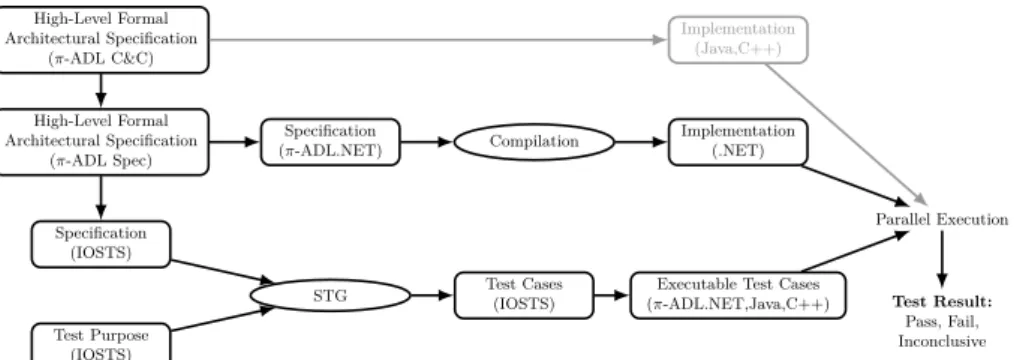
High-Level Formal Architectural Specification (π-ADL C&C) High-Level Formal Architectural Specification (π-ADL Spec) Specification (π-ADL.NET) Compilation Implementation (.NET) Implementation (Java,C++) Specification (IOSTS) Test Purpose (IOSTS)
STG Test Cases(IOSTS) (π-ADL.NET,Java,C++)Executable Test Cases
Parallel Execution
Test Result:
Pass, Fail, Inconclusive
Fig. 7. Outline of the approach.
valued input or output actions, i.e., σ : α1α2. . . αnwhere for
all i ∈ [1, n]: αi∈ Λ
?
∪ Λ!
.
A. Conformance Relation
The conformance relation defines the set of system’s imple-mentations which are correct with respect to its architectural specification. Intuitively, an implementation is conformant to a specification if for each trace of the specification, the implemen-tation produces only outputs, which are allowed by the spec-ification. To define the conformance relation formally, we first define the set of states in which an IOSTS M can be after the observable trace σ: (M af ter σ), {s ∈ S | ∃s0
∈ S0
. s0 σ
⇒ s}, and the set of valued output (resp. input) actions which can be generated by M when it is in some state s among the set of states ˜S: Out( ˜S), {α ∈ Λ!
| ∃s ∈ ˜S. s→} (resp. In( ˜α S), {α ∈ Λ?
| ∃s ∈ ˜S. s→}), where sα →α , ∃s′ ∈ S. s→ sα ′. Finally,
denote by T races(M ) the set of traces of M . Note that if a trace σ does not belong to T races(M ) then Out(M af ter σ) and In(M af ter σ) are the empty set. For two IOSTS M1,
M2 and each trace σ ∈ T races(M1) \ T races(M2) we define
Out(M2 af ter σ) and In(M2 af ter σ) to be the empty set.
Definition 4: The conformance relation between two IOSTS IU T and Spec with fixed, identical constants is defined as follows: (IU T conf Spec) , ∀σ ∈ T races(Spec).Out(IU T af ter σ) ⊆ Out(Spec af ter σ).
IV. Approach for Architecture Validation In this section, we describe the approach, which we use for the architecture validation of a system under development. This approach is depicted in the Fig.7 and presented below.
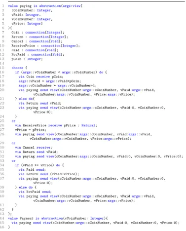
A. From π-ADL-C&C to π-ADL-Spec
The first step of our approach consists in the transformation of a high-level architectural specification described in π-ADL-C&C into its canonical form in π-ADL-Spec. To illustrate this transformation we use the payment component whose π-ADL-C&C code is shown in Fig.3. The result of the transformation is shown on Fig.8.
a) The components and their internal behaviors
de-clared as abstractions are translated into the individual abstrac-tions of behaviors. These individual abstracabstrac-tions can be later instantiated as behaviors by an application. Moreover, to enable a recursive call of an abstraction instance, this abstraction should be declared as a recursive abstraction in the π-ADL-Spec language by using the keyword “recursive”. For example, the payment component (see lines 1-44 of Fig.3) corresponds to its individual abstraction shown on lines 43-45 of Fig.8;
and its internal behavior “paying” (see lines 12-45 of Fig.3) corresponds to the recursive abstraction shown on lines 1-42 of Fig.8. Notice that, the parameters of components and internal behaviors are the same as the parameters of the corresponding individual abstractions. See, for example, the line 1 of Fig.3 and the corresponding line 43 of Fig.8.
1 recursive valuepaying =abstraction(
2 cCoinNumber:Natural,
3 vPaid:location[Natural],
4 vCoinNumber:location[Natural],
5 vPrice:location[Natural]
6 ){
7 valueCoin =connection(Natural); 8 valueReturn =connection(Natural); 9 valueCancel =connection();
10 valueReceivePrice =connection(Natural); 11 valuePaid =connection();
12 valueNotPaid =connection(); 13
14 choose{
15 if(’vCoinNumber < cCoinNumber)then{
16 viaCoinreceivepCoin :Natural;
17 vPaid := ’vPaid+pCoin;
18 vCoinNumber := ’vCoinNumber+1;
19 paying(cCoinNumber, vPaid, vCoinNumber, vPrice)
20 }else{
21 viaReturnsendvPaid;
22 paying(cCoinNumber,location(0),location(0),location(0))
23 }
24 or
25 viaReceivePricereceivepPrice :Natural;
26 vPrice := pPrice;
27 paying(cCoinNumber, vPaid, vCoinNumber, vPrice)
28 or
29 viaCancelreceive;
30 viaReturnsend’vPaid;
31 paying(cCoinNumber,location(0),location(0),location(0))
32 or
33 if(’vPaid >= ’vPrice)then{
34 viaPaidsend;
35 viaReturnsend(’vPaid-’vPrice);
36 paying(cCoinNumber,location(0),location(0),location(0))
37 }else{
38 viaNotPaidsend;
39 paying(cCoinNumber, vPaid, vCoinNumber, vPrice)
40 }
41 } 42 };
43 valuePayment =abstraction(cCoinNumber:Natural){
44 paying(cCoinNumber,location(0),location(0),location(0))
45 }
Fig. 8. The payment component expressed in π-ADL-Spec.
b) The connections, declared in a π-ADL-C&C
compo-nent (see for example, lines 3-8 of Fig.3), should be declared in the scope of a π-ADL-Spec abstraction in which they are used (see lines 7-12 of Fig.8). Notice that, the syntax for the declaration of a connection has been changed. Moreover, in the π-ADL-Spec language we do not need to specify if the connection is used to receive or to send information from/to its environment.
B. From π-ADL-Spec to π-ADL.NET
In order to obtain a system ready to be compiled and executed, we need to transform the π-ADL-Spec specification into the π-ADL.NET code. This section briefly outlines some important points of this transformation (see Fig. 8 and 9).
a) For each abstraction of π-ADL-Spec, its list of
pa-rameters, containing more than one parameter (see for example, lines 2-5 of Fig.8), is encapsulated as a value of the view type in the π-ADL.NET code (see respectively lines 1-5 of Fig.9). Each value of the view type view[label1:T1,...,labeln:Tn]
is a view view(label1=v1,...,labeln=vn), where for i ∈ [1, n],
each value vi has type Ti, and each label labeli has the same
name as its corresponding parameter in the π-ADL-Spec code. The reason is that the π-ADL.NET language does not support a list of parameters for a value passing.
1 valuepayingis abstraction(args:view[
2 cCoinNumber:Integer,
3 vPaid:Integer,
4 vCoinNumber:Integer,
5 vPrice:Integer]
6 ){
7 Coin :connection[Integer];
8 Return :connection[Integer];
9 Cancel :connection[Void];
10 ReceivePrice :connection[Integer];
11 Paid :connection[Void];
12 NotPaid :connection[Void];
13 pCoin :Integer;
14 15 choose{
16 if(args::vCoinNumber <args::cCoinNumber)do{
17 viaCoinreceivepCoin;
18 args::vPaid =args::vPaid+pCoin;
19 args::vCoinNumber =args::vCoinNumber+1;
20 viapayingsend view(cCoinNumber:args::cCoinNumber, vPaid:args::vPaid,
vCoinNumber:args::vCoinNumber, vPrice:args::vPrice);
21 }else do{
22 viaReturnsendvPaid;
23 viapayingsend view(cCoinNumber:args::cCoinNumber, vPaid:0, vCoinNumber:0,
vPrice:0);
24 }
25 or
26 viaReceivePricereceivepPrice :Natural;
27 vPrice = pPrice;
28 viapayingsend view(cCoinNumber:args::cCoinNumber, vPaid:args::vPaid,
vCoinNumber:args::vCoinNumber, vPrice:args::vPrice);
29 or
30 viaCancelreceive;
31 viaReturnsendvPaid;
32 viapayingsend view(cCoinNumber:args::cCoinNumber, vPaid:0, vCoinNumber:0, vPrice:0);
33 or
34 if(vPaid >= vPrice)do{
35 viaPaidsend;
36 viaReturnsend(vPaid-vPrice);
37 viapayingsend view(cCoinNumber:args::cCoinNumber, vPaid:0, vCoinNumber:0,
vPrice:0); 38 }else do{
39 viaNotPaidsend;
40 viapayingsend view(cCoinNumber:args::cCoinNumber, vPaid:args::vPaid,
vCoinNumber:args::vCoinNumber, vPrice:args::vPrice);
41 }
42 } 43 };
44 valuePaymentis abstraction(cCoinNumber:Integer){
45 viapayingsend view(cCoinNumber:args::cCoinNumber, vPaid:0, vCoinNumber:0, vPrice:0);
46 }
Fig. 9. The payment component expressed in π-ADL.NET.
b) Each call to a π-ADL-Spec abstraction carrying
parameters, which permit to establish the communications between behaviors and abstractions (see for example, line 19 of Fig.8), is transformed, in the π-ADL.NET code, into an output action sending these parameters via the connection with the same name as the corresponding π-ADL-Spec abstraction (see line 20 of Fig.9).
c) Each location type in the π-ADL-Spec language (see
for example, line 3 of Fig.8) is transformed into the type of the value stored in this location (see line 3 of Fig.9).
C. From Architectural Specification to Implementation
The goal of this step of our approach is to obtain an exe-cutable software system. To reach this goal we use the π-ADL compiler [20] developed in C# by Z.Qayyum, and executable on .NET platform. This compiler takes as input a π-ADL.NET code and transforms it into an executable system. We then run this system on a persistent virtual machine developed for executing architectural descriptions based on the operational semantics of π-ADL.
D. From π-ADL-Spec to IOSTS
In this section, we informally describe the transformation of an architectural specification expressed in π-ADL-Spec into its IOSTS model. We use the example of the payment component, shown in Fig.8 and called Sπ-ADL-Spec, in order to illustrate this
transformation, which results in the IOSTS, depicted in Fig.5 and called SIOSTS.
a) Each π-ADL-Spec abstraction corresponds to one
IOSTS model. For example, the abstraction shown on lines 44-46 of Sπ-ADL-Spec corresponds to SIOSTS modeling behaviors of
the payment component of the coffee machine.
b) The connections of a π-ADL-Spec abstraction
be-come the input/output actions of the corresponding IOSTS. For example, the connections of Sπ-ADL-Spec, i.e., Coin, Cancel, and
Return, Paid, NotPaid (see lines 7-12), are the input/output
actions of SIOSTS.
c) Each input and output prefix, whose respec-tive syntax is “via connection receive value” and “via connection send value”, of a π-ADL-Spec abstraction is transformed into a transition of IOSTS labeled with an action corresponding to connection carrying out parameters corre-sponding to value of this prefix. Each silent prefix, indicated by the keyword “unobservable”, is translated to a transition of IOSTS labeled with an internal action. Notice that, all the assignments following the prefix become assignments of the transition corresponding to this prefix. Moreover, if the prefix is surrounded with the “if(condition) then{...}” structure, then its corresponding, in the IOSTS model, transition is guarded by condition mentioned in this structure. For exam-ple, the π-ADL-Spec code of lines 15-23 corresponds to two transitions of SIOSTSleaving from the location p2 and labelled
with the Coin? and Return! actions.
d) A sequence of input, output, and silent prefixes in
the π-ADL-Spec language is modeled by the sequence of the corresponding transitions in the IOSTS model. For example, the sequence “via Cancel receive.via Return send ’vPaid” of
Sπ-ADL-Spec (see lines 29-30) is represented by two
conse-quent transitions (p2, Cancel?(), p3). (p3, Return!(pP aid), p1)
of SIOSTS(see Fig.5).
e) The “choice” structure of π-ADL-Spec permits to
model a location of an IOSTS with several outgoing transitions. For example, the code of lines 14-41 of Sπ-ADL-Speccorresponds
to p2 of SIOSTSand to six transitions outgoing from p2.
f) A call to an abstraction in the π-ADL-Spec language,
means that the transition corresponding to a prefix preceded by this call, should be redirected to one of already created locations of the IOSTS. For example, the call of line 19 of Sπ-ADL-Spec
means that the transition of SIOSTS labeled with Coin? should
stay in the same location, while the call of line 22 signifies that the transition labeled with Return! should go to p1.
The composition of two components (abstractions) is mod-eled by the parallel composition between two IOSTS with synchronization on the actions, which should communicate together. The architectural specification of the coffee machine is the result of the composition between two IOSTS (see Fig.5 and Fig.6) used to model behaviors of the payment and beverage components of the coffee machine. This specification is used in order to derive test cases, however we did not show it in the paper due to its size (20 locations and about 70 transitions).
E. Symbolic Test Generation
Symbolic Test Generation consists in computing, from the formal specification of a system under test and from a test purpose describing a set of behaviors to be tested, a reactive program, called a test case, that observes an implementation of the system to detect non-conformant behavior, while trying to control the implementation towards satisfying the test purpose. The STG tool [17], [18], used for test case generation, takes as inputs an IOSTS specification and an IOSTS test purpose, and then it produces an IOSTS test case. In Section IV-D, we described how to obtain the IOSTS specification from the one written in the π-ADL-Spec language. Bellow we explain the notions of test purpose and test case.
tp1 tp2 tp3 tp4 Accept Reject PressButton?() Coin?(pCoin) Deliver!() Return!(pRemainingValue) otherwise otherwise otherwise otherwise
Fig. 10. The test purpose represented by an IOSTS.
1) Test purpose. A test purpose is used to select the
be-haviors from the specification that are to be exercised by the derived test. Fig.10 illustrates a test purpose that selects from the coffee machine specification a test case that exercises a coffee delivery in the case where the beverage button is pressed and a single coin, which should be sufficient for a coffee payment, is inserted into the coffee machine.
The generation of test cases takes place through the compu-tation of the product between the specification IOSTS and the test purpose IOSTS. Thus, locations in the test case are pairs made up of a location from the specification and a location from the test purpose, and transitions between these locations are added when (1) a specification transition action has the same label as a test purpose action, or (2) the specification is capable of advancing on an internal action. The locations “Accept” and “Reject” in the test purpose indicate locations in the test case that should be interpreted as final. The location “Accept” indicates a successful execution of the tests, while the location “Reject” indicates the behavior of the coffee machine specification in which we are not interested for the moment.
The test purpose of Fig.10 was constructed to select a behavior that (1) begins with the PressButton?() action, (2) waits for a coin (see Coin?(pCoin)), and then (3) delivers a coffee through the Deliver!() action, and (4) returns the rest of amount that has been paid (see Return!(pRemainingValue)). Note that, we are not interested in testing behaviors of the coffee machine canceling a command. That is why theCancel action leads to the “Reject” location. For the sake of simplicity, all the arrows of Fig.10 leading to “Reject” are labelled with
otherwise. This indicates that we are not interested in all
the actions except of the authorized ones. For example, in the location p1b1 tp1 the authorized action is PressButton?(),
all the others, i.e., Cancel?(), Coin?(pCoin), Deliver?(), and
Return?(pReminingValue), go to the “Reject” location.
p1b1 tp1 p2b3 tp2 p2b4 tp3 p4b2 tp4 P ass Inconclusive F ail
(cBeverageQuantity¿0) and (cPrice¿0) and (cCoinNumber¿0)
PressButton!() vBeverageQuantity := 0 vPaid := 0 vCoinNumber := 0 vPrice := 0 (pCoin¿0) and (cPrice¡=pCoin+vPaid) Coin!(pCoin) vPaid := vPaid + pCoin vCoinNumber++ vPrice := cPrice (vPaid¿=vPrice) Deliver?() vBeverageQuantity++ (pPaid=vPaid-vPrice) Return?(pPaid) (pPaid=vPaid-vPrice) and (vPaid ¿= vPrice) Return?(pPaid) (pPaid=vPaid) and (vCoinNumber ¿= cCoinNumber) Return?(pPaid) otherwise? otherwise? otherwise? otherwise?
Fig. 11. The test case represented by an IOSTS.
2) Test case. Finally, Fig.11 shows the IOSTS that results
from the symbolic test generation using the architectural spec-ification of the coffee machine and the test purpose of Fig.10. Note that, this test case is specific to the test purpose indicated above. Different test purposes will generate different tests. The computation steps carried out are identical to those given in the specification. Actions have had their orientation (i.e., input vs. output) reversed so that the test case becomes a generator of commands and a receiver of responses, complementary to an im-plementation of the specification. The location labeled “Pass” in Fig.11 indicates that a correct interaction between the tester and the system under test took place. The symbolic test gen-eration method also generates transitions from every location to a new location “Fail” that absorbs incorrect responses from the system under test and lead to the “Fail” state, indicating the non-conformance of the implementation. For each possible erroneous input action received by the tester, the test case generates a transition to “Fail” labeled, for the sake of clarity of the presentation, with the otherwise? action from each location of the graph. Note that, the test shown on Fig.11, like all the tests generated by this method, incorporates its own oracle. All of the computation steps necessary to verify the correctness of numeric results are extracted from the specification and used by the tester to verify arguments as they are received. This is in contrast to test generation techniques that simply produce a sequence of inputs to drive the implementation through a specific path.
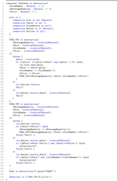
F. From Abstract to Executable Test Case
In this section, we explain how an abstract test case repre-sented by an IOSTS is translated into an executable code to be run on the black-box implementation of a system under test. First of all, the test case, shown in Fig.11 and called T CIOSTS, is
translated into the π-ADL-C&C component, shown on Fig.12 and called T Cπ-ADL-C&C, as follows:
a) The symbolic constants of T CIOSTS, such as
cCoinNumber, cBeverageQuantity, and cPrice, are transformed
1 componentTestCaseis abstraction( 2 cCoinNumber :Natural,// 10 3 cBeverageQuantity :Natural,// 15 4 cPrice :Natural)// 2 5 6 port is{
7 connectionCoinis out(Natural). 8 connectionCancelis out(). 9 connectionPressButtonis out(). 10 connectionReturnis in(Natural). 11 connectionDeliveris in(). 12 }.
13 ...
14 P2B3_TP2is abstraction(
15 vBeverageQuantity :location[Natural],
16 vPaid :location[Natural],
17 vCoinNumber :location[Natural],
18 vPrice :location[Natural]
19 ){ 20 choose{
21 pCoin :location(4).
22 if((cPrice’ <= pCoin’+vPaid’)and(pCoin’ > 0))then{
23 viaCoinsendpCoin.
24 vPaid := vPaid’+pCoin. 25 vCoinNumber := vCoinNumber’+1. 26 vPrice := cPrice’. 27 P2B4_TP3(vBeverageQuantity’,vPaid’,vCoinNumber’,vPrice’) 28 } 29 or
30 viaDeliverreceive.
31 Fail()
32 or
33 viaReturnreceivepPaid :location[Natural].
34 Fail()
35 }
36 }
37 P2B4_TP3is abstraction(
38 vBeverageQuantity :location[Natural],
39 vPaid :location[Natural],
40 vCoinNumber :location[Natural],
41 vPrice :location[Natural]
42 ){ 43 choose{
44 viaDeliverreceive.
45 if(vPaid’>=vPrice’)then{
46 vBeverageQuantity := vBeverageQuantity’+1.
47 P4B2_TP4(vBeverageQuantity’,vPaid’,vCoinNumber’,vPrice’)
48 }else{ Fail() }
49 or
50 viaReturnreceivepPaid :location[Natural].
51 if((pPaid’=vPaid’-vPrice’)and(vPaid’>=vPrice’))then{
52 Inconclusive()
53 }else{ Fail() }
54 or
55 viaReturnreceivepPaid :location[Natural].
56 if((pPaid’=vPaid’)and(vCoinNumber’>=cCoinNumber’))then{
57 Inconclusive()
58 }else{ Fail() }
59 }
60 ...
61 Passis abstraction(){ print("PASS") } 62 ...
63 behaviour is{ P1B1_TP1(0,0,0,0) } 64 }
Fig. 12. The extract of the π-ADL C&C test case.
b) The input/output actions of T CIOSTS (Deliver?,
Return?, and Coin!, Cancel!, PressButton!) play the role of
connectors in T Cπ-ADL-C&C(see lines 7-11).
c) Each location of T CIOSTS is transformed into an
abstraction of T Cπ-ADL-C&C. All the abstractions, except the
ones corresponding to the test verdicts, have the same number of parameters. These parameters correspond to the variables of T CIOSTS. For example, the location p2b3 tp2 of T CIOSTS
is translated into the abstraction P2B3 TP2 (see lines 14-36), which has four parameters: vBeverageQuantity, vPaid,
vCoinNumber, and vPrice. Notice that, the special locations,
such as Pass, Fail, and Inconclusive, correspond to the abstrac-tions without parameters (e.g., the location Pass corresponds to the abstraction represented by the code on line 61). The role of these abstractions is to produce a test verdict.
d) For each location of T CIOSTS, each outgoing
transi-tion is translated into one case of the “choose” structure of the abstraction corresponding to this location. For example, the transition t1with origin p2b3 tp2and destination p2b4 tp3
labeled with the Coin!(pCoin) output action corresponds to the first case of the “choose” structure of P2B3 TP2 (see lines 21-28). Notice that, the destination of t1 is modeled by a call
to the P2B4 TP3 abstraction. The code, corresponding to a guarded transition labeled with an output action, is surrounded by the “if(...)then{...}” structure, where the guard of this transition appears as a condition. Moreover, in order to fire a transition labeled with an output action carrying parameters, a test case should automatically generate values for these parameters satisfying the guard of this transition if it is present. At the moment, such parameters are instantiated with values chosen by the test developer. For example, the pCoin parameter is instantiated with 4. This value satisfies the guard of the transition t1, i.e., (pCoin > 0) and (cP rice ≤ pCoin + vP aid)
if the price of the beverage is 3, for example. The code, corre-sponding to a guarded transition labeled with an input action, is surrounded by the “if(...)then{...}else{...}” structure, where the guard of this transition appears as a condition. The input action should be invoked just before this structure as we need to know received values of its parameters. Notice that, if the guard/condition is not satisfied, then the test case generates the “Fail” verdict. For example, the code corresponding to lines 44-48, models two transitions of T CIOSTS outgoing from the
p2b4 tp3location and labeled with the Delivery?() action. One
of them permits to reach the p4b2 tp4 location, if the guard
g : vP aid ≥ pP rice is satisfied, and other goes to the “Fail” location, if the guard g is unsatisfied.
e) The behavior of the test case T Cπ-ADL-C&Cis modeled
by a call to the P1B1 TP1 abstraction, which corresponds to the initial location of T CIOSTS.
To obtain an executable test case, a test case expressed in the ADL-C&C language is automatically translated into π-ADL-Spec code (see Section IV-A), and then into a concrete executable test program expressed in the π-ADL.NET language (see Section IV-B).
G. Test Case Execution
The last step of our approach is to compile and to execute the π-ADL.NET test case obtained from an abstract test case, represented by IOSTS, as was explained in Section IV-F. This test case is executed on a real black-box implementation of the system under development, where the execution is modeled by the parallel composition between the test case and the implementation with synchronization on common input/output actions. The results of a test execution are: “Pass”, meaning no errors were detected and the test purpose was satisfied, “Inconclusive” – no errors were detected but the test purpose was not satisfied, or “Fail” – the implementation exhibits a non-conformance with respect to the architectural specification in a behavior targeted by the test purpose.
V. Tool Support
A major impetus behind developing formal languages for architectural description is that their formality renders them suitable to be manipulated by software tools. The usefulness of an ADL is thereby directly related to the kinds of tools it provides to support architectural description, but also analysis, refinement, code generation, and evolution. Indeed, we have developed a comprehensive toolset for supporting architecture-centric formal development around π-ADL. It is composed of:
– a callable compiler and a persistent virtual machine for ex-ecuting architecture descriptions based on the operational
semantics of π-ADL (implemented in C# on the .NET platform) [20];
– three transformators implemented in C++ and allowing to translate (1) a π-ADL-C&C code into a π-ADL-Spec code, (2) a π-ADL-Spec code into a π-ADL.NET code, and (3) a π-ADL-Spec code into an IOSTS model.
– a π-ADL-C&C syntax checker implemented in C++. The work presented in this paper adds a new method and tool for architecture validation based on conformance testing. Indeed, in order to validate the conformance of the executable system with respect to its architectural specification, we apply the conformance testing technique, i.e., tests are generated automatically, using the STG tool [17]–[19], and then they are executed on the system under test. To be able to generate tests from a π-ADL-Spec architectural specification with STG, the specification should be translated into a low-level IOSTS model. This step is almost automatized. The STG tool generates abstract test cases expressed by IOSTS, therefore we need also to transform them into the π-ADL-C&C language (this step is done manually, at the moment).
VI. Summary and Related Work
The main purpose of this paper is to propose an approach that permits (1) to easily design the architecture of a system under development using π-ADL, (2) to automatically generate an implementation of this system that can be executed on the platform .NET, and (3) to test the conformance of the implemented system against its architectural specification.
As it is mentioned in [2] and [3], several works propose different formal and semi-formal ADLs for the description of software architecture. Some of these ADLs rely on Labeled Transition Systems (LTSs) used to model the behaviors of a software architecture, for example, Chemical Abstract Machine (CHAM) [21], Finite State Process (FSP) [22], and π-ADL [4]. As this paper is based on our previous work [4], the choice of
π-ADL, as a language for architecture design, is natural for us. Once the architecture of a software system is designed using the user-friendly π-ADL-C&C language, we refine it into a low-level π-ADL.NET architecture that can be compiled, using the compiler [20] developed in our research team, and executed on the .NET platform.
The choice of π-ADL allows us to use formal methods in order to assure the quality of a system under development. Indeed, π-ADL is a formal, well theoretically founded ADL. Moreover, the behaviors of designed systems can be captured by means of transition systems. In this work, we use a testing technique in order to check the conformance of a system’s implementation with respect to its architectural specification, and therefore to assure the quality of this system. This work is based on our previously proposed technique [19] and on a tool [17], [18] allowing automatic test generation for reactive programs (written in Java or C++) from low-level specifications modeled by IOSTSs.
The closest works to our proposal are these of Muccini, Bertolino, and Inverardi [11], [12], [23], [24]. Their approach consists of the automatic derivation of suitable abstract test cases from the behaviors of a system under test that is modeled by LTS. The test cases are selected by the use of Abstract LTS (ALTS) allowing to abstract away uninteresting, for the
moment, system’s actions, and then applying the coverage criterion of McCabe (another criteria can also be used) to obtained abstract test cases. One of the difficulties of this approach underlined by the authors, is to establish a relation-ship between the system at its abstract architectural level and the system’s implementation. It is needed in order to obtain concrete executable test cases from the abstract ones.
In the approach presented in this paper, we generate ab-stract test cases from the IOSTS model of an architectural specification written in π-ADL. We use the notion of test pur-pose, as a test selection mechanism, in order to focus on specific behaviors of the system under test. The inconvenient is that we do not generate the test purposes automatically, therefore their elaboration needs a human intervention. On the other hand, the translation of abstract test cases is quite straightforward in our approach as it was described in Section IV.
Bellow we listed other related works that have been done in the domain of architectural testing. This list is certainly not exhaustive. The authors of [6] define six architectural-based testing criteria and use them in order to generate test plans from the software architecture modeled by CHAM by adapting existing specification-based techniques to the domain of architecture-based testing. In [7], Bertolino and Inverardi use the architectural testing in order to test extra-functional properties of a system under test. Tracz [25] shows how to use Domain-Specific Software Architecture (DSSA) in order to capture structural and temporal properties of a system under development. He gives some ideas on how architectures can be specified to enable its analysis and testing. In [8], [26], the au-thors propose dependence analysis techniques based on software architecture and called chaining. In [27], Rosenblum adapts its component-based test strategy based to an architecture-based test of software systems. This approach is architecture-based on the architectural models that can be simulated, executed, or used to realize the integration or regression testing on the implemen-tation of a system under test. Finally, the author describes how formal models, combined with architectural models, can be used to guide software testing. In [9], Harrold presents approaches for using software architecture for effective regression testing. In [28], she also discusses the use of software architecture for testing. In [10], the authors define several test criteria, and propose techniques, and automated tools for the specifi-cation and generation of system level tests from architectural descriptions. Muccini and his colleagues are also interested by regression testing. Their contribution to this topic can be found in [13], [29], [30]. These works explore the question how regression testing can be systematically applied to the software architecture to reduce the cost of regeneration tests for modified systems. The authors are interested in two types of changes of a software system, which are (1) modification of the architecture and (2) modification of the implementation. There is also an interesting work of Bertolino [31] discussing different important achievements in the field of software testing and listing the most relevant challenges to be addressed in this field.
VII. Conclusion
This paper has presented a formal approach which, starting from the architecture of a software system, generates a system implementation and tests it at the architectural level. In par-ticular, this approach has been applied to software systems
de-signed using high-level architecture description language called
π-ADL. The test part of the approach is based on symbolic test generation, which (1) automatically derives test cases in order to check the conformance of a system with respect to the behavior of an architectural specification selected by the test purposes; (2) automatically determines whether the results of the test execution are correct with respect to the architectural specification. It performs test derivation as a symbolic process, up to and including the generation of test program source code. The reason to use symbolic techniques instead of enumerative is that symbolic test generation allows us to produce (1) more general test cases with parameters and variables, which should be instantiated only before the test cases execution, and (2) test cases that are more readable by humans. We validated our approach on a simple example of the coffee machine.
As it was mentioned in this paper, some steps of our approach are semi-automatized, therefore, the first direction of our future work is to render the approach completely automatic from test generation down to test execution. To show the feasibility and utility of our approach we plan to apply it to a realistic case study. Second, we plan to work on the implemen-tation of a mechanism to automatically compute test purposes from the system architectural specification using, for example, coverage criteria instead of test purposes written by hand. Third, we plan to extend our approach by incorporating in it a technique of model checking in order to enable the automatic verification of critical parts of a system under development.
References
[1] S. Shaw and D. Garlan, Software Architecture: Perspectives on an Emerging Discipline. Prentice Hall, 1996.
[2] N. Medvidovic and R. N. Taylor, “A classification and compari-son framework for software architecture description languages,” IEEE Trans. on Software Eng., vol. 26, no. 1, pp. 70–93, 2000. [3] I. Malavolta, P. Lago, H. Muccini, P. Pelliccione, and A. Tang, “What industry needs from architectural languages: A survey,” IEEE Trans. Software Eng., vol. 39, no. 6, pp. 869–891, 2013. [4] F. Oquendo, “π-adl: an architecture description language based on the higher-order typed pi-calculus for specifying dynamic and mobile software architectures,” SIGSOFT Softw. Eng. Notes, vol. 29, no. 3, pp. 1–14, 2004.
[5] G. Myers, The Art of Software Testing. John Wiley & Sons, 1979.
[6] D. J. Richardson and A. L. Wolf, “Software testing at the architectural level,” in Proc. of ISAW and Viewpoints’96 on SIGSOFT’96 workshops, ser. ISAW’96. New York, NY, USA: ACM, 1996, pp. 68–71.
[7] A. Bertolino and P. Inverardi, “Architecture-based software testing,” in Proc. of ISAW-2 and Viewpoints’96 on SIGSOFT ’96 workshops, ser. ISAW’96. New York, NY, USA: ACM, 1996, pp. 62–64.
[8] J. A. Stafford, D. J. Richardson, and A. L. Wolf, “Chaining: A software architecture dependence analysis technique,” 1997. [9] M. J. Harrold, “Architecture-based regression testing of
evolv-ing systems,” in Proc. of the Int. Workshop on the Role of Soft-ware Architecture In Testing and Analysis, ser. ROSATEA’98, 1998, pp. 73–77.
[10] Z. Jin and J. Offutt, “Deriving tests from software architec-tures,” in Proc. of the IEEE Int. Symposium on Software Reliability Engineering, ser. ICSE’01, 2001, pp. 308–313. [11] A. Bertolino, P. Inverardi, and H. Muccini, “Formal methods
in testing software architectures,” in SFM, 2003, pp. 122–147.
[12] H. Muccini, A. Bertolino, and P. Inverardi, “Using software architecture for code testing,” IEEE Trans. on Software En-gineering, vol. 30, no. 3, pp. 160–171, March 2004.
[13] H. Muccini, M. S. Dias, and D. J. Richardson, “Reasoning about software architecture-based regression testing through a case study,” in Proc. of the Computer Software and Applications Conf., ser. COMPSAC’05, 2005, pp. 189–195.
[14] B. Beizer, Software Testing Techniques. New York: Van Nostrand Reinhold, 1990.
[15] G. J. Tretmans, “A formal approach to conformance testing,” Ph.D. dissertation, University of Twente, the Netherlands, De-cember 1992.
[16] D. Sangiorgi, “Expressing mobility in process algebras: First-order and higher-First-order paradigms,” Ph.D. dissertation, Univer-sity Edinburgh, UK, February 1992.
[17] D. Clarke, T. J´eron, V. Rusu, and E. Zinovieva, “STG: A Symbolic Test Generation tool,” in Proc. of the 8th Int. Conf. on Tools and Algorithms for the Construction and Analysis of System (TACAS’02), ser. LNCS, vol. 2280, Grenoble, France, April 2002, pp. 470–475.
[18] F. Ployette and F.-X. Ponscarme, “The STG tool page,” Available at http://www.irisa.fr/prive/ployette/stg-doc/stg-web.html, October 18, 2007.
[19] E. Zinovieva-Leroux, “Symbolic methods in test generation for reactive systems with data,” Ph.D. dissertation, University of Rennes 1, France, November 22, 2004.
[20] Z. Qayyum and F. Oquendo, “The π-adl.net project: an inclu-sive approach to adl compiler design,” WSEAS Transactions on Computers, vol. 7, no. 5, pp. 414–423, May 2008.
[21] P. Inverardi and A. L. Wolf, “Formal specification and analysis of software architectures using the chemical abstract machine model,” IEEE Trans. on Software Eng., vol. 21, no. 4, pp. 373– 386, 1995.
[22] J. Magee, J. Kramer, R. Chatley, S. Uchitel, and H. Fos-ter, “Ltsa - labelled transition system analyser,” Available at http://www.doc.ic.ac.uk/ltsa/, June 04, 2009.
[23] A. Bertolino, F. Corradini, P. Inverardi, and H. Muccini, “De-riving test plans from architectural descriptions,” in Proc. of the 22nd Int. Conf. on Software Engineering, ser. ICSE’00. New York, NY, USA: ACM, 2000, pp. 220–229.
[24] A. Bertolino, P. Inverardi, and H. Muccini, “An explorative journey from architectural tests definition downto code tets execution,” in Proc. of IEEE Int. Symposium on Software Reliability Engineering, ser. ICSE’01, 2001, pp. 211–220. [25] W. Tracz, “Test and analysis of software architectures,” in
Proc. of the 1996 ACM SIGSOFT Int. Symposium on Software Testing and Analysis, ser. ISSTA’96. New York, NY, USA: ACM, 1996, pp. 1–3.
[26] J. Stafford, D. Richardson, and A. Wolf, “Aladdin: A tool for architecture-level dependence analysis of software systems,” University of Colorado, Tech. Rep. CU-CS-858-98, 1998. [27] D. Rosenblum, “Challenges in exploiting architectural models
for software testing,” in Proc. of the Int. Workshop on the Role of Software Architecture in Testing and Analysis, ser. ROSATEA’98, Italy, Jul. 1998, pp. 49–53.
[28] M. J. Harrold, “Testing: a roadmap,” in Proc. of the Conf. on The Future of Software Engineering, ser. ICSE’00. New York, NY, USA: ACM, 2000, pp. 61–72.
[29] H. Muccini, M. Dias, and D.Richardson, “Towards software architecture-based regression testing,” in Workshop on Archi-tecting Dependable Systems (WADS), ser. ICSE’05, vol. 30:4. St. Louis, Missouri (USA): ACM, May 2005, pp. 1–7. [30] ——, “Towards software architecture-based regression testing,”
University of L’Aquila, Tech. Rep., 2005.
[31] A. Bertolino, “Software testing research: Achievements, chal-lenges, dreams,” in Proc. of the Future of Software Engineering, ser. ICSE’07. IEEE-CS Press, 2007, pp. 85–103.