Timing verification in Transaction Modeling
par
Alena Tsikhanovich
Département d’Informatique et de Recherche Opérationnelle Faculté des Arts et des Sciences
Thèse présentée à la Faculté des Arts et des Sciences en vue de l’obtention du grade de Philosophiae Doctor (Ph.D.) en Informatique
Décembre 2009
Cette thèse intitulée:
Timing verification in Transaction Modeling
Présentée par : Alena Tsikhanovich
a été évaluée par un jury composé des personnes suivantes :
Abdelhakim Hafid, président-rapporteur El Mostapha Aboulhamid, directeur de recherche
Guy Bois, co-directeur Jean-Pierre David, membre du jury
Smail Niar, examinateur externe
Résumé
Les systèmes Matériels/Logiciels deviennent indispensables dans tous les aspects de la vie quotidienne. La présence croissante de ces systèmes dans les différents produits et services incite à trouver des méthodes pour les développer efficacement. Mais une conception efficace de ces systèmes est limitée par plusieurs facteurs, certains d'entre eux sont: la complexité croissante des applications, une augmentation de la densité d'intégration, la nature hétérogène des produits et services, la diminution de temps d’accès au marché. Une modélisation transactionnelle (TLM) est considérée comme un paradigme prometteur permettant de gérer la complexité de conception et fournissant des moyens d’exploration et de validation d'alternatives de conception à des niveaux d’abstraction élevés.
Cette recherche propose une méthodologie d’expression de temps dans TLM basée sur une analyse de contraintes temporelles. Nous proposons d'utiliser une combinaison de deux paradigmes de développement pour accélérer la conception: le TLM d'une part et une méthodologie d’expression de temps entre différentes transactions d’autre part. Cette synergie nous permet de combiner dans un seul environnement des méthodes de simulation performantes et des méthodes analytiques formelles. Nous avons proposé un nouvel algorithme de vérification temporelle basé sur la procédure de linéarisation des contraintes de type min/max et une technique d'optimisation afin d'améliorer l'efficacité de l'algorithme. Nous avons complété la description mathématique de tous les types de contraintes présentées dans la littérature. Nous avons développé des méthodes d'exploration et raffinement de système de communication qui nous a permis d'utiliser les algorithmes de vérification temporelle à différents niveaux TLM.
Comme il existe plusieurs définitions du TLM, dans le cadre de notre recherche, nous avons défini une méthodologie de spécification et simulation pour des systèmes Matériel/Logiciel basée sur le paradigme de TLM. Dans cette méthodologie plusieurs concepts de modélisation peuvent être considérés séparément. Basée sur l'utilisation des technologies modernes de génie logiciel telles
que XML, XSLT, XSD, la programmation orientée objet et plusieurs autres fournies par l’environnement .Net, la méthodologie proposée présente une approche qui rend possible une réutilisation des modèles intermédiaires afin de faire face à la contrainte de temps d’accès au marché. Elle fournit une approche générale dans la modélisation du système qui sépare les différents aspects de conception tels que des modèles de calculs utilisés pour décrire le système à des niveaux d’abstraction multiples. En conséquence, dans le modèle du système nous pouvons clairement identifier la fonctionnalité du système sans les détails reliés aux plateformes de développement et ceci mènera à améliorer la "portabilité" du modèle d'application.
Mots-clés : Systèmes Matériels/Logiciels, vérification temporelle, analyse temporelle, modélisation transactionnelle, modélisation des systèmes à différents niveaux d'abstraction.
Abstract
Hardware/Software (Hw/Sw) systems are likely to become essential in all aspects of everyday life. The increasing penetration of Hw/Sw systems in products and services creates a necessity of their efficient development. However, the productive design of these systems is limited by several factors, some of them being the increasing complexity of applications, the increasing degree of integration, the heterogeneous nature of products and services as well as the shrinking of the time-to-market delay. Transaction Level Modeling (TLM) paradigm is considered as one of the most promising simulation paradigms to break down the design complexity by allowing the exploration and validation of design alternatives at high levels of abstraction.
This research proposes a timing expression methodology in TLM based on temporal constraints analysis. We propose to use a combination of two paradigms to accelerate the design process: TLM on one hand and a methodology to express timing between different transactions on the other hand. Using a timing specification model and underlining timing constraints verification algorithms can decrease the time needed for verification by simulation. Combining in one framework the simulation and analytical design exploration methods can improve the analytical power of design verification and validation. We have proposed a new timing verification algorithm based on the linearization procedure and an optimization technique to improve its efficiency. We have completed the mathematical representation of all constraint types discussed in the literature creating in this way a unified timing specification methodology that can be used in the expression of a wider class of applications than previously presented ones. We have developed the methods for communication structure exploration and refinement that permitted us to apply the timing verification algorithms in system exploration at different TLM levels.
As there are many definitions of TLM and many development environments proposing TLM in their design cycle with several pro and contra, in the context of
methodology which supports TLM in such a way that several modeling concepts can be seen separately. Relying on the use of modern software engineering technologies such as XML, XSLT, XSD, object oriented programming and others supported by the .Net Framework, an approach that makes an intermediate design model reuse possible in order to cope with time-to-market constraint is presented. The proposed TLM design methodology provides a general approach in system modeling that separates various application modeling aspects from system specification: computational models, used in application modeling, supported by the language used for the functional specification and provided by simulator. As a result, in the system model we can clearly identify system functionality without details related to the development platform thereby leading to a better “portability” of the application model.
Keywords: Hardware/Software system modeling, timing verification, temporal constraints analysis, transaction level modeling, multiple abstraction levels.
Table of contents
Résumé……… ... I Abstract………. ... III Table of contents ... V List of tables…. ... IX List of figures….. ... X List of figures.. ... X List of acronyms ... XIII Acknowledgments ... XV Chapter 1. Introduction ... 1 1.1 Motivation ... 1 1.1.1 Reuse ... 2 1.1.2 System specification ... 2 1.1.3 Design flow ... 31.1.4 Verification and validation techniques ... 4
1.2 Objectives and proposed approach ... 6
1.3 Contributions ... 8
1.4 Outline of the Thesis ... 9
Chapter 2. Existing design techniques ... 11
2.1 Main design flows ... 12
2.2 Specification/description languages ... 12
2.3 Models of computation ... 15
2.3.1 Communicating sequential processes [40] ... 16
2.3.2 Kahn process networks [8]. ... 17
2.3.5 Petri nets ... 18
2.3.6 Finite State Machine ... 18
2.4 Transaction Level Modeling (TLM) ... 19
2.4.1 SpecC definition ... 19
2.4.2 SystemC definition ... 21
2.4.3 Open Core Protocol – International Partnership TLM definition ... 26
2.4.4 TLM evolution ... 26
2.5 Discussion ... 28
Chapter 3. Software engineering technologies ... 31
3.1 XML technology [9] ... 31
3.2 XML processing ... 32
3.3 XSD technology [20] ... 33
3.4 .NET ... 34
3.5 Hw/Sw design and software engineering technologies and paradigms ... 35
3.5.1 Sesame framework [79] ... 35
3.5.2 Colif [79] ... 37
3.5.3 IP-XACT [82] ... 37
3.6 Discussion ... 39
Chapter 4. TLM Hw/Sw system specification and modeling methodology ... 40
4.1 Abstract model ... 41
4.2 XML Abstract model representation ... 42
4.3 Verification of the model structure ... 45
4.4 Simulation model generation ... 47
4.6 Experimentations ... 51
4.6.1 System Description ... 51
4.6.2 Abstract Model of audio-video server system ... 52
4.6.3 XML server system specification and CP server simulation model .. 53
4.7 Conclusion ... 55
Chapter 5. Timing specification in TLM ... 56
5.1 Expressing timing ... 56
5.2 Timing Analysis ... 61
5.2.1 Linear constraint systems ... 61
5.2.2 Max constraint systems ... 63
5.2.3 Max-Linear Systems ... 65
5.2.4 Min-Max Constraint Systems ... 69
5.2.5 Min-Max-Linear Constraint Systems ... 72
5.2.6 Assume-Commit Constraint Systems ... 72
5.2.7 Discussion ... 76
5.3 Min-max constraint linearization algorithm ... 77
5.3.1 Min-max constraint linearization ... 77
5.3.2 Algorithm Optimization ... 82
5.3.3 Experimentations ... 83
5.4 Timing in TLM ... 89
5.4.1 Timing modeling at CP+T level ... 90
5.4.2 Communication Exploration at PV and PV+T Levels ... 92
Chapter 6. Conclusions and future work ... 99
6.1 Conclusions ... 99
6.2 Future work ... 101
List of tables
Table I: Codesign methodologies ... 29
Table II: Decision matrix for selecting an XML processing approach [9] ... 33
Table III: Complexity of the maximum separation problem [25] ... 61
Table IV: Maximum separation time for the timing specification of Figure 30 ... 65
Table V: Timing separations for the Intel 8086 ROM read cycle ... 85
Table VI: Required and computed separations for the Intel 8086 ROM read cycle .. 86
List of figures
Figure 1: SLM to RTL gap [74] ... 5
Figure 2: Design process ... 11
Figure 3: Kahn process network ... 17
Figure 4: System modeling graph ... 20
Figure 5: TLM Abstraction Levels and Potential Flows [7] ... 22
Figure 6: CP level ... 23
Figure 7: CP+T level ... 23
Figure 8: PV, PV+T levels ... 24
Figure 9: TLM-2.0 approach [81] ... 28
Figure 10: IP-XACT specification [82] ... 38
Figure 11: CP Abstract Model ... 42
Figure 12: Graphic representation of the XML system specification ... 43
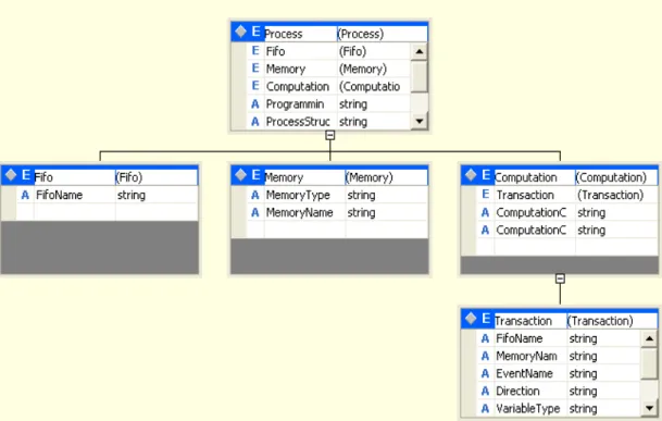
Figure 13: Graphic representation of the System Model node structure ... 44
Figure 14: Process node structure ... 44
Figure 15: XML tags for process description ... 45
Figure 16: Graphic representation of XML schema for process description ... 46
Figure 17: Fragment of process node transformation ... 47
Figure 18: Simulation model generation flow ... 48
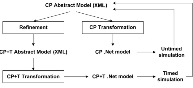
Figure 19: TLM level Transformation ... 48
Figure 20: Design flow ... 51
Figure 21: CP Abstract Models of Test Bench and Server System ... 52
Figure 23 : CP C# Transformation process ... 54
Figure 24 : C# code fragment after XSLT transformation ... 54
Figure 25: Read-cycle timing diagrams for the 8086 CPU [28] ... 57
Figure 26: Partial graphic representation of the timing diagram from Figure 25 ... 58
Figure 27: Interpretation of the different types of constraints [61] ... 59
Figure 28: Subgraph with linear constraints ... 60
Figure 29: Graphic representation of delay constraint ... 62
Figure 30: Max only constraint timing model ... 64
Figure 31: An event graph (a) and the corresponding compulsory graph (b) ... 66
Figure 32: An event graph and the corresponding slack graph in the first iteration .67 Figure 33: Reduction from 3-SAT to min/max problem ... 71
Figure 34: Event graph ... 74
Figure 35: Subgraphs used in the determination of local consistency property ... 75
Figure 36: Transformation of type 4 constraints into min-max-linear constraints ... 76
Figure 37: Min-Max linearization inequalities ... 77
Figure 38: Subgraph with the max constraints ... 78
Figure 39: Transformed max constraint ... 78
Figure 40: Transformed min constraint ... 79
Figure 41: Graph representation of the transformed max and min constraints ... 79
Figure 42: Initial graph with max constraints ... 81
Figure 43: Graph with transformed max constraints ... 82
Figure 44: Intel 8086 ROM read cycle ... 84
Figure 46: Structures of the generated graphs ... 87
Figure 47: Temporal model of the audio-video server system ... 91
Figure 48: Temporal specification of two communicating components ... 93
Figure 49: Solution for the temporal specification of Figure 48 ... 94
Figure 50: Changed temporal specification of Figure 48 ... 94
Figure 51: Events and signals involved in arbitration [28] ... 96
Figure 52: Timing specification of the bus arbitration ... 97
List of acronyms
ALG AlgorithmicALAP As Late As Possible
API Application Programming Interface
ASIC Application Specific Integrated Circuit
ASSP Application-Specific Standard Products
CA Cycle Accurate
CC Cycle Callable
CIL Common Intermediate Language
CLR Common Language Runtime
CNF Conjunctive Normal Form
CP Communicating Processes
CPU Central Processing Unit
CSP Communicating Sequential Processes
DOM Document Object Model
DT Discrete Time
DTD Document Type Definition
EDA Electronic Design Automation
EG Event Graph
FIFO First In First Out
FSM Finite State Machine
HDF Heterochronous DataFlow
HDL Hardware Description Language
Hw/Sw Hardware/Software
IP Intellectual Property
JIT Just-In-Time
LOTOS Language Of Temporal Ordering Specifications
OCP-IP Open Core Protocol – International Partnership
OSCI Open SystemC Initiative
PV Programmer’s View
ROM Read Only Memory
RTL Register Transfer Level
SAX Simple API for XML
SCE System on Chip Environment
SDF Synchronous DataFlow
SDL Specification and Description Language
SLM System Level Modeling
SOC System On Chip
SPIRIT Structure for Packaging, Integrating and Re-using IP within Tool-flows TLM Transaction Level Modeling
UM Use- Model
UML Unified Modeling Language
VHDL VHSIC Hardware Description Language
VHSIC Very High Speed Integrated Circuits
W3C World Wide Web Consortium
XML EXtensible Murkup Language
XSLT EXtensible Stylesheet Language Transformations XSD XML Schema Definition Language
Acknowledgments
I would like to express my gratitude to all those who gave me the possibility to complete this thesis. In particular, I would like to thank to my thesis adviser, Professor El Mostapha Aboulhamid. I will never be able to thank you enough for the great support during my studies. My special thanks I would like to address to my co-adviser, Professor Guy Bois, for his suggestions and knowledge. Finally, I’d also like to thank all peoples with whom I had chance to work.
Chapter 1.
Introduction
1.1 Motivation
Hardware/Software (Hw/Sw) systems are widely presented nowadays. Their impact on our life is very important as these systems are present in a variety of applications such as audio and video consumer products, communications, desktop and mobile computers, as well as professional areas like traffic control, environmental applications, driving and car control, medical systems, etc.
The increasing penetration of Hw/Sw systems in products and services creates a necessity of their efficient development. Several facts, which make the achievement of this goal quite complex, are:
– Increasing complexity of applications – Increasing degree of integration
– Heterogenic nature of products and services
– Wide diversity of non-functional constraints and applications – Shrinking time-to-market time
– Increasing importance of system flexibility [71].
According to Moore’s law, the complexity of integrated circuits in terms of the number of transistors on a chip will double every 18 month. This growth of complexity of micro-electronic components will correspondingly lead to exponential growth of the complexity of Hw/Sw systems. Furthermore, as the complexity of applications is increasing continuously and modern applications describe often the functionality of different nature, the complexity growth in the number of different technologies needed in building an Hw/Sw system is evident.
The facts mentioned above render the productive design difficult, leading to a necessity of resolving the following challenges in system design:
– Assuring the design of the right system on target, without over and without under specification
– Supporting in the design flow a passage from executable specification to implementation
– Providing improved verification and validation techniques as these tools remain a significant bottleneck in system modeling.
All system design challenges listed above presume several opportunities for actions detailed in the embedded systems roadmap [71] and the semiconductor design roadmap [72].
1.1.1 Reuse
Reuse is an important factor in making the development process efficient. The amount of reuse in different forms has to increase drastically. In the embedded systems roadmap [71] it is indicated that the amount of reuse of existing hardware, software and Hw/Sw components has to increase from 20% to at least 80%. In this direction it is necessary to promote, facilitate and develop the reuse of intellectual property (IP) blocks comprising both hardware and software components. For example, current embedded software methods and tools do not support reuse [71]. IP block descriptions have to be standardized in order to facilitate their exchange and integration in different design methodologies. Furthermore, the IP blocks regarding behavior, cost and performance have to be presented at different abstraction levels to achieve the highest degree of reusability.
1.1.2 System specification
The increasing internal and external complexity of systems as well as their diffusion into a multi-disciplinary world makes it very difficult to establish a specification that can serve as input, following a subsequent transformation, to a suitable implementation. The heterogeneity of designed systems will require that several technologies of implementation be combined on a carrier technology. Reusable parts and different kinds of metrics quantifying the design experience must
be developed to aid the designer in balancing constraints of different nature to obtain the final specification. In the specification domain, an urgent need exists for the development of methods that close the gap between requirements and specification, in particular in the expression of different kinds of constraints. Specifications and design representations need to be augmented with means to express properties which go beyond behavior and structure. The languages used in system modeling must make possible to express different time models and different constraint types such as real-time constraints, throughput, power dissipation and silicon area.
1.1.3 Design flow
The design flow of different methodologies can be divided into two parts: the first covers the flow from idea to some form of executable specification and the second covers the flow from executable specification to final implementation. The executable specification of the two parts of the design flow can be based on various models and can be presented at different levels of abstraction varying over a wide range and representing the system description with a different amount of details. This diversity of models and representations imposes an additional demand on the correctness of the design flow, on the capabilities of the design representations and on the correctness of the semantics of these representations, leading to the formalization of the entire design process. This in particular holds for the design flow from executable specification to the final implementation. The different steps in the design flow should be connected together in a more appropriate and less error prone manner. The development methods must put more emphasis on the formal semantics and models on which the design flow and the design representations are founded. Thus, developments in the area of design representations and design languages are needed.
Currently, no design languages or representations do exist that can be used throughout the design process. Moreover, at high levels of specification we need an integral representation of components of different nature, i.e. we need an appropriate representation of physics, mechanics, etc. together with behavior and structure. The design space exploration styles have to allow for requirement analysis in a mixed
technology framework by co-simulation of executable models of heterogeneous building blocks at the appropriate abstraction levels. It is necessary to develop methods and tools to explore design decisions concerning the allocation of computation and communication to resources with the possibility of early evaluation of the consequences of system requirements and obtaining high-quality solutions.
Another aspect of supporting a passage from specification to implementation is further automation of design tools. This trend imposes supplementary exigencies on compilers and translators used in the design. In this context a compiler is any translator that translates one representation into another and performs synthesis and optimization. The ultimate goal of the compiler is automatically map the behavior expressed by an executable specification on hardware. Thus, the compiler can determine both – underlying hardware and software. The derivation of hardware architecture from behavioral specification has to be based on several cost functions. Furthermore, for this hardware the dedicated software has to be generated too. The other kind of compilers urgently needed in Hw/Sw system design is a retarget compiler that efficiently delivers a code to execute on these designs. For these compilers a suitable representation of the target architecture is needed.
1.1.4 Verification and validation techniques
At each step of the design flow it is necessary to check whether the design implements the desired functionality. There are various techniques to do this; these can be separated into formal and non-formal groups. As modern designs are quite complex, there are very large state spaces associated with them. As such, current formal verification tools are not capable of examining these spaces in their entirety. Thus, a large part of verification is effectuated by simulation and emulation. The tendency of the design complexity to grow will maintain a need for simulation. However, as stated in the International Technology Roadmap for Semiconductors (ITRS) [72], the simulation does not scale as designs grow; simulation techniques can only cover a part of the design space. Therefore some new approaches have to be proposed to cope with the design verification issue. The shift from non-formal to formal verification techniques is considered as a breakthrough of the design
verification issue. The integration of formal verification and validation techniques with the design flow are the only ways to solve the growing simulation burden of verifying the correctness of the design steps. Although formal verification and validation are not feasible for all designs, they can be applied successfully in many cases. The analytical power of verification and validation tools has to be improved. Furthermore, much more attention has to be given to the correctness of the design tools. Verification and validation will be needed at low levels of abstraction as well as at higher levels. The relation with the top-level specification is very important to allow for integration of verification techniques in the system design flow. Electronic Design Automation (EDA) tools in general deal with the register transfer level (RTL) of abstraction and the abstraction levels below. At these levels EDA tools are very powerful, but as they demand very detailed system description they are very slow and are not suitable for validation of a whole complex system that could be further implemented in software or hardware. Thus, there is a gap between the system level modeling (SLM) and register transfer level (RTL) design (Figure 1) and a strong need for tools to bridge the system level to RTL gap in design and verification exists.
Analyzing the modern trends and tendencies in hardware and Hw/Sw system design we could summarize in the next paragraph the most promising solutions dealing with the above discussed problems. These solutions have been used in our research providing in this way new methods to cope with modern system design challenges.
1.2 Objectives and proposed approach
Raising the level of design abstraction, the need to increase the design productivity and reuse in all forms and at all levels are a must in designing increasingly complex systems. The necessity of a design methodology covering a passage from executable specification to implementation providing the system description and refinement at different abstraction levels, addressing the design productivity challenge, supporting reuse in different forms, providing sophisticated verification and validation techniques becomes evident. Several solutions aimed at efficient development were recently proposed.
The Transaction Level Modeling (TLM) paradigm supporting multiple higher than register transfer abstraction levels is one of these solutions. In TLM, the computation and communication components are modeled separately. Details of communication and computation are added gradually as necessary, thereby providing acceleration of simulation. The TLM allows the exploration and validation of design alternatives at higher levels of abstraction.
Software engineering technologies and paradigms are actively explored in the Hw/Sw design domain to augment design reuse. Several system level languages such as SystemC and SystemVerilog have some deficiencies that need to be eliminated. For example, these new languages cannot be used in system modeling by both hardware and software designers as they have some limitations in terms of visual descriptions and ease of use at the system level [74]. Some examples of work in this direction are:
– Using UML in conjunction with SystemC as a hardware requirement and description notation [76]-[78].
– Using XML technology for model descriptions [79], as storage format [79], or for description of meta-data for IP documenting [82].
Timing analysis and verification are important parts of system design. Accelerating these activities can drastically speed up the overall design process.
In this work we present a model of timing specification that can be used for acceleration of design space exploration in the Transaction Level Modeling design flow enhancing in this way the most promising simulation technique by analytical methods. The analytic timing specification representation is completely independent from description/modeling languages; this opens another possibility in terms of reuse. The analytical temporal model can be integrated in different design methodologies.
In the current design methodologies it is impossible to decouple the system model from the details imposed by the design framework. There are many aspects that influence the transformation of the initial specification into implementation thus making it non reusable in its intermediate forms by other design methodologies. The aspects, which are used in the design methodology to express the system model at different abstraction levels, are: design flow structure, choice of the specification language, computational models and paradigms. We propose a method permitting to achieve the orthogonalization of different modeling concepts providing in this manner better possibilities of reuse. The method is based on using the XML technology and the .NET Framework as a design environment for system specification.
The .NET Framework has been designed to ease application development in the highly distributed and heterogeneous environment of the Internet, something which assures powerful multi-paradigm support. In the software domain, the .NET Framework is becoming more and more a dominating design environment. These two facts make choosing the .NET Framework as a development platform very suitable and perhaps one of the best currently available solutions. Using .NET design
capabilities such as XML support, interoperability, .NET Framework class library, object-oriented programming, provides new possibilities in system exploration and eases and accelerates Hw/Sw system codesign.
1.3 Contributions
Our contributions in this work are:
– Proposition of a timing expression methodology in TLM flow. Currently, there is no methodology for timing specification representation in TLM. We propose to use a combination of two paradigms to accelerate the design process: TLM on one hand and a methodology to express timing between different transactions on the other hand. Using a timing specification model and underlying timing constraints verification algorithms can decrease the time needed for verification by simulation [65, 66].
– Proposition of methods for communication structure exploration and refinement in system design based on temporal constraints analysis. The proposed communication structure exploration methodology can be used in an automatic protocol generation, in determining temporal specification inconsistencies and in adjusting some parameters in the case of platform-based design methodologies [67]
– Presentation of a new algorithm with an optimization technique for timing verification of systems with deterministic and non-repetitive behavior handling all constraint types described in the literature and using the linearization of min-max inequalities [Erreur ! Source du renvoi introuvable.].
– Proposition of a specification/modeling methodology that supports transactional level modeling in the design cycle in order to handle the increasing complexity of systems; closing the gap between system and RTL
levels; speeding up the simulation process, providing in this manner a methodology that increases the design productivity[62].
– Development of a methodology where the specification is not committed to a hardware description language (HDL) nor to a specific programming language. This will allow reuse at different design stages, easier design exploration and exchange of specification between different users having different HDLs and implementation environments.
– Validation of the intermediate models’ structures at each abstraction level in order to assure correctness of the modeling. As correctness of design tools is a necessity in modern conditions, the possibility to guide the designer in the designing process through multiple abstraction levels respecting several modeling rules guarantees error reduction in system design.
– Combination of the transaction level modeling paradigm with software engineering technologies in order to provide an efficient method of separation of concerns. Using software engineering technologies in TLM expression eases the creation of high level transaction models and provides a method to productively explore some architectural concerns at a high level of abstraction [63].
1.4 Outline of the Thesis
The thesis is organized as follows: Chapter 2 presents an overview of existing design techniques underlining the diversity of different aspects differentiating them. It covers the existing design flow structure and the computation models used in specification languages and in application modeling. This review serves to demonstrate the enormous influence of the chosen methodology on intermediate representations of the modeling system. Particularly, attention is given to the presentation and evolution of the transaction level modeling paradigm.
Chapter 3 describes current software engineering technologies such as XML/XSLT and .Net paradigms that we use to achieve the separation of some environment related concerns from system representation. An overview of some
Hw/Sw design methodologies that use these software engineering technologies together with a discussion of the similarities and differences between them and the approaches that we have used are also presented in Chapter 3. The TLM Hw/Sw specification and simulation methodology is detailed in Chapter 4. At the beginning of this chapter, we present a description of the abstract model used for application modeling. Further, the XML abstract model representation is given followed by an explanation of methods assuring correct abstract model construction and simulation model generation. Finally, some experimentation results are given and discussed at the end of the chapter.
Chapter 5 covers a timing representation model. At the beginning, related work is presented and discussed. We analyze and summarize the descriptions of all constraint types and establish relationships between several of them. In addition, we present and discuss existing algorithms, introduce a new timing verification algorithm with an optimization technique and demonstrate experimental results. Finally, an application of the presented timing verification methodology in the TLM design flow is given and Chapter 6 concludes the thesis and gives directions for future work.
Chapter 2.
Existing design techniques
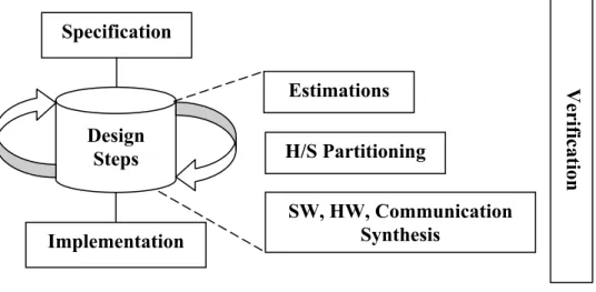
Design methodology is the key element in product development. Today’s systems are often too complex and require a strong methodology for successful product delivery. There exist a number of approaches in hardware and Hw/Sw system modeling. However, all design practices cover the design fully or partly, from system behavior to its detailed implementation, having the same goal: breakdown design complexity and produce better designs in shorter time (Figure 2).
Figure 2: Design process
Specification describes system behavior and non-functional system requirements such as: – time constraints – power/energy constraints – safety requirements – environmental aspects – cost, etc.
System specification can be formulated in natural language or using specification languages that make it more detailed and unambiguous. The intended behavior of the designed system can be presented as a relation between inputs and outputs or as an algorithm. Specification Implementation Design Steps Estimations H/S Partitioning SW, HW, Communication Synthesis Verification
In today’s design methodologies it is impossible to decouple the system model from the details imposed by the design framework. There are many aspects that influence the transformation of the initial specification into implementation making it non reusable in its intermediate forms by other design methodologies. These aspects are: design flow structure, choice of the specification language for modeling, computational models and paradigms used in the design methodology to express system model at different abstraction levels.
2.1 Main design flows
There are three general strategies in system modeling based on the design flow structure: top-down, bottom-up and meet-in-the middle.
Top-down strategies, such as that proposed by the System-On-Chip Environment (SCE) [1] start the design flow from system behavior description representing the design’s functionality and refine it by adding implementation details until the system gradually reaches the implementation model. In general, system architecture is generated from behavior in these kinds of methodologies.
Bottom-up approaches, such as those used in [5], deal with the existing computation components, which are assembled by means of inserting wrappers among them. Bottom-up strategies focus on component reuse and wrapper generation.
Meet- in-the middle approaches [2] and [3] are a combination of both bottom-up and top-down strategies. In systems developed using the meet-in-the middle approach, system architecture is predefined but the system behavior has to be explored and refined to meet architecture constraints.
2.2 Specification/description languages
The choice of a suitable language for system specification is very important for the design methodology. Generally a trade-off between several criteria such as the expressiveness of the language, the automation capabilities provided by the model
underlying the language as well as the availability of methods and tools supporting the language [34] must be made. Specification/description languages describe the desired functionality of a system in a way that captures system characteristics. The semantics of each language are defined by the underlying model of computation [14]. This model defines the expressiveness of the language, i.e. what kind of systems can be described with the language. Languages with high expressiveness can specify numerous systems with different characteristics. However, they also make formal reasoning and automated synthesis extremely complex and in some cases impossible [14]. Below, we will consider some specification languages used in hardware and Hw/Sw modeling. They can be categorized as follows:
– Programming Languages or system level design languages (SpecC, SystemC, etc.)
o The SpecC language [20] is defined as an extension of the ANSI-C programming language with the goal of supporting specification and design of digital embedded systems, including hardware and software parts. The SpecC language features concepts essential for embedded system design such as behavioral and structural hierarchies, concurrency, communication, synchronization, state transitions and timing.
o SystemC [18] is a C++ class library and a simulation kernel that allows the creation of cycle-accurate models and system-level designs. The SystemC class library provides the constructs needed to express hardware timing, concurrency, and reactive behavior that are missing in standard C++.
– Hardware Description Languages (VHDL, Verilog, etc.)
o VHDL (VHSIC Hardware Description Language) [42] and Verilog [43] are the standard description languages for digital systems. They support very well system description at low levels of abstraction (RTL). System representation at high levels of description is possible but complex and is not widely used by the designers.
– Languages specialized for specification of systems in particular areas and displaying unique features:
o Formal Description Techniques (LOTOS, SDL, etc.)
LOTOS [35] (Language of Temporal Ordering Specifications) is a language that is very suitable in describing concurrency, communication and data structures; however, the concept of time is missing. It is based on Process Algebra. The properties of Process Algebra are used in order to prove correctness of specifications. The language is widely used in protocol and distributed systems specifications.
SDL [36] (Specification and Description Language) is a general purpose description language for communicating systems. It is based on the model of extended finite state machines and can be used to model real-time, stimulus-response systems.
o Real Time System Languages (Esterel, Statecharts)
Esterel [48] is a programming language dedicated to programming reactive systems, including real-time systems and control automata. This language provides powerful concepts for expressing time, though the communication model is restricted to the specification of synchronous systems [44].
StateCharts [45] is a language that has been developed in order to deal with problems of specification and design of large reactive systems. The basis for the StateChart language is the Hybrid state machine proposed by David Harel. StateCharts is used to depict the behavioral view of a system, which is described by means of hierarchical states with corresponding transitions. Moreover, these transitions are triggered by
conditions and events. The communication model used in StateCharts is broadcasting whereas the execution model is synchronous.
o Parallel Programming Languages (CSP, Occam)
CSP (Communicating Sequential Processes language) [46] is Process Algebra designed for the description and analysis of concurrent systems. CSP is based on formal mathematics thereby allowing the designer to specify requirements unambiguously and to satisfyingly prove their implementation. In the next section, we will consider some of the models of computation commonly used to describe hardware and Hw/Sw systems that have been employed in the above presented specification languages.
2.3 Models of computation
A model of computation in the general sense can be defined as a set of theoretical choices that adequately express some problem. We can distinguish a computational model or models underlying the specification language from computational models that can be constructed on the top of the language.
Any design can be viewed abstractly as a set of components interacting with each other and with their environment. In this context, the model of computation describes the behavior and interaction methods of these components. The aspects that models of computation usually refer to are:
internal semantics of component functionality related to it computation communication
relationships in terms of concurrency
Concurrency is one of the aspects that differentiates computational models. The concurrency can be
Control-driven.
In data-driven concurrency the ordering of executions is not explicitly specified. Parallelism is determined by data dependencies. In control-driven concurrency explicit constructs are used to specify parallel and sequential execution.
Various communication and synchronization mechanisms are used in the different computation models: shared memory, message-passing communications, blocking and non-blocking communications control-depending and data-depending synchronizations. The last very important component of each computation model is a time representation [14].
A variety of models have been proposed for concurrent systems. We will consider some computation models commonly used to describe hardware and Hw/Sw systems:
Communicating sequential processes (CSP) Kahn Process Network
Dataflow models Discrete Event Petri nets
Finite State Machine
2.3.1 Communicating sequential processes [40]
In the CSP computation model, the components are sequential processes that run concurrently and communicate using the synchronous message passing technique. Synchronous communication in CSP means the presence of a mechanism that ensures that, in case of data transfer, the receiver process is in an adequate state to accept the information. The notion of time is absent. Time consuming actions have to be modeled using a pair of events (an event is an atomic action with zero duration). This model of computation is very appropriate to represent applications dealing with resource management problems.
2.3.2 Kahn process networks [8].
In this model, concurrent processes (Figure 3) communicate through unidirectional channels with unbounded capacity using a first-in-first-out (FIFO) policy. A read operation is blocking, i.e. an attempt to read from an empty channel will lead to a process stall. A write operation is non-blocking. Processes perform sequential computation and, at any given time, they may be in two states: a computing state or a waiting for information on one of its input lines state.
Figure 3: Kahn process network
2.3.3 Dataflow models
SDF – Synchronous Dataflow [49]. In the SDF model, components execute some actions according to a predetermined schedule, i.e. the modeled system is presented as a directed graph where the nodes describe computations and the arcs data paths. Any node performs its computation (fires) when the input data is available on incoming arcs. When the node fires, several tokens will be consumed or produced on each arc. In the SDF model, the number of tokens on each arc is specified a priori. Communication is strictly controlled and there is no notion of time. This model is very appropriate for representing digital signal processing applications.
HDF – Heterochronous Dataflow. This is a heterogeneous composition of the SDF and the finite state machine models. The HDF computation model
Kahn Process Channel
Kahn Process Kahn Process
allows rate changes through state transitions of the FSM, while within each state the system can be considered as an SDF model.
DT – Discrete Time. This model is an SDF model with the added notion of time. Furthermore, it has a global time and period.
2.3.4 Discrete Event
In discrete event models [50] system components communicate according to the events that are ordered on a global timeline. An event is an instantaneous action which causes a transition from one discrete state to another. The communication between computational tasks (processes) is implemented by means of signals that represent a set of atomic events occurring in some instant of physical time. Thus, each event is associated with a value and a timestamp [47]. Each action can be the event generator or event receiver. This computation model is widely used in digital logic to simulate behavior of digital systems (VHDL, Verilog simulators).
2.3.5 Petri nets
Proposed by C.A. Petri in1966, the Petri nets computation model consists of three elements: the S-elements (places), T-elements (transitions) and tokens. Places and transitions are related to each other by a flow relation. Two important characteristics of Petri nets are concurrency and the asynchronous nature of this model. The asynchronous property signifies that there is no inherent clock mechanism for firing transitions. Petri nets are very useful to represent the control structures of digital systems.
2.3.6 Finite State Machine
The FSM model consists of a set of sequential states linked by transitions. An operation of the system is strictly ordered by a set of corresponding transitions. As the classical FSM representations do not allow concurrency of states, a number of extensions and variations have been suggested:
– Codesign FSM [51].
2.4 Transaction Level Modeling (TLM)
The TLM modeling approach has been widely discussed in system-level design community as an approach to handle the complexity of system-on-chip and time-to-market pressures [6, 7, 21, 22, 23]. There are many definitions of TLM and many development environments proposing TLM in their design cycle. In this section, we will consider some TLM definitions, the evolution of this modeling paradigm and why it became the first choice for many researchers.
Most definitions denote transaction level models as models where the communication and computation of systems are considered separately. This definition has a vague meaning and there are many types of models that fit this description.
2.4.1 SpecC definition
The TLM definition proposed by L. Cai and D. Gajski [6] is closely connected to the SpecC modeling principles. We have mentioned the SpecC modeling language in subsection 2.2.
TLM in SpecC interpretation defines several transaction level models, each of which is adopted for a different design purpose. These TLM models are:
Component-assembly model Bus-arbitration model Bus-functional model
Cycle-accurate computation model.
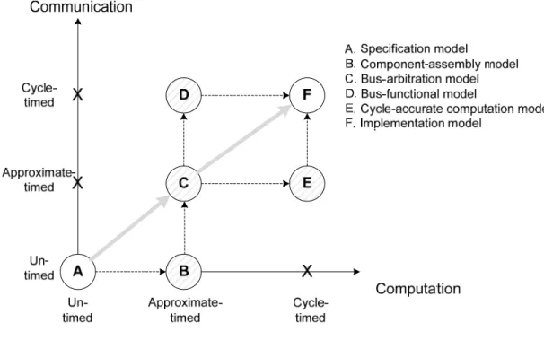
The TLM models serve to simplify the design process by slicing the entire design into several smaller design stages. Each design stage has a specific design objective. At each of these design stages, the corresponding models can be simulated and estimated independently. The system modeling graph shown in Figure 4 relates different models. On the graph, the axes represent computation and communication
with a time accuracy of three degrees: untimed, approximate-timed and cycle-timed. The untimed degree signifies computation/communication descriptions without any notion of time and represents the description of only pure functionality. The approximate-timed degree presumes that system level implementation details are added to system descriptions. The models with this degree of time accuracy contain information about the selected system architecture and the specification process mapping to the processing elements of the system architecture. The cycle-timed computation/communication models contain implementation details at system and RTL levels. In the system modeling graph shown in Figure 4, the TLM abstraction models (B, C, D, and E) are shown together with two others, namely the specification and implementation models. This is done to demonstrate the relationships between all models used in design.
Figure 4: System modeling graph
The specification model is untimed and can describe system functionality without implementation details. The component-assembly model describes concurrently executing processing elements which communicate through channels.
The communication part of the model is untimed while the computation part of the model is timed. The estimated time of computation is computed by a system level estimator. The component-assembly model explicitly specifies the allocated processing elements in the system architecture and the mapping decision of processes to processing elements. In the bus-arbitration model, some bus protocol details are added with approximate timing to the channel message passing mechanism. The bus-functional model contains cycle accurate communication and approximate-timed computation descriptions. Two types of bus-functional models exist: time-accurate and cycle accurate. Time-accurate models specify timing constraints of communication; cycle-accurate models specify the time in terms of the bus master’s clock cycles. In the cycle-accurate computation model, the computation is accurate, i.e. computation components are pin accurate and function cycle-accurately whereas communication is approximate-timed. Finally, the implementation model represents cycle accurate communication and computation. The processing elements are defined in terms of their register-transfer or instruction set architecture.
In Figure 4 a common design flow is indicated by the gray solid arrow going through the specification and bus-arbitration models and finishing with the implementation model. The specification model represents system functionality, the bus arbitration model denotes abstract system architecture and the implementation model deals with cycle-accurate system implementation. The bus-arbitration model (C) divides the system flow in two stages: system design and component design. In the first stage, the system architecture is selected or generated and the system behavior is mapped to that architecture. In the second stage of the design flow, the computation and communication components are refined to a cycle accurate level and possibly synthesized. Different design flows containing different models exist.
2.4.2 SystemC definition
Below, we will consider the SystemC (section 2.2) definition of TLM proposed by A. Donlin [7]. According to [7], TLM refers to a set of abstraction levels each differing from one another in the degree of expression of functional or temporal
details. These levels, and the possible design flows through the TLM space, are presented in Figure 5 together with an indication of their situation between the algorithmic (ALG) and register transfer levels (RTL) that are not considered to be a part of TLM space. Transaction-modeling levels are:
Communicating Processes (CP)
Communicating Processes with Time (CP+T) Programmer’s View (PV)
Programmer’s View with Time (PV+T) Cycle Accurate (CA)
Figure 5: TLM Abstraction Levels and Potential Flows [7]
The Communicating Processes level is characterized by the representation of system behavior as a network of parallel processes that exchange complex, high-level data structures. Processes communicate using point-to-point links. Systems described at this level are generally architecture and implementation independent. However, the separation of functionality into parallel tasks imposes some architectural concerns. The main activity at this abstraction level is functional
Application
Simulate Analyse & Verify
Figure 6: CP level
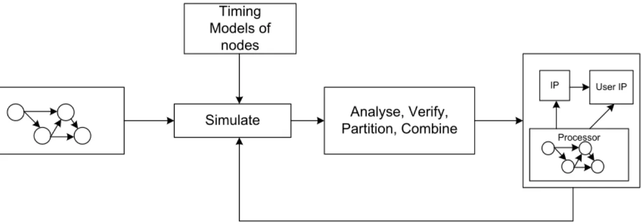
At the Communicating Processes with Time level, some timing information has to be added. Nodes may contain quite accurate or high-level estimates of timing data. Communication timing models are abstract and the exact communication protocol is not defined. The main design activity is design space exploration (Figure 7).
Figure 7: CP+T level
The Programmer’s View level defines a transport mechanism between model components with some elements of arbitration. The hardware sub-system at this level may be seen as an accurate programmer’s representation by low-level software drivers.
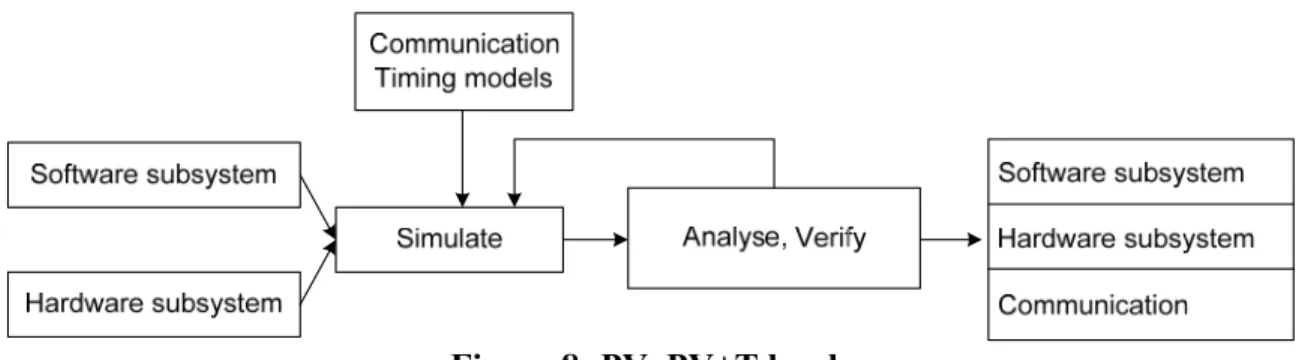
The Programmer’s View with Time level is functionally identical to the PV level model with the exception of timing information. The timing model is much more precise. The abstract communication structure is transformed to a given interconnection type and soft-real-time functional verification is enabled (Figure 8).
Simulate Partition, CombineAnalyse, Verify, Timing
Models of nodes
IP User IP
Figure 8: PV, PV+T levels
The Cycle Accurate model contains micro-architectural details. It has all timing annotations and is accurate to the level of individual clock cycles.
According to the features and requirements of particular product-types the author [7] distinguishes five TLM use-models which are suitable for different application domains. Each use model will respect a design flow which is a subset of levels and paths given in the Figure 5:
– Use-Model 1 (UM1) is a model of ASSP-based (Application-Specific Standard Products) systems. The basic characteristic of such systems is their pre-ordained architecture. A designer has to implement an application on a given platform, i.e. in software destined to execute on the ASSP. As UM1 is characterized by its software dominated nature, CP and CP+T levels are not applied. PV and PV+T levels support hardware platform parameter tuning and functional verification. The CA level enables detailed performance analysis of the application using elaborate platform parameter tuning.
– Use-Model 2 (UM2) describes systems based on structured ASIC (Library-oriented micro-architecture design). In these systems, a hardware subsystem is a result of an incremental refinement of an existing reference architecture specification. Customization of the subsystem specification in these models is limited by the next type of variations:
o IP module replacements
o Addition of some small number pieces to IP o Alternation of the IP provision subset.
In UM2, the CP level captures the application behavior description in an architecture agnostic manner. The CP+T level is not used. The PV level enables software development and functional verification whereas PV+T and CA support the same activities as in UM1.
– Use-Model 3 (UM3) is a model from the Structured ASICs domain with a much greater degree of hardware subsystem customization than UM2. This allows satisfying design performance goals, functional goals or both. In this model, the designer works with a reference hardware architecture and with the ability to add custom-designed IP to the interconnection architecture of the system. In this model, CP, PV, PV+T and CA levels support almost the same activities as in UM2. The increasing degree of customization in UM3 introduces some design space exploration presented at the CP+T level by means of high level performance estimation and partitioning of application functionality.
– Use-Model 4 (UM4) is based on custom designed ASIC. In this model, there is no initial architecture template; some vendor supplied component models are still present. Comparing with UM3, much more application functionality is partitioned into the hardware domain with the aim of realizing it as a custom logic. The design activity in UM4 is equivalent to that in UM3. There is one difference, however, in the shifting of emphasis from PV, PV+T to CP and CP+T levels.
– Finally, Use-Model 5 (UM5) presents a model that allows customization of all system aspects to achieve maximum performance and functionality. In this model design space exploration plays an extremely important role. All abstraction levels are presented in UM5, but the most significant work is concentrated in the CP and CP+T levels.
2.4.3 Open Core Protocol – International Partnership TLM definition
The Open Core Protocol – International Partnership (OCP-IP) TLM defines a set of layers of abstraction that together create a link between architecture exploration and System on chip (SoC) implementation. These layers are: Message Layer (L-3), Transaction Layer (L-2) and Transfer Layer (L-1) [58].
The Message Layer or Layer 3 is the highest level of abstraction which can be used by SoC architects to prove concept tools, to rationalize first order functional partitioning and to explore some system level architectural concerns. This layer is also one of executable specifications. L-3 models are untimed and event driven.
The transaction Layer or Layer 2 serves to make detailed hardware performance analysis and hardware/software partitioning. At this level, low level drivers can be interfaced with hardware simulation models and Operating System simulators can be integrated with hardware emulators. L-2 models are structurally accurate enough to allow modeling a complete system. An event-driven computational model contains approximate timing and is highly parametrical. Computation models at the L-2 level are independent of any bus fabric protocols.
The transfer Layer or Layer 1 is used by designers to perform detailed tasks such as modeling the interfaces of embedded processors, creating cycle accurate test benches and carrying out cycle accurate performance simulations. L-1 models are clocked cycle-accurate.
2.4.4 TLM evolution
We have only presented some TLM definitions from the myriad available. As we can see, the necessity of standards in TLM was urgent [59] in order to provide a possibility for model exchange within companies and across IP producers. Some attempt has been done early trying to link the Open SystemC Initiative (OSCI) and OCP-IP TLM world [58]. Furthermore, the initial SystemC definition [7] has been revised and OSCI TLM levels have become [58]:
– Programmer’s View with Timing (PV+T) – Cycle Callable (CC).
TLM abstracts away the number of events and the amount of information that has to be processed during simulation of the minimum required. In SystemC, the TLM definition of the necessary information is presented to the designer as a TLM API (Application Program Interface). The OSCI TLM API represents a set of interfaces that define how models communicate. At PV level, an interface does not contain communication events, carries little timing information and is implemented as a function call. At PV+T level, the simulation can switch between two interfaces with and without timing. This level is characterized by allowing model refinement without changing the functional description of the model’s behavior. The CC level provides a cycle accurate modeling style. The interface explicitly describes the cycle-by-cycle behavior. As the behavior of the model is coupled with the interface, it includes cycle timing. The CC level uses higher level ports rather than pin-accurate signals while still remaining at TLM abstraction.
Recently, a new transaction level modeling standard, TLM-2.0, was announced by OSCI [19]. Standard transaction level modeling approaches aim to enable model interoperability and exchange within companies and between companies. The new standard includes some changes. Models have been categorized according several characteristics such as granularity of time, frequency of model evaluation, functional abstraction, communication abstraction and use cases. The existence of a variety of use cases for transaction level modeling is explicitly recognized and TLM-2.0 uses an approach of distinguishing between APIs on one hand and coding styles on the other rather than defining an abstraction level around each use case as shown in Figure 9. The TLM-2.0 standard defines a set of interfaces and describes a number of coding styles for various use cases. The interfaces are low-level programming mechanisms for implementing transaction level models and form the normative part of the standard thereby ensuring interoperability. A coding style is defined as “a set of programming language idioms that work well together, not a specific abstraction
level or software programming interface” [81]. Each coding style supports a range of abstraction functionality, communication and timing.
Use cases Software development Software performance Architectural analysis Hardware verification
TLM-2 Coding styles Each style supports a range of abstractions Loosely-timed
Approximately-timed
Mechanisms
Blocking
interface DMI Quantum Sockets
Generic payload Non-blocking interface Phases Figure 9: TLM-2.0 approach [81]
In our work, we have chosen the SystemC terminology for TLM as the SystemC modeling language was in its standardization process. Now, the SystemC standardization process has finished with several changes introduced in the new SystemC TLM definition. In our work, we referred to the terminology initially proposed in [7].
2.5 Discussion
There are many of codesign methodologies that use different computational models in system modeling in order to simplify the design process of complex systems [13, 14, 17, 18, 19]. All modeling elements add to the system description a multitude of details which are relevant to the particular environment thus allowing the intermediate system representations to be tightly coupled with the design environment. In Table I, we summarize different design methodology aspects which
influence the transformation process of specification into implementation for some codesign methodologies (the presented list is not exhaustive).
Table I: Codesign methodologies Codesign
Environment Application Specification language Model Vulcan [52] Data oriented HardwareC DFG Set
Cosyma Data oriented Cx Syntactic tree
Ptolemy [18] Real Time Silage CDFG
Polis [17] Control-dominated systems Esterel CFSM :Codesign Finite State Machines Cosmos Control-dominated systems SDL SOLAR: communicating extended FSM CoWare [4],
SPACE [85] Various SystemC Discrete TLM Event,
SPADE [57] Signal processing applications
C Kahn process
networks SpecSyn [54] Different SpecCharts Hierarchical
program state machine (PSM) Tosca [53] Control-dominated
systems OCCAM CSP
Chinook [55] Control-dominated
systems Verilog Modal processes
All these methodologies use one specification/description language in their design cycle. Different computation models provided by some of these design methodologies are constructed on the top of specification/description language related to the methodology. Utilization of a restricted computation model has the advantage that a system might be modeled in an unambiguous way and formal verification techniques might be applied. A disadvantage consists of a restriction of the represented application class. For the methodologies that support quite general computation models, verification by simulation is the only viable solution to test the model correctness. Formal verification techniques may be used to verify only a part of the design. In all cases, the process transforming a specification into
implementation is highly related to the methodology. There exists a multitude of methodologies, such as CoWare [4] for example, that support reuse at the component or module level. It should be noted, however, that we are talking about a finer level of reuse here, which is that of functional descriptions used inside a module or component for different design methodologies. These intermediate representations of a system under design are impossible or difficult to reuse as the computation model and the specification/description language choice influence the model description enormously.
Chapter 3.
Software engineering technologies
The application of software engineering methodologies to hardware and Hw/Sw design is an active field of research within the hardware design community. In our research, we have used modern software engineering technologies such as XML, XSLT and other software engineering paradigms in order to represent the system model at different abstraction levels with a clear separation from the design’s environment details. This approach leads to better model reuse and “portability”.
3.1 XML technology [9]
Extensible Markup Language, XML [9], – is a markup language designed to provide a standard way to describe content.
Markup languages are characterized by:
– Description of the text structure within the document. – Separation of content from formatting.
Generalized Markup Languages are HTML (Hypertext Markup Language), SGML (Standard Generalized Murkup Language) and XML.
HTML, contrary to SGML and XML, is technically a markup language that in reality is used as a formatting language. In HTML, content and representation are defined together within the same document.
SGML is a very powerful markup language that is widely used to handle complex, large documents across platforms. SGML’s complexity and a limited set of elements for structuring documents in HTML format created the need for XML creation.
XML is a subset of SGML. It provides many of SGML’s complex features but in a more manageable form. XML uses element tags to mark up content according to a set of rules created by the document’s developer called the Document Type Definition (DTD).
XML provides the ability to
– define the new elements and attributes,
– nest document structures within other document structures, – check the validity of document structure.
With XML, the layout is separate from the content. The mechanism of style sheets is used to drive the layout in order to display the content across different applications. XSL, Extensible Stylecheet Language, is a language that implements the style sheets mechanism for XML. XSL consists of two parts: one is composed of some formatting features and the other of XSLT. XSLT (XSL transformations) describes syntax for transforming a document from XML format to another. In the next subsection, we will give a more detailed description of the role of XSLT in XML treatment.
3.2 XML processing
Like many formatting languages, XML requires parsers and processors in order to adequately convert the incorporated content. Parsers currently used for XML usually take the form of a code library written in programming languages. The parser verifies the syntax of the DTD and XML document and then the processor provides access to the content and structure of the document.
There are three different approaches to accessing an XML document in a program:
– The Document Object Model (DOM),
– The Simple Application Programming Interface (API) for XML (SAX), – The Extensible Stylesheet Language Transformations (XSLT) approach. In the DOM approach, the entire XML document is placed in memory as a hierarchical “tree” and the programmer has the possibility to apply various methods to locate and manipulate the nodes of the tree.
![Figure 1: SLM to RTL gap [74]](https://thumb-eu.123doks.com/thumbv2/123doknet/12502554.340406/22.918.249.749.626.970/figure-slm-to-rtl-gap.webp)
![Figure 5: TLM Abstraction Levels and Potential Flows [7]](https://thumb-eu.123doks.com/thumbv2/123doknet/12502554.340406/39.918.371.629.412.808/figure-tlm-abstraction-levels-potential-flows.webp)
![Figure 9: TLM-2.0 approach [81]](https://thumb-eu.123doks.com/thumbv2/123doknet/12502554.340406/45.918.195.808.172.577/figure-tlm-approach.webp)
![Table II: Decision matrix for selecting an XML processing approach [9]](https://thumb-eu.123doks.com/thumbv2/123doknet/12502554.340406/50.918.191.818.674.869/table-ii-decision-matrix-selecting-xml-processing-approach.webp)