HAL Id: hal-00689785
https://hal.inria.fr/hal-00689785
Submitted on 20 Apr 2012
HAL is a multi-disciplinary open access
archive for the deposit and dissemination of
sci-entific research documents, whether they are
pub-lished or not. The documents may come from
L’archive ouverte pluridisciplinaire HAL, est
destinée au dépôt et à la diffusion de documents
scientifiques de niveau recherche, publiés ou non,
émanant des établissements d’enseignement et de
for a Decentralized Composite Service Execution
Héctor Fernandez, Cédric Tedeschi, Thierry Priol
To cite this version:
Héctor Fernandez, Cédric Tedeschi, Thierry Priol. A Chemistry-Inspired Workflow Management
Sys-tem for a Decentralized Composite Service Execution. [Research Report] RR-7924, INRIA. 2012,
pp.23. �hal-00689785�
ISRN INRIA/RR--7924--FR+ENG
RESEARCH
REPORT
N° 7924
Workflow Management
System for a
Decentralized Composite
Service Execution
RESEARCH CENTRE
RENNES – BRETAGNE ATLANTIQUE
Execution
Héctor Fernández, Cédric Tedeschi, Thierry Priol
Project-Teams Myriads
Research Report n° 7924 — April 2012 — 23 pages Abstract:
With the recent widespread adoption of service-oriented architecture, the dynamic composition of such services is now a crucial issue in the area of distributed computing. The coordination and execution of composite Web services are today typically conducted by heavyweight centralized workflow engines, leading to an increasing probability of processing and communication bottleneck and failures. In addition, centralization induces higher deployment costs, such as the computing infrastructure to support the workflow engine, which is not affordable for a large number of small businesses and end-users. Last but not least, central workflow engines leads to diverse inadequate consequences dealing with privacy or energy consumption.
In a world where platforms are more and more dynamic and elastic as promised by cloud computing, decentralized and dynamic interaction schemes are required. Addressing the characteristics of such platforms, nature-inspired analogies recently regained attention to provide autonomous service coordination on top of dynamic large scale platforms.
In this report, we propose a decentralized approach for the execution of composite Web services based on an unconventional programming paradigm that relies on the chemical metaphor. It pro-vides a high-level execution model that allows executing composite services in a fully decentralized manner. Composed of services communicating through a persistent shared space containing con-trol and data flows between services, our architecture allows to distribute the composition among nodes without the need for any centralized coordination. A proof of concept is given, through the deployment of a software prototype implementing these concepts, showing the viability of an autonomic vision of service composition.
Key-words: Service composition, Decentralization, Workflow execution, Nature-inspired models,
Résumé :
Suite à l’adoption grandissante des architectures orientées service, la composition dynamique de services est devenu un problème important de la construction de plates-formes de calcul distribué.
La coordination et l’exécutiuon de Web Service composites sont aujourd’hui typiquement conduits par des moteurs de workflows (graphes de composition de services, formant un service
composite ) centralisés, entrainant différents problèmes, et notamment une probabilité
grandis-sante d’apparition d’échecs ou de goulots d’étranglement.
Dans un monde où les plate-formes sont de plus en plus dynamiques (ou élastiques, comme envisagé par les clouds, de nouveaux mécanismes de coordination dynamiques sont requis. Dans ce contexte, des métaphores naturelles ont gagné une attention particulière récemment, car elles fournissent des abstractions pour la coordination autonome d’entités (commes les services.)
Dans ce rapport, une approche décentralisée pour l’exécution de Web Services composites fondée sur la métaphore chimique, qui fournit un modèle d’exécution haut-niveau pour l’exécution décentralisée, est présentée. Dans cette architecture, les services communiquent à travers un espace virtuellement partagé persistant contenant l’information sur les flux de contrôle et de données, permettant une coordination décentralisée des services. Un prototype logiciel a été développé et expérimenté. Les résultats de ces expériences sont présentés à la fin de ce rapport.
Mots-clés : Composition de services, Décentralisation, Exécution de workflows, Modèle inspiré
Contents
1 Introduction 3
2 The Chemical Paradigm 4
3 Chemical Decentralized Workflow Execution 6
3.1 Architecture . . . 6
3.2 Chemical Workflow Representation . . . 8
3.3 Generic Rules for Invocation and Transfer . . . 10
4 Execution Example 11 5 Software Prototype 14 5.1 Global Design . . . 14 5.2 Communications . . . 15 6 Experimental Results 15 6.1 Workflows Considered . . . 16
6.2 Managing Large Workflows . . . 17
6.3 Exchanging Data . . . 18 6.4 Workflow’s Complexity . . . 19 6.5 Discussion . . . 19 7 Related Works 20 8 Conclusion 21
1
Introduction
Loose coupling and dynamic composition are building block requirements of service oriented ar-chitectures (SOA) [21], and also two of the keys to their success. Building on these concepts, the Internet of services is now a global computing platform gathering myriads of autonomous het-erogeneous services such as storage space, computing power, or more often software components offered to the users through the web.
SOA is now a multipurpose paradigm, facilitating business processes as well as helping sci-entific investigations based on computer-intensive applications. In both fields, the combinations of services allow to build more complex applications known as composite web services which are a temporal composition of services usually represented by a workflow, describing data and control dependencies between services. Recently, and in spite of the decentralized nature of the Internet, service infrastructures have built upon highly centralized architectures. Data centers and Cloud computers act today as servers centralizing the storage and processing required for the coordination of services and, more generally, of clients (users or businesses) of the Internet. Such architectures lead to various weaknesses. First, they generally suffer from poor scalability and low reliability, servers being potential processing and communication bottlenecks as well as single points of failure [1]. Also, they raise privacy issues, all data and control passing through central servers and repositories.
It becomes crucial to promote a decentralized vision of service infrastructures, as for instance suggested in [26]. The benefits of a decentralized approach are manifold. First, as the processing and data are distributed among a set of nodes, there is no single point of failure. No central
server acts as a potential bottleneck, network traffic is reduced, and the approach is globally more scalable. Second, the direct and asynchronous fashion of communications (without the need for central coordination) brings better throughput and graceful degradation [9]. Finally, no server takes control over data and work, each node integrating a local workflow engine (referred to as local-engine in the following), and having only a partial view of the composition.
More specifically, the execution of a composite Web service relies on an engine responsible for coordinating data and control flows between involved services. For the sake of illustration, let us consider a simple workflow W consisting of an activity A performed at node a followed by activity B performed at node b. In a centralized vision, during the actual execution of W , the engine first invokes A by sending a message to node a, then waits for the result of A (sent by a), and finally invokes B. With a decentralized workflow engine, nodes a and b may communicate directly (rather than through a central coordinator node) to transfer data and control when necessary (e.g., after A finishes).
Recently, nature-inspired metaphors have been shown to be of high interest for service co-ordination [24]. The chemical programming paradigm is a high-level execution model. Within such a model, a computation is seen as a set of reactions consuming some molecules floating and interacting freely within a chemical solution (close to the biological notion of membrane) and producing new ones. Reactions take place in an implicitly parallel, autonomous, and de-centralized manner. This particular model has been shown to naturally expresses distributed coordination [4]. The Higher-Order Chemical Language (HOCL) [2] is a language based on these concepts and providing the higher-order: every entity in the system is seen as molecules; rules can apply to other reaction rules, opening doors to self-adaptation, the program being able to modify itself. It has been recently shown that such a paradigm is well-suited to express service orchestration [4], and describe the enactment of workflows [17]. The proper investigation of this paper is to show that the chemical model is well-featured for underlying a decentralized execution of composite Web services and give a proof of such a concept. In particular, in the approach presented, both data and control flows of the workflow are distributed.
The remainder of this paper is organized as follows. Section 2 presents the chemical pro-gramming paradigm in more details. Section 3 details our decentralized coordination model and language. Section 4 illustrates the work by an example of coordination of a more complex workflow. Section 5 focus on the prototype software of the decentralized workflow engine thus designed. Section 6 details the experimental campaign and its results. Section 7 presents similar works. Section 8 draws some conclusions.
2
The Chemical Paradigm
The chemical paradigm is a programming style based on the chemical metaphor. Molecules (data) are floating in a chemical solution, and react according to reaction rules (program) to produce new molecules (resulting data). Reactions are conditional, and take place between some molecules satisfying a reaction condition. This process continues until no more reactions can be performed: the solution is said to be inert. Reactions take place in an implicitly parallel and autonomous way, and in a non-deterministic order.
Formally, the solution is represented by a multiset containing molecules, and rewriting/trans-formation rules specify the reactions between molecules. The Gamma model (General Abstract Model for Multiset Manipulation) [3] has been a pioneer work realizing the chemical paradigm. The multiset, which is the formal representation of the chemical solution, is the unique data structure in Gamma. The multiset works similarly to a shared address space on which multiple processors can operate independently.
In this paper, we use a chemical language enhanced with higher order, called HOCL (Higher
Order Chemical Language) [2]. In HOCL, every entity is a molecule, including reaction rules. A
program is a solution of molecules, that is to say, a multiset of atoms (A1, . . . ,An) which can
be constants (integers, booleans, etc.), sub-solutions (denoted hMii), or reaction rules.
Following the chemical paradigm, the execution of an HOCL program consists in applying reactions until the solution becomes inert. A reaction involves a reaction rule one P by M if
V and a molecule N that satisfies the pattern P and the reaction condition V . The reaction
consumes the rule and the molecule N, and produces M. The basic one P by M C reaction rule is one-shot: it disappears when it reacts. Its variant replace P by M C is n-shots: it is not consumed when it reacts. In the following, we use a more advanced syntax to declare and name
molecules: let x = M1in M2 is equivalent to M2where all occurrences of x are replaced by M1.
For instance, consider the following solution MaxNumbers which calculates the maximum value of a given set of numbers. The below example illustrates the expressiveness and higher order of HOCL, where reactions consume and/or produce other reaction rules.
let max = replace x, y by x if x ≥ y in h2, 3, 5, 8, 9, maxi
The rule max reacts with two integers x and y such that x ≥ y and replaces them by x (keep the integer with highest value). Initially, several reactions are possible: max can react with any couples of integers satisfying the condition: 2 and 3, 2 and 5, 8 and 9, etc. In order for the final solution to contain only the result, we introduce a higher-order rule responsible to delete the max rule once the solution only contain the highest integer value. This introduces the need for sequentiality of events: we need to wait that all possible reactions between max and couples of integers took place before deleting the rule. Within the chemical model, the sequentiality is achieved through sub-solutions: to access a sub-solution, a rule has to wait for its inertia. In our example, this leads to the encapsulation of the solution:
hh2, 3, 5, 8, 9, maxi, one hmax = m, ωi by ωi
The m variable matches a rule named max, and ω matches all the remaining elements. One possible execution scenario within the sub-solution is the following (2 and 8, as well as 3 and 5, react first, producing the intermediate state):
h2, 3, 5, 8, 9, maxi →∗h3, 5, 9, maxi →∗h9, maxi
Once the inertia is reached within the sub-solution, the one-shot rule can be triggered, ex-tracting the result:
hh9, maxi, one hmax = m, ωi by ωi → h9i
As we illustrated with a fine-grain example, HOCL provides the ability to express autonomic coordination of rules (without the need for any centralized control). The current state of a computation is represented by the solution, that constitutes an information system by itself. In other words, the multiset is a shared space providing the information required for dynamic coordination, such as a decentralized workflow execution.
3
Chemical Decentralized Workflow Execution
In this section, we describe our decentralized architecture for workflow coordination based on a higher-order chemical framework, illustrating the adequacy of the chemical paradigm to execute composite Web services.
3.1
Architecture
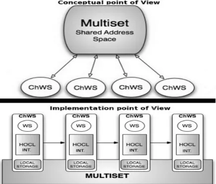
As illustrated by Figure 1, the proposed architecture is composed by two core elements, namely the Chemical Web Service (ChWS) and a Multiset. A ChWS is a chemical encapsulation of a Web service. It is co-responsible with other ChWSes of the coordination of the execution of workflows. Physically, ChWSes are hosted by some nodes and logically identified by symbolic names into this multiset. Each ChWS is basically equipped with three elements, namely:
Each ChWS is equipped with a chemical engine and a local copy of part of the multiset on which its chemical interpreter will act, to realize its part of the coordination. The multiset, containing the workflow definition and thus all required coordination information, will now act as a space shared by all ChWSes involved in the workflow. In other words, ChWSes will communicate by reading and writing it, as illustrated by Figure 1.
1. The service caller represents the encapsulation of a Web service invocation. The invocation to the effective possibly distant Web service, is encapsulated in a chemical expression readable by a chemical interpreter. The implementation of the Web service itself is not encapsulated, as shown in Figure 1.
2. A local storage space containing part of the multiset, i.e., molecules and reaction rules constituting the data and control dependencies related to the coordination of workflow execution.
3. An HOCL interpreter, working as the chemical local-engine executing the reactions ac-cording to molecules and reaction rules stored in the multiset, responsible for applying the defined workflow patterns and transferring data and control information to other ChWSes involved in a workflow.
ChWSes, containing all information needed by ChWSes for a decentralized execution of a workflow, and in which each ChWS can operate independently. This information combines molecules representing data and ChWSes, rules representing control dependencies of the work-flow, and rules for the coordination of its execution, as illustrated by Figure 2. Data and control dependencies of the workflow are defined beforehand using some workflow executable languages, like the well-known BPEL [23], an XML-based workflow language for Web services. The BPEL specification is translated into a chemical program, as detailed in Section 3.2. To coordinate the execution of the workflow, we also need some additional chemical rules, which are generic, i.e., independent of a specific workflow. Section 3.3 focuses on these generic rules.
Figure 1: The proposed architecture.
The multiset shares some conceptual similarities with the Distributed Shared Memory (DSM) paradigm [20], developed in the area of distributed operating systems. DSM maps a globally unique logical memory address to a local physical memory slot, thus emulating a shared global space on top of a distributed memory platform. By analogy, multiset mirrors DSM’s behavior by exposing molecules and reactions rules physically scattered across a set of ChWSes in a single shared space.
In other words, from a conceptual point of view (illustrated by Figure 1), ChWSes com-municate through a unique global multiset containing all information needed by ChWSes to execute their part of a workflow. ChWSes exchange data and control dependencies through this multiset. In a classical centralized workflow architecture, the services themselves do not know these dependencies, as an engine manages all information and executes coordinates the whole execution.
Figure 2: Chemical workflow.
From an implementation point of view, the multiset is physically distributed. While ap-parently, each ChWS only interacts with the multiset, physically, data and control information
(molecules and reaction rules of the multiset) are effectively transferred between local storages of ChWSes. Put together, the molecules stored by ChWS form the multiset. Figure 3 summarizes these two points of view: the upper side shows the conceptual point of view where all ChWSes are connected through one multiset; the lower part shows the implementation point of view where all ChWSes are directly interconnected through the multiset, the reactions and molecules being directly transferred from one ChWS to another one using a distributed multiset as detailed in [19]. Figure 3 provides a simple example where all ChWS are connected through a sequential workflow (modeled by arrows), but any workflow pattern could be applied, similarly.
Figure 3: Different points of view of the architecture.
3.2
Chemical Workflow Representation
In order to express all data and control dependencies of a workflow definition according to the chemical paradigm and to distribute the information among ChWSes, we use a series of chemical abstractions inspired by the work in [17]. These abstractions allow representing a workflow definition with the HOCL language. Such a representation is given in Algorithm 1.
As a chemical expression, the whole solution represents the multiset containing all informa-tion. The solution itself is composed of as many sub-solutions as ChWSes. Each sub-solution represents a ChWS with its data and control dependencies with other ChWSes within the work-flow definition. More formally, a ChWS is one molecule of the form ChW Si : h. . . i where ChWSi refers to the symbolic name given to the service whose connection details and physical position are hidden, as shown in Algorithm 1.
Algorithm 1General chemical workflow representation 1.01 h // Multiset (Solution) 1.02 ChWSi:h. . . i // ChWS (Sub-solution) 1.03 ChWSi+1:h. . . i 1.04 . . . 1.05 ChWSn:h...i 1.06 i
Let us consider a simple workflow composed of the four services shown on Figure 4. It is
composed of four services S1, S2, S3and S4. In this example, after S1completes, S2 and S3 can
be invoked in parallel. Once S2and S3 have both completed, S4can be invoked.
Figure 4: Simple workflow example.
The corresponding chemical representation for this workflow is presented in Figure 5. As we already mentioned, the solution contains as many sub-solutions as Web services. ChW S1 :
h. . . i to ChW S4 : h. . . i represent ChWSes in the solution. The relations between ChWSes
are expressed through molecules of the form Dest:ChWSi with ChW Si being the destination ChWS where some information needs to be transferred. For instance, we can see in ChW S1 sub-solution that ChWS1 will transfer some information (the outcome of ChWS1) to ChWS2 and ChWS3 (Line 2.02).
2.01 h // Multiset (Solution)
2.02 ChWS1:hDest:ChWS2, Dest:ChWS3i, // (Sub-solution)
2.03 ChWS2:hDest:ChWS4, replace Result:ChWS1:value1 by Call:S2, Param:h(value1)i i,
2.04 ChWS3:hDest:ChWS4, replace Result:ChWS1:value1 by Call:S3, Param:h(value1)i i,
2.05 ChWS4:hreplace Result:ChWS2:value2, Result:ChWS3:value3 by Call:S4, Param:h(value2)i
2.06 i
Figure 5: Chemical workflow representation.
Let us focus on the details of these dependencies. ChWS2 has a data dependency: it requires
a molecule Result:ChWS1:value1 containing the result of S1 to be invoked (second part of
input parameters. They are expressed using a molecule of the form Call:Si, and a molecule
Param:hin1,...,inn i, where in1,...,inn represent the input parameters to call the service Si. In
Figure 5, this input parameter corresponds to the result of some previous service Sj. ChWS3
works similarly.
Occasionally, on a particular service, data and control dependencies may differ. Consider ChWS4. As specified by Figure 4, ChWS4 needs to wait until ChWS2 and ChWS3 have been completed. This constitutes a control dependency known as synchronization. However, as we
can see in line 2.05, the service S4 is invoked only on value2 which is the result of S2. This
constitutes a data dependency. The ChW S4 sub-solution contains one reaction rule translat-ing those dependencies in chemical language (see line 2.05): the presence of molecules Re-sult:ChWS2:value2 and Result:ChWS3:value3 inside the ChW S4 sub-solution expresses the fulfillment of the control dependencies, to start its own execution. In addition, a data dependency
is also expressed in ChWS4: the result of S2is required to call S4. During the execution, as soon
as Result:ChWS2:value2 and Result:ChWS3:value3 appear in the ChW S4 sub-solution, the local engine of ChWS4 will be able to perform the reaction that will produce two new molecules
of the form Call:S4 and Param:h (value2) i to call the effective service S4on the input value2.
To sum up, one reaction rule can express both control and data dependencies. In contrast with the previous synchronization pattern, the simple data dependencies are enough to express
the simple parallel split pattern of S1 with S2 and S3. Thanks to the implicit parallelism of
the chemical execution model, the reaction rules inside ChW S2 and ChW S3 can be executed
in parallel. Therefore, ChWS2 and ChWS3 will receive the result of S1 from ChWS1 and the
invocation of S2 and S3 will take place in parallel.
This fragment of HOCL code is the chemical representation of a workflow, that will be interpreted by chemical local engines, performing the decentralized execution of this workflow thanks to a set of generic rules we introduce in the next sections.
3.3
Generic Rules for Invocation and Transfer
As previously mentioned, to ensure the execution of a chemical workflow, additional chemical
generic rules (i.e., independent of any workflow) must be defined. These rules are included in
the chemical local engines and are responsible for the efficient execution of the workflow. We now review three of these generic rules, illustrated in Algorithm 2, responsible for these tasks, and that will be commonly encountered in the compositions presented later. The invokeServ rule encapsulates the actual invocation of services. When reacting, it invokes the Web Service
Si, by consuming the tuples Call:Si representing the invocation itself, and Param:hin1,...,inn
i representing its input parameters, and generates the molecules containing the results of the
invocation in the ChWSi sub-solution. The molecule Flag_Invoke is a flag whose presence in the solution indicates that the invocation can take place. The preparePass rule is used for preparing the messages to transfer the results to their destination services, that will later trigger the execution of the passInfo rule. Thus, the preparePass rule captures one molecule of the form ChWSi:hResult:ChWSi:hvaluei, Dest:ChWSj, ω i. Result:ChWSi:hvaluei is the result
of Si, while Dest:ChWSj comes from the chemical specification of the workflow such as the one
presented in Figure 5.
Rule passInfo transfers molecules of information between ChWSes. This rule reacts with
a molecule ChWSi:hPass:d:hω1 ii that indicates that some molecules (here denoted ω1) from
ChWSi needs to be transfer to d. These molecules, once inside the sub-solution of d will trigger
the next step of the execution. Therefore, the molecule ω1 will be transferred from sub-solution
ChWSi to sub-solution ChWSj, when reacting with passInfo rule.
Algorithm 2Basic generic rules.
3.01 let invokeServ = replace ChWSi:hCall:Si, Param:hin1, . . . , inni, Flag_Invoke, ω i, 3.02 by ChWSi:hResult:ChWSi:hvaluei, ω i
3.03 let preparePass = replace ChWSi:hResult:ChWSi:hvaluei, Dest:ChWSj, ωi
3.04 by ChWSi:hPass:ChWSj:hCompleted:ChWSi:hvaluei i, ωi
3.05 let passInfo = replace ChWSi:hPass:ChWSj:h ω1i, ω2i, ChWSj:h ω3i 3.06 by ChWSi:h ω2i, ChWSj:h ω1, ω3i
each ChWS is able to execute rules using its embedded HOCL interpreter, each ChWS achieving the coordination related to the service it encapsulates.
4
Execution Example
To better understand how the coordination between chemical engines works, we here present a workflow example, illustrated in Figure 5, for which we focus on each step of the coordination logic. These steps are listed in Figures 6 (steps 1-3), 7 (steps 4-7) and 8 (steps 8-10). Recall that, thanks to the higher-order property, reaction rules react themselves with other molecules. An example composed by four ChWSes applying parallel split and synchronization patterns is illustrated in Figure 4. The execution is as follows: After ChWS1 completes, it forwards the result to ChWS2 and ChWS3 in parallel. Once ChWS2 and ChWS3 have completed, ChWS4 can start. Consider that each chemical local engine is responsible for the reactions taking place within its sub-solution in the multiset, thus respecting at runtime the decentralization designed. Indeed, for the sake of clarity, we only mention the molecules that take part in the logic of the coordination.
The first step (Lines 4.02-4.08) corresponds to the initial state of the multiset, illustrated in Figure 6. Initially, the only possible reaction is inside ChWS1, the invokeServ rule is triggered by the HOCL interpreter of ChWS1, producing the outcome molecule Result:ChWS1:hvali. This
molecule represents the result of the invocation of S1. Then, the preparePass rule consumes the
molecules Dest:destination and Result:ChWS1:hvali, preparing the parallel split. Therefore, it produces two new molecules for the distribution of this result to ChWS2 and ChWS3 (Lines 4.29-4.30). Finally, still through ChWS1, passInfo triggers it by transferring in parallel the outcome of ChWS1.
4.01 h
4.02 ChWS1:hDest:ChWS2,Dest:ChWS3, invokeServ, preparePass, passInfo, Call:S1, Param:in1i, 4.03 ChWS2:hDest:ChWS4, invokeServ, preparePass, passInfo,
4.04 replace Completed:ChWS1:hvali by Call:S2, Param:(val)i,
4.05 ChWS3:hDest:ChWS4, invokeServ, preparePass, passInfo,
4.06 replace Completed:ChWS1:hvali by Call:S3 Param:(val)i,
4.07 ChWS4:hinvokeServ,
4.08 replace Completed:ChWS2:hval2i, Completed:ChWS3:hval3i by Call:S4, Param:(val2)i
4.09 i
↓
4.10 h
4.11 ChWS1:hDest:ChWS2,Dest:ChWS3, preparePass, passInfo, invokeServ, Call:S1, Param:in1 i,
4.12 ChWS2:hDest:ChWS4, invokeServ, preparePass, passInfo,
4.13 replace Completed:ChWS1:hvali by Call:S2, Param:(val)i,
4.14 ChWS3:hDest:ChWS4, invokeServ, preparePass, passInfo,
4.15 replace Completed:ChWS1:hvali by Call:S3 Param:(val)i,
4.16 ChWS4:hinvokeServ,
4.17 replace Completed:ChWS2:hval2i, Completed:ChWS3:hval3i by Call:S4, Param:(val2)i
4.18 i
↓
4.19 h
4.20 ChWS1:hDest:ChWS2,Dest:ChWS3, preparePass, passInfo, Result:ChWS1:hvalii,
4.21 ChWS2:hDest:ChWS4, invokeServ, preparePass, passInfo,
4.22 replace Completed:ChWS1:hvali by Call:S2, Param:(val)i,
4.23 ChWS3:hDest:ChWS4, invokeServ, preparePass, passInfo,
4.24 replace Completed:ChWS1:hvali by Call:S3 Param:(val)i,
4.25 ChWS4:hinvokeServ,
4.26 replace Completed:ChWS2:hval2i, Completed:ChWS3:hval3i by Call:S4, Param:(val2)i
4.27 i
↓
4.28 h
4.29 ChWS1:hpassInfo, Pass:ChWS2:hCompleted:ChWS1:hvali i, Result:ChWS1:hvali, 4.30 Pass:ChWS3:hCompleted:ChWS1:hvali i i,
4.31 ChWS2:hDest:ChWS4, invokeServ, preparePass, passInfo,
4.32 replace Completed:ChWS1:hvali by Call:S2, Param:(val)i,
4.33 ChWS3:hDest:ChWS4, invokeServ, preparePass, passInfo,
4.34 replace Completed:ChWS1:hvali by Call:S3 Param:(val)i,
4.35 ChWS4:hinvokeServ,
4.36 replace Completed:ChWS2:hval2i, Completed:ChWS3:hval3i by Call:S4, Param:(val2)i
4.37 i
Figure 6: Workflow execution, steps 1-3.
Once the information is received by ChWS2 and ChWS3, the reactions (Lines 5.04 and 5.06)
are triggered, in parallel, producing the needed molecules to invoke S2 and S3. Thus, molecules
of the form Call:Si and Param:(val) contained into ChWS2 and ChWS3 respectively, launch
the invokeServ rule (Lines 5.03-5.05) that generates the result of S2and S3. Similarly to ChWS1,
Finally, in ChWS2 and ChWS3, the passInfo rule propagates the molecule Pass:ChWS4:h
infor-mation ito ChWS4 (Lines 5.26-5.27).
5.01 h
5.02 ChWS1:hResult:ChWS1:hvali i,
5.03 ChWS2:hDest:ChWS4, invokeServ, preparePass, passInfo, Completed:ChWS1:hvali,
5.04 replace Completed:ChWS1:hvali by Call:S2, Param:(val)i,
5.05 ChWS3:hDest:ChWS4, invokeServ, preparePass, passInfo, Completed:ChWS1:hvali,
5.06 replace Completed:ChWS1:hvali by Call:S3, Param:(val)i,
5.07 ChWS4:hinvokeServ,
5.08 replace Completed:ChWS2:hval2i, Completed:ChWS3:hval3i by Call:S4, Param:(val2)i
5.09 i
↓
5.10 h
5.11 ChWS1:hResult:ChWS1:hvali i,
5.12 ChWS2:hDest:ChWS4, invokeServ, preparePass, passInfo, Call:S2, Param:(val)i,
5.13 ChWS3:hDest:ChWS4, invokeServ, preparePass, passInfo, Call:S3, Param:(val)i,
5.14 ChWS4:hinvokeServ,
5.15 replace Completed:ChWS2:hval2i, Completed:ChWS3:hval3i by Call:S4, Param:(val2)i
5.16 i
↓
5.17 h
5.18 ChWS1:hResult:ChWS1:hvali i,
5.19 ChWS2:hDest:ChWS4, Result:ChWS2:hval2i, preparePass, passInfoi,
5.20 ChWS3:hDest:ChWS4, Result:ChWS3:hval3i, preparePass, passInfoi,
5.21 ChWS4:hinvokeServ,
5.22 replace Completed:ChWS2:hval2i, Completed:ChWS3:hval3i by Call:S4, Param:(val2)i
5.23 i
↓
5.24 h
5.25 ChWS1:hResult:ChWS1:hvali i,
5.26 ChWS2:hPass:ChWS4:hCompleted:ChWS2:hval2i i, passInfo, Result:ChWS2:hval2i i,
5.27 ChWS3:hPass:ChWS4:hCompleted:ChWS3:hval3i i, passInfo, Result:ChWS3:hval3i i,
5.28 ChWS4:hinvokeServ,
5.29 replace Completed:ChWS2:hval2i, Completed:ChWS3:hval3i by Call:S4, Param:(val2)i
5.30 i
Figure 7: Workflow execution, steps 4-7.
The execution ends with steps in Figure 8, processed by ChWS4’s local engine. Once the information from ChWS2 and ChWS3 is received by ChWS4, the reaction rule (Line 6.06) can
react with results molecules to produce two new molecules for invoking service S4 (Line 6.12).
6.01 h
6.02 ChWS1:hResult:ChWS1:hvali i, 6.03 ChWS2:hResult:ChWS2:hval2i i,
6.04 ChWS3:hResult:ChWS3:hval3i i,
6.05 ChWS4:hinvokeServ, Completed:ChWS2:hval2i, Completed:ChWS3:hval3i,
6.06 replace Completed:ChWS2:hval2i, Completed:ChWS3:hval3i by Call:S4, Param:(val2)i
6.07 i ↓ 6.08 h 6.09 ChWS1:hResult:ChWS1:hvali i, 6.10 ChWS2:hResult:ChWS2:hval2i i, 6.11 ChWS3:hResult:ChWS3:hval3i i,
6.12 ChWS4:hinvokeServ, Call:S4, Param:(val2)i
6.13 i ↓ 6.14 h 6.15 ChWS1:hResult:ChWS1:hvali i, 6.16 ChWS2:hResult:ChWS2:hval2i i, 6.17 ChWS3:hResult:ChWS3:hval3i i, 6.18 ChWS4:hResult:ChWS4:hval4i i 6.19 i
Figure 8: Workflow execution, steps 8-10.
With this example, we have shown that local engines within ChWSes are co-responsible for applying workflow patterns, invoking services, and propagating the information to other ChWSes. The coordination is achieved as reactions become possible, in an asynchronous and decentralized manner.
5
Software Prototype
In this section, we discuss the implementation of a software prototype of our decentralized ar-chitecture. The prototype, illustrated by Figure 9, is written in Java and builds atop different instances of HOCL interpreters.
5.1
Global Design
As mentioned in Section 3.2, the workflow definition is written and interpreted as a chemical program by the chemical engine (HOCL interpreter). The multiset is initially fed with the HOCL specification of the workflow. The multiset acts as a shared space playing the role of a communication mechanism and a storage system. More precisely, As we detailed before, the workflow definition is comprised of one sub-solution per WS involved; the information in one sub-solution can only be accessed by the ChWS owner of/represented by that sub-solution.
On each ChWS, a local storage space acts as a temporary container for the sub-solution to be processed by the local HOCL interpreter. The interface between a ChWS and a concrete WS is realized through the service caller, which relies on the DAIOS framework [13], which provides an abstraction layer allowing to establish dynamic connection to different flavors of services (SOAP
or RESTFul), while abstracting the target service’s internals. ChWSes communicate with the multiset through the Java Message Service (JMS) publisher/subscriber modules. The multiset is encapsulated into a JMS server to allow concurrent reading and writing operations. Periodically, and independently from each other, ChWSes read their solution from the multiset. The sub-solution obtained is then locally processed by the ChWS’s HOCL interpreter and then pushed back to the multiset for update.
Figure 9: Decentralized architecture.
5.2
Communications
As mentioned above, communication mechanisms are implemented with JMS. JMS modules are included into the ChWSes, and the multiset is a JMS server.
The publish/subscribe messaging model is used by the ChWSes and the multiset whereby message producers called publishers pushing each message to each interested party called sub-scribers. Initially, the Multiset PUBlisher pushes the content of each WSi solution to each
ChWSes LIStener. On the ChWS’s side, the ChWS LIStener receives the content of the ChWSi
solution which will be copied into its local multiset. Once the HOCL interpreter is done with its execution, the ChWS PUBlisher pushes the content of its sub-solution into the Multiset LIStener. Recall that this architecture is distributed, a JMS server into the multiset is needed to coordinate all these messages. Concretely, we use ActiveMQ (version 5.4.1) an implementation of the JMS 1.1 specification, which can be embedded in a Java application server. This ActiveMQ server allows to register and save all the message exchanges between subscribers and publishers. The message exchanged are stored in the server, allowing to be used in the future if a problem arises during the transaction.
6
Experimental Results
Our objective is here to better capture the behavior of a decentralized chemistry-based work-flow system, when processing workwork-flows with different characteristics regarding the number of tasks involved, the amount of data exchanged and the complexity of the coordination required.
Figure 10: Workflow 30-task graph.
Experiments were conducted over the nation-wide Grid’5000 platform [7]. More specifically, these experiments were conducted on the parapide, paramount and paradent clusters, located in Rennes. The parapide cluster is composed of nodes equipped with two quad-core Intel Xeon X5570, 24 GB of RAM; the paramount cluster provides nodes with two quad-core Intel Xeon L5148 LV processors, 30 GB of RAM, and the paradent cluser is equipped with two quad-core Intel Xeon L5420 processors. All three clusters are furnished with 40GB InfiniBand Ethernet cards.
6.1
Workflows Considered
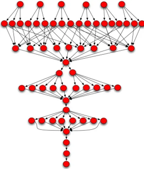
Three workflows containing 30, 60 and 100 tasks were designed inspired by the graph of the Montage workflow [5], a classic astronomical image mosaic workflow processing large images of the sky. Montage appears to combine sequential and parallel flows, making it relevant for such experiments. Our variants of the Montage workflow are illustrated in Figure 10, Figure 11 and Figure 12, and are respectively referred to as Workflow30t, that comprises 30 tasks over 10
levels (the level of a task is defined as the length of the path leading to it),Workflow60t, that
comprises 60 tasks dispatched over 13 levels, and Workflow100t made of 100 tasks of 19 levels. Our campaign has the following considerations:
1. Each task calls an actual web service.
2. Tasks at the same level have the same computation cost. 3. The results of these experiments are averaged over 10 runs.
Figure 11: Workflow 60-task graph.
Figure 12: Workflow 100-task graph.
Three different web services were built, presenting different rates of data exchanges, for one call of this service, namely 28 bytes for serviceA, 583 bytes for serviceB, and 3063 bytes for
serviceC. The definitions used for each workflow are available online1.
6.2
Managing Large Workflows
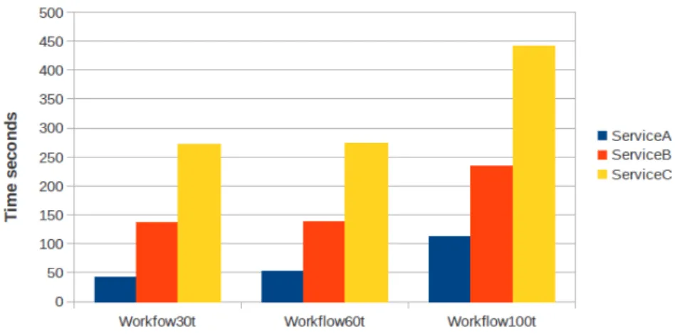
Let us first focus on the leftmost bar of the results of each workflow in Figure 13, i.e., the completion time of each workflow, but always using serviceA.
Figure 13: Performance results, complexity of workflows.
A first result is that the execution times, for the Workflow30t and Workflow60t, are quite similar. When looking at the workflows, this can be explained by the fact that when the total number of tasks increases, the parallelism is also increased. There is a higher number of tasks running in parallel, and the number of levels for Workflow60t (13 levels) in comparison with the
Workflow30t (10 levels) is not too high.
However, the Workflow100t performs less well than others, its graph shows a substantial increase of levels (19) and thus more sequentiality, thus increasing the workload of the workflow system responsible to coordinate the execution, as more patterns have to be applied.
6.3
Exchanging Data
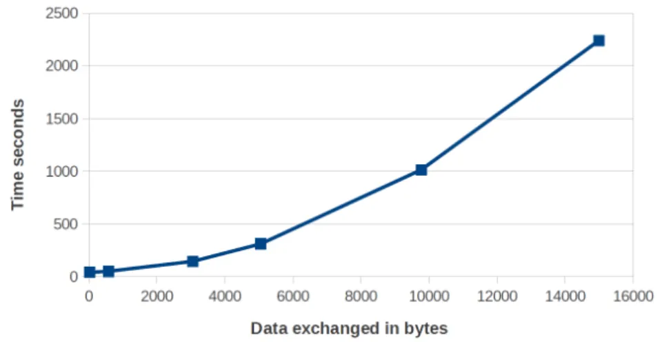
For the second experiment, we have dealt with different amount of data exchange. We processed six workflows based on the Workflow30t graph, whose tasks are bounded to the same web service. Note that, for each workflow, we measured the performance using a set of web services exchanging different amount of data for their execution. This set of services is composed by the three previously-mentioned services and by three other services. Thus, experiments were conducted with services requiring respectively 28, 583, 3053, 5053, 9773, and 15000 bytes of data exchange. The performance obtained according to the rate of data exchange is illustrated in Figure 14.
Figure 14: Performance results, data exchange.
As we can see in Figure 14, the increase in data exchange among tasks provokes an increase of the execution time, suggests a linear degradation of the performance when the size of information exchanged increases. Nevertheless, no bottlenecks have been experienced, even if it may appear with higher data rate. The degradation occurs because the information exchanged is considered itself as a molecule in our chemical model, to be transferred and processed in the multiset.
6.4
Workflow’s Complexity
We now focus on the evaluation of the workflow complexity. Informally, we consider as a complex workflow, a workflow having many patterns to be applied and a high rate of data exchange. The complexity also depends on the amount of data exchanged among tasks since these data have to be processed in applying some patterns. The results on the complexity can be deduced by looking at Figure 13.
A first observation is that the performance degradation among the three workflows binding their tasks to the different types of services. As we mentioned before, this difference is due to the increment of the amount of data exchange among tasks of any workflow. Thus, the Workflow30t using the serviceB or serviceA performs less well than the Workflow30t using the ServiceC. Secondly, the degree of complexity of the Workflow30t in comparison with the Workflow100t is high and leads to an important degradation which increases depending on the information transferred among the tasks. However, there is a slight improvement of the execution time for the Workflow60t against the Workflow30t, that is explained by the similarity of those workflows. Despite of the number of tasks participating in the Workflow60t, there is more parallelism and only a slight increases of sequentiality, thus reducing the execution time. Finally, Workflow100t containing tasks with the ServiceC presents an important increase of the execution time, coming from the significant increase of the size and processing time of the multiset.
6.5
Discussion
This series of experiments, by offering a proof of concept of the model, while showing its viability in actual deployments, highlights the benefits of a decentralized (chemistry-based) workflow system. Our workflow engine process large workflows with a reduced coordination overhead.
However, in our architecture, while the coordination is executed locally on each ChWS (here the coordination is shared among the nodes), the multiset remains a space shared by every ChWSes leading to potential scalability issues. Following this idea, our approach may experience some performance bottleneck when the rate of data exchange becomes very high. One possible response to this problem is a mechanism based on data files to store molecules.
Recall, beyond performance or optimization considerations, that the chemical models provide all the needed abstractions to naturally express both data-driven and complex control-driven execution, including particular features like cancellation. Please refer to [11] for more details. We consider the chemical abstraction as participating in the long term objective of improving the workflow execution models on emerging platform, like clouds, where the elasticity brings new modeling challenges.
7
Related Works
There is a vast literature related to the distributed execution of workflows. We observed two methods of distributed coordination approach. In the first one, nodes interact directly. In the second one, they use a shared space for coordination.
Earlier works proposed decentralized architectures where nodes achieve the coordination of a workflow through the exchange of messages [25, 16]. Recently, some works [6, 15, 27] shown the increasing interest in this type of coordination mechanism. In [6], the authors introduce service invocation triggers, a lightweight infrastructure that routes messages directly from a producing service to a consuming one, where each service invocation trigger corresponds to the invocation of a service. In [15], an engine is proposed based on a peer-to-peer application architecture wherein nodes (similar to local-engines) are distributed across multiple computer systems, but appear to the users as a single entity. These nodes collaborate, in order to execute a composite Web service with every node executing a part of it. Lately, a continuation-passing style, where information on the remainder of the execution is carried in messages, has been proposed [27]. Nodes interpret such messages and thus conduct the execution of services without consulting a centralized engine. However, this coordination mechanism implies a tight coupling of services in terms of spatial and temporal composition. Nodes need to know explicitly which other nodes they will potentially interact with, and when, to be active at the same time. Likewise, a distributed workflow system based on mobile libraries playing the role of engines was presented in [10]. The authors, however, do not give much details about the coordination itself, and where the data and control dependencies are located.
Our works deal with the information exchange among ChWSes by writing and reading the multiset. Then, the communication can be completely asynchronous since the multiset guarantees the persistence of data and control dependencies. This makes our approach more relevant in a loosely-coupled services environment, and able to deal with dynamic changes in the workflow.
Another series of works rely on a shared space to exchange information between nodes of a decentralized architecture, more specifically called a tuplespace [8, 14, 22]. Its origin can be found in the coordination data-driven languages such as Linda [12], as a parallel programming extension for programming languages for the purpose of separating coordination logic from pro-gram logic. Linda builds upon the notion of a tuplespace, which is a piece of memory shared by all interacting parties. Using tuplespace for coordination, the execution of a part of a workflow within each node is triggered when tuples, matching the templates registered by the respective nodes, are present in the tuplespace. In the same vein, works such as [18], propose a distributed architecture based on Linda where distributed tuplespaces store data and programs as tuples, allowing mobile computations by transferring programs from one tuple to another. However, the
chemical paradigm allows an increased abstraction level while providing support for dynamics. Based on this coordination method, works such as [8],[14] and [22] replace a centralized BPEL engine by a set of distributed, loosely coupled, cooperating nodes. In [8] and [14], the authors present a coordination mechanism where the data is managed using a tuplespace and the control is driven by asynchronous messages exchanged between nodes. This message exchange pattern for the control is derived from a Petri net expression of the workflow. In [14], the workflow definition is transformed into a set of activities, that are distributed by passing tokens in the Petri net. However, while in these works, the tuplespace is only used to store data information, our coordination mechanism stores both control and data information in the multiset, which is made possible by the use of the chemical execution model for the coordination of all data and control dependencies.
Recently, a work [22] uses a shared tuplespace working as a communication infrastructure, the control and data dependencies exchange among processes to make the different nodes interact between them. The authors transform a centralized BPEL definition into a set of coordinated processes using the tuplespace as a communication space. In contrast, the use of BPEL as coordination language hinders from expressing dynamic and self-adaptive behaviors.
As a more general comment, to our knowledge, these works do not provide software prototypes and experimental validation of their proposal.
8
Conclusion
Most of today’s approaches to the coordination of composite Web services are based on highly centralized architectures. Such systems present several drawbacks, mainly dealing with scala-bility, fault-tolerance, and privacy. In order to tackle these issues, it becomes today crucial to propose decentralized coordination mechanisms. However, current proposals for decentralized workflow coordination require tight coupling of services, and use workflow description languages that do not provide concepts for distributed workflow execution.
In this paper, we have proposed a high-level coordination mechanism allowing a distributed execution of composite Web services, based on the chemical metaphor. Our chemical program-ming paradigm expresses parallelism and autonomic behaviors naturally using a higher-order chemical language. We have introduced the notion of the chemical Web service, which encap-sulates a Web service. Through a shared multiset containing the information on both data and control dependencies needed for coordination, chemical Web services are co-responsible for carry-ing out the execution of a workflow in the composite services in which they appear. Spatial and temporal composition of services is achieved dynamically through this shared multiset. Their coordination is decentralized and distributed among individual Web service’s chemical engine executing a part of the workflow.
Through the deployment of a software prototype following these concepts, and its experimen-tal validation over an actual platform, we have been able to provide a proof of concept while showing its viability and identifying its performance limitations for its future improvements.
References
[1] Alonso, G., Mohan, C., Agrawal, D., Abbadi, A.E.: Functionality and limitations of current workflow management systems. IEEE Expert 12 (1997)
[2] Banâtre, J., Fradet, P., Radenac, Y.: Generalised multisets for chemical programming. Mathematical Structures in Computer Science 16(4), 557–580 (2006)
[3] Banâtre, J.P., Métayer, D.L.: The gamma model and its discipline of programming. Sci. Comput. Program. 15(1), 55–77 (1990)
[4] Banâtre, J.P., Priol, T., Radenac, Y.: Chemical Programming of Future Service-oriented Architectures. Journal of Software 4(7), 738–746 (2009)
[5] Berriman, G., Deelman, E., Good, J., Jacob, J., Katz, D., Kesselman, C., Laity, A., Prince, T., Singh, G., hu Su, M.: Montage: A grid enabled engine for delivering custom science-grade mosaics on demand. In Proceedings of SPIE Conference 5487: Astronomical Telescopes (2004)
[6] Binder, W., Constantinescu, I., Faltings, B.: Decentralized orchestration of compositeweb services. In: Proceedings of the IEEE International Conference on Web Services. pp. 869– 876. IEEE Computer Society (2006)
[7] Bolze, R., Cappello, F., Caron, E., Daydé, M.J., Desprez, F., Jeannot, E., Jégou, Y., Lanteri, S., Leduc, J., Melab, N., Mornet, G., Namyst, R., Primet, P., Quétier, B., Richard, O., Talbi, E.G., Touche, I.: Grid’5000: A large scale and highly reconfigurable experimental grid testbed. IJHPCA 20(4), 481–494 (2006)
[8] Buhler, P.A., Vidal, J.M.: Enacting BPEL4WS specified workflows with multiagent systems. In Proceedings of the Workshop on Web Services and Agent-Based Engineering (2004) [9] Chafle, G., Chandra, S., Mann, V., Nanda, M.G.: Decentralized orchestration of
compos-ite web services. In Proceedings of the 13th International World Wide Web Conference, (WWW2004) pp. 134–143 (2004)
[10] Downes, P., Curran, O., Cunniffe, J., Shearer, A.: Distributed radiotherapy simulation with the webcom workflow system. International Journal of High Performance Computing Applications 24, 213–227 (May 2010), ACM ID: 1773958
[11] Fernández, H., Tedeschi, C., Priol, T.: Self-coordination of Workflow
Execu-tion Through Molecular ComposiExecu-tion. Research Report RR-7610, INRIA (05 2011), http://hal.inria.fr/inria-00590357/PDF/RR-7610.pdf
[12] Gelernter, D., Carriero, N.: Coordination languages and their significance. Commun. ACM 35(2), 96–107 (1992)
[13] Leitner, P., Rosenberg, F., Dustdar, S.: Daios: Efficient dynamic web service invocation. IEEE Internet Computing 13(3), 72–80 (2009)
[14] Martin, D., Wutke, D., Leymann, F.: A novel approach to decentralized workflow enactment. In: Enterprise Distributed Object Computing Conference, IEEE International. pp. 127–136. IEEE Computer Society, Los Alamitos, CA, USA (2008)
[15] Micillo, R.A., Venticinque, S., Mazzocca, N., Aversa, R.: An agent-based approach for dis-tributed execution of composite web services. In: IEEE International Workshops on Enabling Technologies. pp. 18–23. IEEE Computer Society, Los Alamitos, CA, USA (2008)
[16] Nanda, M.G., Chandra, S., Sarkar, V.: Decentralizing execution of composite web services. In: Proceedings of the 19th conference on object-oriented programming, systems, languages, and applications. pp. 170–187. ACM (2004)
[17] Németh, Z., Pérez, C., Priol, T.: Distributed workflow coordination: molecules and reac-tions. In: Parallel and Distributed Processing Symposium, 2006. IPDPS 2006. 20th Inter-national (2006)
[18] Nicola, R.D., Ferrari, G., Pugliese, R.: KLAIM: a kernel language for agents interaction and mobility. IEEE Transactions On Software Engineering 24 (1997)
[19] Obrovac, M., Tedeschi, C.: On Distributing the Runtime of the
Chem-ical Programming Model. Research Report RR-7661, INRIA (06 2011),
http://hal.inria.fr/docs/00/60/41/34/PDF/RR-7661.pdf
[20] Protić, J., Tomasević, M., Milutinović, V.: Distributed shared memory. John Wiley and Sons (1998)
[21] Rosen, M., Lublinsky, B., Smith, K.T., Balcer, M.J.: Applied SOA: Service-Oriented Archi-tecture and Design Strategies. Wiley (Jun 2008)
[22] Sonntag, M., Gorlach, K., Karastoyanova, D., Leymann, F., Reiter, M.: Process space-based scientific workflow enactment. International Journal of Business Process Integration and Management 5(1), 32 – 44 (2010)
[23] Standard, O.: Web services business process execution language, (WS-BPEL), Version 2.0 (2007)
[24] Viroli, M., Zambonelli, F.: A biochemical approach to adaptive service ecosystems. Infor-mation Sciences pp. 1–17 (2009)
[25] Yan, J., Yang, Y., Raikundalia, G.: Enacting business processes in a decentralised environ-ment with p2p-based workflow support. In: Advances in Web-Age Information Manageenviron-ment, pp. 290–297 (2003)
[26] Yang, Y.: An architecture and the related mechanisms for web-based global cooperative teamwork support. Int. Journal of Computing and Informatics 24 (2000)
[27] Yu, W.: Consistent and decentralized orchestration of BPEL processes. In: Proceedings of the 2009 ACM symposium on Applied Computing. pp. 1583–1584. ACM, Honolulu, Hawaii (2009)