HAL Id: hal-01076925
https://hal.inria.fr/hal-01076925v2
Submitted on 23 Oct 2014
HAL is a multi-disciplinary open access
archive for the deposit and dissemination of
sci-entific research documents, whether they are
pub-lished or not. The documents may come from
teaching and research institutions in France or
abroad, or from public or private research centers.
L’archive ouverte pluridisciplinaire HAL, est
destinée au dépôt et à la diffusion de documents
scientifiques de niveau recherche, publiés ou non,
émanant des établissements d’enseignement et de
recherche français ou étrangers, des laboratoires
publics ou privés.
Distributed under a Creative Commons Attribution| 4.0 International License
VEP
Roberto G. Cascella, Stefania Costache, Florian Dudouet, Filippo Gaudenzi,
Yvon Jégou, Christine Morin
To cite this version:
Roberto G. Cascella, Stefania Costache, Florian Dudouet, Filippo Gaudenzi, Yvon Jégou, et al..
Multi-Cloud Portable Application Deployment with VEP. [Technical Report] Inria. 2014. �hal-01076925v2�
with VEP
Roberto G. Cascella1, Stefania Costache1, Florian Dudouet1, Filippo
Gaudenzi1, Yvon Jegou1, and Christine Morin1
Inria, Campus Universitaire de Beaulieu, 35042 Rennes, France {roberto.cascella | stefania.costache | florian.dudouet | filippo.gaudenzi | yvon.jegou | christine.morin}@inria.fr
Abstract. Leveraging the plethora of available Infrastructure-as-a-Service (IaaS) solutions proves to be a hard task for users who should face the complexity of dealing with heterogeneous systems, either in terms of resources or APIs. Application portability is the mean to reduce the burden of adapting applications for specific IaaS types and escape po-tential vendor lock-in. The Virtual Execution Platform (VEP) is a cloud middleware software that interfaces multiple IaaS clouds and presents end-users with an interface facilitating deployment and life cycle man-agement of distributed applications made up of several inter-networked virtual machines. This paper presents the design of VEP and experi-mental results that evaluate its scalability in deploying applications on OpenNebula and OpenStack clouds.
Keywords: Cloud computing; standards; resource management; inter-operability; distributed application deployment.
1
Introduction
Recently, cloud computing has seen a tremendous growth with its increasing adoption both in industry and in academia. Cloud computing relies on virtual-ization technologies, which offer several advantages over traditional data centers. On the one hand users can move their applications to the cloud freeing them-selves from the control and management of the infrastructure so that they can focus on the deployed services. On the other hand they can rent resources of cloud providers only when needed according to a pay-as-you-go pricing model reducing the cost of the infrastructure.
Although the cloud market is expanding fast, its growth may soon be hin-dered by different user concerns regarding lock-in within a single cloud commer-cial offer, data privacy issues and lack of performance predictability. In a nut-shell, users might lose confidence in the model and services offered by a cloud provider. These issues are more pronounced for SMEs, which are interested in using the cloud technology, since they cannot afford the initial barrier cost to acquire their own datacenters, while they fear moving entirely their business in the cloud without guarantees.
Cloud lock-in makes the deployment of applications on different providers difficult for users. This complexity comes from the fact that users must cus-tomize the application and its Virtual Machine Images (VMI) to a specific Infrastructure-as-a-Service (IaaS) type used by cloud providers. When the user wants to switch from a cloud provider to another, she has to repeat this cus-tomization, making difficult to escape vendor lock-in and limiting the portability of the application. However, IaaS cloud interfaces and management software are evolving, making the repetition of the customization step and the deployment of portable application hard to achieve. Many standards are now flourishing to facilitate interoperability across different cloud providers and improve the porta-bility of applications. The European Commission has seen the need to coordinate the jungle of standards to avoid the fragmentation of the digital market with the creation of a new Cloud standards co-ordination Task Group within ETSI [1].
Offering dependable services on top of a unreliable physical infrastructure is both a challenging task and an important feature to make cloud comput-ing attractive for users and organisations. Hence, the cloud provider is not only charged with the complexity of managing a potentially distributed infrastructure and dispatching the virtual machines (VMs) of the applications to the physical resources, but with the need to offer guarantees to customers transparently. This implies ensuring the availability of the computation resources and having strict guarantees specified in a negotiated Service Level Agreement (SLA). Deploy-ing applications under a SLA will make cloud computDeploy-ing a valid alternative to private data centers responding to users requirements in terms of availability, dependable application execution, and security.
This paper presents the Virtual Execution Platform (VEP) system, an open source management middleware for IaaS clouds that addresses the cloud lock-in and dependability problems. From the end-users perspective, VEP eases the deployment of distributed applications under the constraints of negotiated re-quirements, and at the same time offers advance reservation and pro-active fault tolerance services. From the cloud provider administrator point of view, VEP provides a REST interface [11] and a simple GUI for administrators to manage their data centers.
VEP novelty comes from the fact that it relieves users from adapting their applications to the used IaaS, thus enabling multi-cloud portable application deployment. Portability is achieved by hiding the complexity of heterogeneous IaaS clouds: users have to specify one application description document, in an OVF [7] format, that will be further used to deploy the application on different heterogeneous clouds. This makes possible in practice to use an OVF based ap-plication marketplace, where users can look for apap-plications or submit their own. Moreover, VEP allows users to specify Service Level Agreement (SLA) terms. These terms can include constraints regarding the used application resources, e.g., in terms of node placement and data geographical location, specified times for starting applications, which are further enforced through advance reserva-tion. Then, the VEP ensures that the providers’ resources are utilized as needed for offering an elastic and dependable cloud service to customers.
The primary use case of VEP is the Contrail [6] system, which develops an open source integrated approach to virtualization aiming at offering services for federating IaaS clouds and Platform-as-a-Service (PaaS) services on top of federated clouds. VEP manages the cloud provider services exposing the same API to the component offering federation services, thus enabling the deployment of an application over several heterogeneous cloud providers in a transparent way. As it provides a simple interface to access multiple IaaS cloud at the same time, VEP can also be used by PaaS providers. Developers can now focus on developing their services without the need of managing the IaaS complexity and the different heterogeneous solutions.
This paper is organized as follows. Section 2 describes related work. Section 3 gives an overview of VEP and its architecture and features. Section 4 presents results of running VEP on the Grid’5000 testbed [5] on top of two IaaS clouds (OpenNebula and OpenStack) and the Contrail use case for multi-cloud sup-port. Finally, Section 5 concludes the paper and discusses future improvement directions for VEP.
2
Related Work
Very few propositions currently exist to manage the whole application lifecycle at the IaaS level while offering portability support and resource placement under SLA terms.
The DMTF Cloud Infrastructure Management Interface (CIMI [8]) model de-fines a framework for the application life cycle management. CIMI applications can be generated from an OVF document but no support for SLAs is currently integrated. VEP implements part of the CIMI standard and extends it with SLA support. The OASIS Topology and Orchestration Specification for Cloud Appli-cations (TOSCA [14]) standard is also focusing on a multi-cloud approach. The portability of cloud applications is achieved thanks to an interoperable descrip-tion of applicadescrip-tion and infrastructure services, and there is the nodescrip-tion of SLA. In contrast with the purpose of VEP, TOSCA focuses more on the notion of service than on the cloud infrastructure management.
The CompatibleOne [2] project develops an open source cloud software for managing applications across multiple clouds supporting cloud brokering and cloud federations. CompatibleOne is a generic platform built upon OCCI where various cloud and service providers publish their offers and supports SLA nego-tiation and enforcement. No standards for applications description are currently supported.
VMware vCloud Suite [16] is a proprietary integrated solution for building and managing a complete cloud infrastructure. Applications in vCloud are for-matted in the OVF standard but there is not an integrated support for SLA. RightScale [3] is another proprietary cloud management platform that offers portability by automatically configuring the application for a specific cloud. The main advantage of VEP over this solution is the open source approach.
3
VEP – Virtual Execution Platform
VEP [4, 12, 13] is a cloud middleware software that interfaces IaaS cloud providers offering users a seamless way of managing multiple heterogeneous clouds. Cloud providers might have different means to manage VMs or networks, different im-age formats that can be deployed on a physical host, different interfaces, or different contextualization methods for the physical resources. VEP provides a uniform way of representing and managing the resources of a cloud provider.
VEP sits on top of IaaS management platforms such as OpenNebula, Open-Stack or any IaaS cloud providing an OCCI or EC2 interface. Users interact with VEP to deploy and manage their applications as a whole, while administrators use it to configure the IaaS cloud and limit the user access rights.
3.1 Application Description
In this section we describe how an application is described by the user and then how it is represented in VEP.
OVF description. To deploy an application in VEP, the user specifies the application characteristics in a document [7] edited in OVF format, i.e., a format for the packaging and distribution of software to be run in VMs. This OVF format allows users to deploy applications on heterogeneous clouds as it is not tied to any particular hypervisor or processor architecture. The user can use the OVF document to communicate to VEP the following information:
– References to external files necessary to build the application, e.g., disk im-ages. These references can be a filesystem path or a URL;
– VM disk images together with their image format; – Shared storage to be mounted in the VMs; – Virtual networks to be used by the VMs;
– VM templates defining the virtual hardware of the VMs, the VM disk images and the networks connected to the VMs;
– Virtual hardware specification,e.g., number of processors and cores, memory size, disks, network interfaces, etc. To improve portability, the format also supports alternative hardware descriptions, allowing the IaaS provider to select the configuration it supports, e.g., the disk image format;
– Contextualization data to be passed to the VMs at boot time, e.g., public key, IP, etc.
Resource Handlers. Using the OVF document, VEP deploys the user’s ap-plication in a virtual execution environment, i.e., a generic platform composed of virtual resources, e.g., VMs, network or storage. However, to be deployed on the infrastructure, this virtual execution environment needs to be mapped to a set of virtual resources provided by the IaaS management platform. These resources are specified in VEP through virtual resources handlers, which basically define different classes of resource configurations, by following the DMTF’s CIMI [10] standard1. Currently, VEP supports three types of handlers:
Fig. 1.Constrained Execution Environment (CEE)
– VM handlers describe the computational resources amount (e.g. memory, disk space, number of cores and core frequency) assigned to a VM;
– network handlers describe a specific network setup;
– storage handlers specify the type of storage for the application’s data (e.g., NFS or XtreemFS/GAFS [15]).
VEP handles the allocation of resources on the IaaS cloud by using these specified resource handlers. Multiple applications can be deployed inside the same virtual execution environment. A user can define her own execution environments using predefined resource handlers.
Constraint description. VEP allows users to also specify SLAs regarding the resources allocated to their applications, or choose from default ones. These SLAs are expressed as constraints on the virtual execution environment in which the application runs. Different types of constraints are supported in VEP con-cerning the placement or the number of virtual resources which can be allocated. For instance, constraints can specify the affinity to allocate VMs close to each other, e.g. on the same node or rack, in order to improve their network commu-nication, or anti-affinity to increase dependability, for instance to place VMs on different data centers or countries. These constraints together with the virtual environment, in which the application runs, compose a Constrained Execution Environment (CEE). These constraints are also applied to the virtual resource handlers, composing the CEE handlers. When an application is deployed, one of the CEE handlers is used to define the physical resources to allocate to the application’s VMs. This CEE handler can be explicitly specified in a deploy-ment docudeploy-ment or derived from default mapping rules of the application or of the CEE.
Figure 1 illustrates a CEE and the relation between constraints, virtual re-source handlers and the OVF description. In this figure there are two constraints: sameSwitch and 10Gb. The constraint sameSwitch is linked to all handlers of the CEE. To enforce this constraint, all physical resources allocated by the CEE
must be connected by the same L2 switch. The constraint 10Gb is linked to the handler largeVolune and to the handler l2Net: the physical volume resource where the volume is allocated must be connected to the L2 switch at 10 Gb/s.
3.2 Basic User-VEP Interaction
To run an application on VEP, a user has to perform three main steps: (i) submit a document containing a CEE description, using the OVF format [9] and possibly describing virtual resource handlers and constraints, i.e., SLAs, for the application resources; (ii) submit a deployment document to VEP and ask it to add a number of virtual resources to the application using the previously mentioned constraints; (iii) and then ask VEP to start the application.
VEP selects a set of nodes from the IaaS cloud on which application VMs are placed, and then it instructs the IaaS cloud manager to start the VMs. For starting the application, VEP might also perform additional operations. For ex-ample, a user might specify in the OVF document a path for her own VM image. In this case, VEP has to upload the user image to the IaaS cloud data storage. This operation is made at the first deployment. Once the image is added and stored, it is kept until the application is deleted. During the application runtime, the user can ask VEP to start more VMs, by submitting another deployment document, or stop the application.
3.3 VEP Architecture
VEP has been designed to be highly modular in nature with well defined internal APIs to facilitate the reuse of the software and/or updates. The VEP architec-ture, depicted in Figure 2, is composed of two main modules: the VEP-Core and the Scheduler. The VEP-Core represents the interface between the users and the IaaS cloud providers by managing user accounts and the representation of the IaaS resources. The Scheduler is in charge of scheduling the deployment of an application and allocating the physical resources such that users’ constraints are satisfied. We describe next these two components.
VEP-Core. VEP-Core is composed of a set of services, which are offered to users, and a set of internal modules. A set of native cloud drivers are used by the VEP-Core modules to communicate with the IaaS management platform.
Users can access the VEP-Core services based on their defined role in VEP: end-user and administrator. The administrator has access through a GUI inter-face to a set of Administrator Services.These services allow her to add datacenters to the VEP managed clouds and configure their resources, e.g. available nodes and the network topology. The user has access to a set of User Services, through a GUI interface, and a RESTful API. These services allow her to define applica-tion descripapplica-tion/deployment documents, deploy and manage applicaapplica-tions. The VEP-Core also relies on an Authorization/Authentication (Authz/Auth) service which authenticates users in the system. The authentication of users relies on a username and password which are then used to obtain X.509 certificates. The Authz/Auth module of VEP uses these certificates to verify internal access poli-cies that allow a user to share or protect her information/applications.
VEP-core
Scheduler
User Interface
GUI REST
Admin Services User Services
Cloud Drivers Scheduler Engine Constraints Manager Reservations Manager R E S T Appliance Manager DB Engine Authz Auth CIMI Manager S c h e d u le r C li e n t OVF toolkit GAFS Client D B E n g in e
Fig. 2.VEP architecture
Applications are managed by the Appliance Manager service. This module handles the application life-cycle, from submission, deployment to shutdown. An OVF Toolkit parses the application’s OVF document to determine which virtual resources are part of an application and the location of the VM images, and stores this information in a database (DB Engine). The CIMI Manager parses the application description and creates the virtual resource handlers. These handlers, together with the user-specified constraints are submitted to the Scheduler, to allocate physical resources and start application’s VMs. Finally, the VEP-Core users a GAFS Client to provide users shared XtreemFS storage that can be accessed from the application’s VMs.
Scheduler. The Scheduler is an independent module of VEP and provides a scheduling service to VEP through a REST interface. The core of the Sched-uler is represented by the Scheduling Engine, which allocates physical resources to VMs by communicating their placement to the IaaS management platform. A Constraints Manager enables placement constraints, as defined in the user CEE. To provide guarantees about resource availability, the Scheduler also han-dles advance reservation of resources before application deployment through its Reservations Manager service. Reservations are stored in a database so that VMs placement can be done according to reservation requests, resource availability and user-defined constraints.
3.4 VEP Features
We have previously described the architecture and services of VEP. This section presents first the unique selling proposition of the VEP system: multi-cloud (portability) and SLA support. Then the main features are summarised at the end of the section.
Portability support.VEP hides the complexity of heterogeneous IaaS clouds from the user, as the same application description (OVF) and constraints (CEE)
are used to deploy an application regardless of the underlying IaaS platform. End-users only need to submit the OVF document describing the whole appli-cation and create the CEE; then, VEP is in charge of allocating resources and start the application. The adoption of the OVF format by VEP also improves the user’s application portability with existing commercial systems from VMware, IBM, Oracle, Red Hat, systems that also support OVF.
SLA support. VEP provides users with resource SLA support during their application deployment through Contrail Constrained Execution Environments (CEEs), that allow users to specify constraints regarding their desired resources. These CEEs can be derived from a negotiated SLA or made available as tem-plates ready to be instantiated by users. The CEE can also be used to define mon-itoring configurations. This feature can be later exploited to evaluate whether SLA constraints are enforced; at the time of writing SLA enforcement is not currently supported and left for future work.
As part of the SLA support, VEP can also facilitate the elasticity of ap-plications, i.e., by adding or removing some of their resources, as required to meet their performance objectives. The elasticity support is facilitated by VEP through supporting two deployment modes of OVF applications: implicit and controlled. In an implicit mode, all OVF virtual resources are deployed and started; in a controlled mode a user can explicitly specify which and how many OVF virtual resources listed in a deployment document should be started. By submitting a new deployment document to an existing application, the user can add more resources during the application runtime.
In the previous paragraphs, we have presented the VEP support for portabil-ity and SLAs through CEEs. Other features of the Contrail VEP not extensively discussed in this section are: partial application deployment to allow a user to link the deployed application with an existing one; advance reservation to guarantee resource provisioning in the future; design support for application snapshots to improve dependability for long running applications.
4
Validation
In this section we describe the validation of VEP. We first discuss the evaluation of the prototype on a real testbed and then a use case of it.
4.1 Evaluation on the Grid’5000 Testbed
We deployed VEP [4] on the Grid’5000 testbed on top of two different IaaS cloud provider systems. The goal of this evaluation is to show that VEP can be used on top of different clouds and to measure its overhead.
Implementation. VEP is implemented in Java and consists of approximately 30,000 lines of code. Currently, VEP’s scheduler places VMs on the nodes in a round-robin fashion, starting from a randomly picked node. VEP stores all the user and application information in a database, for which, MySql is used.
0 200 400 600 1 20 40 60 80 100 Time (s) Number of VMs VEP create time IaaS create time
(a) OpenNebula 0 400 800 1200 1600 2000 2400 1 20 40 60 80 100 Time (s) Number of VMs VEP create time IaaS create time
(b) OpenStack
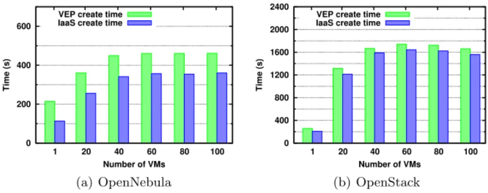
Fig. 3. Start time of an application composed of different numbers of VMs on (a) OpenNebula and (b) OpenStack.
Experimental Setup. We deployed VEP on the Rennes site from Grid’5000 on 30 nodes of two clusters: parapide and parapluie. The parapide cluster is com-posed of nodes with Intel Xeon L5420 processors (8 cores) and 32 GB of RAM. The parapluie cluster is composed of nodes with AMD Opteron(tm) 6164 HE processors (24 cores) and 48 GB of RAM. All the nodes are connected through a Gigabit Ethernet network. As an IaaS cloud manager we used OpenNebula 4.2 and OpenStack Grizzly. For both OpenNebula and OpenStack we used the default configuration. Optimizing the configuration of these software stacks is outside the scope of this paper. By default, as a storage for VM images, Open-Nebula uses a NFS server while OpenStack uses the local filesystem provided by its datastorage service, Glance.
To run an application on VEP we set up a VM disk image of 4.33 GB in QCOW2 format. In our experiments we submitted an OVF to VEP that instructs it to deploy VMs with this disk image. This OVF was used to create an application CEE composed of VMs with a capacity of 1 virtual core and 800 MB RAM.
Results. To measure the overhead of VEP, we deployed it on top of Open-Nebula and OpenStack and started applications composed of 1 to 100 VMs. For these experiments, the only impact on the results is the size of the VM image and not the type of application. We measured the time required to start the application using VEP (VEP create time), as well as the time required by the IaaS management platform to deploy the VMs (IaaS create time). We define these two time intervals as follows:
– VEP create time is the time interval from the application submission request registered by the VEP scheduler to the last VM boot;
– IaaS create time is the time interval from the processing of the first VM submission by the IaaS management platform to the last VM boot.
Figure 3 shows the time intervals needed for deploying an application com-posed of different number of VMs. We notice that, the VEP create time increases
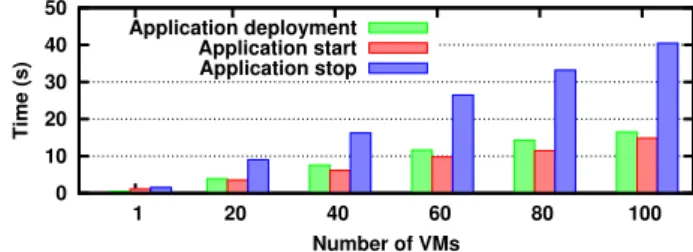
0 10 20 30 40 50 1 20 40 60 80 100 Time (s) Number of VMs Application deployment Application start Application stop
Fig. 4.Time for processing a user request composed of different numbers of VMs.
slowly, compared to the number of VMs to be deployed. This is due to the policy of the VEP scheduler and by fact that the IaaS management platform can deploy the VMs on the nodes in parallel. The difference between the VEP create time and the IaaS create time, which in our case is approximately 100 seconds, is mostly represented by the time required by VEP to upload the VM image to the IaaS storage. Other operations are also performed, like checking user privileges, inserting application’s information in the database and sending the appropriate requests to the IaaS management platform. Nevertheless, their cost is negligible. The IaaS create times are highly dependent on the used IaaS management platform. The main difference between the two IaaS management platforms is given by the mechanisms used to copy the VM image to the node on which the VM is booted. In OpenNebula, a frontend process connects to the nodes and creates a qcow image from a base image that is hosted on the shared NFS server. In OpenStack, each node downloads images through HTTP from the Glance service hosted on the frontend, and then a qcow image is created locally. In this case, the network becomes a bottleneck and leads to high VM deployment times.
We also measured the time required by VEP to process the different applica-tion operaapplica-tions, as seen by the user. Figure 4 shows the time for the usual oper-ations: (i) deploying, (ii) starting, (iii) and stopping an application. We haven’t included the time for submitting a CEE, as it is negligible. For deploying and starting an application, the user sees the cost of authentication, checking her constraints and storing the information in the database. The cost of starting the application is not noticed by the user, as this operation is done asynchronously by VEP. For stopping the application, the user notices the time required by VEP to delete the VM information from its database and to release the used resources from the IaaS management platform.
4.2 VEP Use Case: the Contrail Project for Multi-cloud Support
Contrail [6] is a European project which offers services for federating IaaS clouds, and Contrail PaaS (ConPaaS) services on top of federated clouds. The user relies on the Contrail federation to manage the access to individual cloud providers, such that an application can be seamlessly and automatically deployed over a multitude of heterogeneous providers. The providers can rely on different cloud technologies, exploit different hardware, or offer different types of guarantees.
The VEP system is integrated in the Contrail software stack and manages the Contrail cloud provider. The role of VEP is to seamlessly integrate the provider resources within the Contrail federation and provide virtualized distributed in-frastructures for the deployment of end-user applications independently from the underlying platform (currently OpenNebula or OpenStack).
VEP offers to Contrail a reliable application deployment platform, which is resilient to operational failures and which ensures that an application is deployed respecting QoS requirements, negotiated between the user and the Contrail fed-eration. The use of VEP allows to deploy a distributed application under the terms of a SLA over the resources of any of the supported IaaS providers. In Contrail, the elasticity of the application is also ensured by monitoring the us-age of the resources stated in a negotiated SLA, both within the cloud provider infrastructure and at the federation level. VEP receives direct instructions to add or remove resources.
The features and the degree of interoperability that the Contrail federation can exploit on each single cloud provider depend on the specific functionalities implemented at the cloud provider level. Interoperability is achieved through the VEP component.
VEP can offer multi-cloud support to PaaS services via the RESTful API. In the framework of the Contrail project, ConPaaS could use VEP to deploy PaaS services on any supported infrastructure.
5
Conclusion
In this paper we presented the VEP service, which considerably facilitates the deployment of distributed applications on heterogeneous clouds. VEP takes as input applications described as OVF packages and automates their deployment on IaaS clouds. From a unique OVF description cloud customers can deploy their applications on any IaaS cloud supported by the VEP service. Moreover, VEP contributes to increasing the confidence that customers put in cloud computing by taking into account SLA terms when deploying an application. Among SLA terms supported, we can cite virtual machine placement in the datacenter (clus-ter, rack, server) and data geographical location. VEP provides unique features like resource advance reservation and support for elasticity.
The current version of VEP has been deployed on OpenNebula and Open-Stack IaaS cloud management systems and tested on the Grid’5000 testbed. As a use case, VEP was integrated in the Contrail system. To our knowledge, VEP is one of the first systems implementing a CIMI-like cloud management interface. Through its features, VEP paves the way to an open cloud market by breaking the vendor lock-in. Moreover, VEP features make possible the usage of an OVF based application marketplace, where users can look for applications or submit their own. In our future work, we plan to interface VEP with public clouds such as Amazon EC2 and with any cloud providing an OCCI interface. We also plan to include mechanisms to snapshot applications for fault tolerance and mi-gration purposes, and monitoring mechanisms to enforce SLAs with automatic elasticity.
Acknowledgments This work is partially funded by the FP7 Programme of the European Commission in the context of the Contrail project under Grant Agree-ment FP7-ICT-257438. The experiAgree-ments presented in this paper were carried out using the Grid’5000 experimental testbed, being developed under the INRIA AL-ADDIN development action with support from CNRS, RENATER and several Universities as well as other funding bodies (see https://www.grid5000.fr).
References
1. Cloud standards coordination, http://csc.etsi.org/website/home.aspx 2. CompatibleOne: The Open Cloud Broker, http://www.compatibleone.org/ 3. RightScale, http://www.rightscale.com/
4. VEP: Virtual Execution Platform, https://project.inria.fr/vep/
5. Bolze, R., Cappello, F., Caron, E., Dayd´e, M., Desprez, F., Jeannot, E., J´egou, Y., Lanteri, S., Leduc, J., Melab, N., Mornet, G., Namyst, R., Primet, P., Quetier, B., Richard, O., Talbi, E.G., Touche, I.: Grid’5000: A large scale and highly re-configurable experimental grid testbed. International Journal of High Performance Computing Applications (2006)
6. Cascella, R.G., Blasi, L., J´egou, Y., Coppola, M., Morin, C.: Contrail: Distributed application deployment under sla in federated heterogeneous clouds. In: Future Internet Assembly. Lecture Notes in Computer Science, vol. 7858, pp. 91–103. Springer (2013)
7. Crosby, S., Doyle, R., Gering, M., Gionfriddo, M., Grarup, S., Hand, S., Hapner, M., Hiltgen, D., et.al: Open Virtualization Format Specification DSP0243 1.1.0 (Jan 2010), http://dmtf.org/standards/ovf
8. Davis, D., Pilz, G.: Cloud Infrastructure Management Interface (CIMI) Model and REST Interface over HTTP DSP-0263 (May 2012), http://dmtf.org/standards/ cloud
9. DMTF: Open Virtualization Format Specification. http://www.dmtf.org/ standards/ovf(2010)
10. DMTF: Cloud Infrastructure Management Interface (CIMI) Model and RESTful HTTP-based Protocol, An Interface for Managing Cloud Infrastructure (v1.0.1 DSP0263). http://www.dmtf.org/standards/cloud (2012)
11. Fielding, R.T.: Architectural styles and the design of network-based software archi-tectures. Ph.D. thesis, University of California, Irvine, Irvine - Irvine, CA 92697, USA (2000), http://portal.acm.org/citation.cfm?id=932295
12. Harsh, P., Dudouet, F., Cascella, R., Jegou, Y., Morin, C.: Using open standards for interoperability issues, solutions, and challenges facing cloud computing. In: 8th International Conference on Network and Service Management (CNSM) (2012) 13. Jegou, Y., Harsh, P., Cascella, R., Dudouet, F., Morin, C.: Managing OVF
ap-plications under SLA constraints on contrail virtual execution platform. In: 8th International Conference on Network and Service Management (CNSM) (2012) 14. OASIS: Topology and Orchestration Specification for Cloud Applications Version
1.0 (November 2013), https://www.oasis-open.org/committees/tosca/ 15. Stender, J., Kolbeck, B.: Requirements and Architecture of the Global Autonomous
File System. Deliverable D6.1, CONTRAIL Project (September 2011)
16. VMware: vCloud Suite for Cloud Computing & Cloud Management, http://www. vmware.com/products/datacenter-virtualization/vcloud-suite/