HAL Id: hal-01993154
https://hal.archives-ouvertes.fr/hal-01993154
Submitted on 24 Jan 2019
HAL is a multi-disciplinary open access
archive for the deposit and dissemination of
sci-entific research documents, whether they are
pub-lished or not. The documents may come from
teaching and research institutions in France or
abroad, or from public or private research centers.
L’archive ouverte pluridisciplinaire HAL, est
destinée au dépôt et à la diffusion de documents
scientifiques de niveau recherche, publiés ou non,
émanant des établissements d’enseignement et de
recherche français ou étrangers, des laboratoires
publics ou privés.
Tailoring Index-Modulation for uplink IoT and M2M
Networks
Julio Manco-Vasquez, Marwa Chafii, F. Bader
To cite this version:
Julio Manco-Vasquez, Marwa Chafii, F. Bader. Tailoring Index-Modulation for uplink IoT and M2M
Networks. IEEE Wireless Communications and Networking Conference (WCNC’2019), Apr 2019,
Marrakech, Morocco. �10.1109/WCNC.2019.8885713�. �hal-01993154�
Tailoring Index-Modulation for uplink IoT and M2M
Networks
Julio Manco-Vasquez
∗, Marwa Chafii
†, and Faouzi Bader
∗IETR/CentraleSupélec, Campus de Rennes,
Avenue de la Boulaie, 35510 Cesson-Sévigné, France∗.
Cergy-Pontoise University, ENSEA, ETIS,
CNRS, F-95000, Cergy, France†.
E-mails: [email protected]∗,
[email protected]†, [email protected]∗.
Abstract—The low complexity, low cost of implementation, as well as the spectral and energy efficiency, are key features for the development of the internet of things (IoT) networks. In this context, the introduction of index modulation on single carrier-frequency division multiple access (SC-FDMA-IM) has reported significant gains in terms of energy efficiency. In this paper, we evaluate an SC-FDMA-IM scheme tailored for IoT devices taking into account its complexity and performance. For that end, computational simulations and a complexity analysis for different detectors are carried out. Our results show that a significant bit error rate gain is obtained in comparison to a conventional SC-FDMA scheme, while maintaining a reduced computational complexity and power consumption.
Index Terms—Index modulation, SC-FDMA, narrow
band internet of things (NB-IoT), M2M communica-tions.
I. Introduction
IoT communications are forthcoming paradigms that will enable objects to communicate among them to provide different user services, and consequently a vast variety of applications is expected to be developed [2], [3]. On the other hand, it requires to change the entire paradigm of the legacy technology, for which it has recently attracted research interest.
To fulfill this gap, a low power wide area (LPWA) technology, has been conceived for providing key features suitable for IoT applications, such as low energy consumption and wide coverage at the expense of low data rates [1]. With the development of the aforementioned technology and the increasing demand of interconnecting mobile networks, some proposals for its standardization have been fomented. The third Generation Partnership Project (3GPP) is one of them, with narrow band-IoT
This work has received a French state support granted to the Enhanced PHY for cellular Low power communication IoT (EPHYL) project and managed by the National Research Agency under refer-ence Nb. ANR-16-CE25-0002-03.
(NB-IoT) standards in Release-13, as some of the latest propositions.
Moreover, some initial research efforts have been carried out to develop alternative modulation schemes more tailored for the targeted applications [7], [12], [13]. On the other hand, the concept of index modulation (IM) to carry extra information bits, has been explored for 5G wireless networks [4], [5], and recently proposed for IoT applications with significant gains in terms of energy and spectral efficiency [7]. Nevertheless, more research aspects such as the complexity, the cost of implementation as well as the attained BER performance still need to be addressed.
In the present work, we consider the SC-FDMA-IM scheme, as it has been reported to achieve energy efficiency. This scheme consists in the activation of a set of subcarriers to convey extra information. More specifically, a set of selected sub-carriers conveys the input data symbols, while keeping the rest of them inactive. The selection of sub-carriers is carried out by an index mechanism following the incoming information bits [4]. In this way, extra bits per symbol are transmitted, while at the same time, reducing the power consumption. The evaluation of the proposed SC-FDMA-IM scheme takes into account the requirements imposed by the NB-IoT standard, and the reported advantages in terms of energy efficiency in [7]. In this regard, we focus on the performance and the implementation aspects, where the detection and decoding process play an important role, not only in the bit error rate (BER) performance, but also in the cost of implementation. Several detection methods such as the maximum likelihood (ML) detection, the log-likelihood ratio (LLR) detector, and sparsity detectors (SD) are evaluated and examined. In addition, the impact of the channel coding and channel estimation errors is assessed in the attained performance. Our results point out that the SC-FDMA-IM scheme provides significant advantages in comparison to classical SC-FDMA.
!"#$% "#$% !"#$% &'()*+,-(./0$#-' 1-2+.%)2+! &'()*+,-(./0$#-' 1-2+.%)2+ &'()*+,-(./0$#-' 1-2+.%)2+" 3 !45-#'$4678 3 45-#'$4678 3!45-#'$4678 9.":022#)2 ,055#'; ! ۼ۴۴܂ 5-#'$4&678 < =((+:>:/#:+ 52)1#*
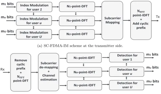
(a) SC-FDMA-IM scheme at the transmitter side.
!"!#"$%&'(%)' *+!)' !"!#"$%&'(%)' *+!)'! !"!#"$%&'(%)' *+!)', -*.#/))$!) 0!12/33$&4 5 67/&&!8 !+"$2/"$%& 2,.$"+ 2!.$"+ 2 .$"+ 9,13%$&"1: ;< 9!13%$&"1: ;< 9 13%$&"1: ;< ! =!2%>! #?#8$#' 3)!($@ 5 ۼ۴۴܂ 3%$&"1 ;<
(b) SC-FDMA-IM scheme at the receiver side.
Fig. 1: SC-FDMA-IM scheme for IoT devices
Furthermore, our study compares the performance of detectors commonly used in the literature such as the ML and LLR detectors, which have not been evaluated for the uplink communications of M2M and IoT devices in [7]. In this regard, the design of detectors concerning the sparsity of indexed signal allows us to obtain significant gains in terms of BER and complexity, when compared to the conventional detectors. Finally, the results with channel coding reveal that better coding strategies may be addressed in this context.
The rest of the paper is organized as follows. Section II describes the SC-FDMA-IM scheme, the examined detection methods are exposed in Section III, while the analysis of the performance and complexity are discussed in Section IV. Finally, the conclusions and future works are given in Section V.
II. System overview
A. SC-FDMA with index modulation
Let U be the number of users considered in our
scenario, and each user transmits mu bits, as illustrated
in Fig. 1(a) at the input of the index modulation block. In this SC-FDMA-IM scheme, each user u has been assigned
Nu subcarriers, that can be subdivided into Gu groups,
each one of length nu subcarriers: Nu = nuGu. Let ku
be the number of active subcarriers within each group (ku≤ nu), and Ku= kuGu the total number of allocated subcarriers.
For each SC-FDMA-IM symbol of duration T , a
stream of mu = Gu(mindu + m sym u ) bits is conveyed, where mind u = ⌊ log2(nu ku )⌋
is the number of bits to
be mapped to an index set of active subcarriers, and
msymb
u = kulog2(M) is the number of bits mapped to
M-ary constellation symbols.
It is worth mentioning that the index selection is implemented by user u using either a look-up table or
a combinatorial mapping 1. At this point, an N
u -point-DFT (discrete Fourier transform) is applied to an input
vector comprised ofM-ary symbols at active subcarriers,
and zeros at inactive subcarriers. The output follows a subcarrier mapping to establish the access mode of the
users. Eventually, an NF F T-point-IDFT (inverse discrete
Fourier transform) is applied for each user separately, and a cyclic prefix of sufficient length is appended. On the other hand, at the receiver side (See Fig.1(b)), a similar inverse procedure is performed. Nevertheless, in this case, a detection block is introduced in order to estimate the active index subcarriers, and to decode the
correspondingM-ary symbols.
B. Multiple access modes
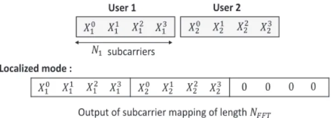
There are different ways to allocate subcarriers between users, and without loss of generality we focus on a localized subcarrier mapping. In this mode, the DFT outputs are placed in consecutive subcarriers, as depicted in Fig 2. In this illustrative example, the access mode for two users
U = 2 with Nu= 4 subcarriers and NF F T = 12 is shown. It is important to highlight the difference between the unused subcarriers due to the access mode and the inactive subcarriers related to index modulation. In this case the unused subcarriers may be used for other users, whereas
User 1 User 2
ܺଵ ܺଵଵ ܺଵଶ ܺଵଷ
Localized mode :
ܺଵ ܺଵଵ ܺଵଶ ܺଵଷ ܺଶ ܺଶଵ ܺଶଶ ܺଶଷ Ͳ Ͳ Ͳ Ͳ ܰଵsubcarriers
Output of subcarrier mapping of length ܰிி் ܺଶ ܺଶଵ ܺଶଶ ܺଶଷ
Fig. 2: Localized access mode for two users
the inactive subcarriers remain inactive during the whole transmission.
III. Detection methods for SC-FDMA-IM Let us consider an equivalent discrete channel in the frequency domain for each user u given by,
ru(α) = hu(α)xu(α) + w(α), α = 1, ..., Nu (1)
where ru is the received signal at the input to the
“detection for user u” block (See Fig. 1(b)), hu represents
the channel fading coefficients following a complex
Gaussian distribution CN (0, 1). On the other hand, xu
is the modulated sparse signal at the input of the “Nu
point-DFT” block (See Fig. 1(a)), and w ∼ CN (0, σ2
w)
the Gaussian noise with a variance, σ2
w.
In the proposed SC-FDMA-IM receiver, our goal is to detect the indices of the active subcarriers, and decode the corresponding information symbol. Relevant performance criteria for IoT applications have been addressed in our previous study [7], where suitable groups of subcarriers achieving the same spectral efficiency (i.e. data rate over allocated bandwidth) of an SC-FDMA scheme have been proposed. In fact, it suggests to select the lowest number of active subcarriers among the proposed groups in order to attain a 50% in energy efficiency [7]. For that end, we investigate different detectors considering the reported setup in [7], which meets the required features for IoT devices.
For the problem of uplink communications and for notational simplicity, we omit the subindex u to describe the following detection methods. In addition, we denote
rg the received signal corresponding to the g
th group of
subcarriers, i.e. rg={r(1), r(2), ..., r(n)}, for g = 1, ..., G.
On the other hand, Ig denotes a set given by {ig
1, ..., i g k} with ig γ ∈ {1, ..., n} for γ = 1, ..., k, s g is a set given by {sg 1, .., s g k} with s g
γ an M-ary symbol, and x
g ∈ {0, sg}. Then, the detection method aims to estimate the indices
ˆ
Ig, and the corresponding symbols ˆsg, at each group of
the user.
1) ML detector: it is given by, (ˆIg, ˆsg) = arg min Ig,sg k ∑ γ=1 rg(igγ)− hg(igγ)sgγ 2 (2)
where hg and sg refer to the channel coefficients and
data symbols respectively, both for the gth group of
subcarriers. Note that with this detector a joint decision
on the active indices Ig and constellation symbols sg
involves searching among all possible combinations. 2) Log-Likelihood Ratio (LLR) detector: In this detection, the ratio of a posteriori probability of the received symbols determines, if it is an active subcarrier. It is given by,
λ(α) = ln ∑M χ=1P (x g(α) = S χ|rg(α)) P (xg(α) = 0|rg(α)) , α = 1, ..., n. (3)
where Sχ is an M-ary symbol and large values of
λ(α) indicate active subcarriers. Once the set of active
subcarrier indices is obtained, an ML detection for the
demodulation of the M-ary symbol is straightforwardly
applied.
3) Sparsity detector (SD): since the received signal contains few active subcarriers, we resort to the notion of compressed sensing (CS) to exploit the sparse property of this signal, where a k-sparse signal x is estimated,
such that r ≈ Φx, being Φ a measurement matrix [11].
To solve this problem, an orthogonal matching pursuit (OMP) algorithm [10] has been adopted. In fact, it has reported to perform well for sparse-signal estimation, while featuring a low-complexity implementation [8], [9]. For purposes of clarity, here we reproduce a summary of the implemented algorithm:
1: procedure OMP algorithm
2: Input: rg, Φ, k iter 3: Initialize: y0= rg, x0= 0,I g 0 =∅, 4: for t = 1 : kiter do 5: bt= ΦTyt−1 6: c = arg maxˆ c|[bt]c| / ∥[Φ]c∥ 7: Itg =Itg−1∪ ˆc 8: xˆgt = [ ΦIg t ]† rg 9: yt= rg− Φˆx g t 10: end for 11: Output: ˆxgt 12: end procedure
where Φ refers to the measurement matrix given by
the DFT matrix, kiter the number of required iterations
and ˆxgt is the estimated sparse signal. Note that, the
algorithm requires a real-value signal at the input, then the receiver complex signal is converted into a real one by concatenating the real and imaginary part. Finally,
after estimating the active subcarriers an M-ary symbol
is demodulated by applying an ML detection to the estimated sparse signal.
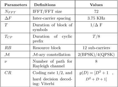
TABLE I: Parameter settings for SC-FDMA
Parameters Definitions Values
NF F T IFFT/FFT size 72 ∆F Inter-carrier spacing 3.75 KHz T Duration of block of symbols 1/∆ F TCP Duration of cyclic prefix T /8
RB Resource block 12 sub-carriers
M M-ary constellation 2(BPSK)/4(QPSK)
ν Number of path for
Rayleigh channel
8
CR Coding rate 1/2, and g(D) = [D2+ 1 ,
hard decision decod-ing: Viterbi
D2+ D + 1]
More practical approaches can be proposed by considering the magnitude of I/Q received waveforms, which are attractive due to their low complexity. Here, we evaluate the average of the I/Q received waveforms, i.e. rg
aveg = (|Real{rg}| + |Imag{rg}|)/2, to search the maximum values among n subcarriers, and estimate the
Ig indices. It is denoted as SD MAX, and it follows an
ML detector for the demodulation of symbols xg.
IV. Performance analysis
In this section, we address the performance of the exposed detectors, i.e. the LLR, the ML, and the sparsity detectors (SD and SD MAX). The parameters described in Table I and a minimum mean square error (MMSE) equalization are employed for the proposed SC-FDMA-IM scheme. In order to have the same spectral efficiency, when compared to the classical SC-FDMA scheme, we have considered one resource block (RB) per user. The RB comprises three groups G = 3 of subcarriers, and one active subcarrier k = 1 out of four subcarriers n = 4. It is important to highlight here that, the adopted setup for the RB (G = 3, k = 1 and n = 4) provides a significant gain of 50% in terms of energy efficiency.
In Fig. 3, the obtained BER performances among the aforementioned detectors are compared for the same
coding rate (CR) 1/2, with BPSK symbols (M = 2). In
this way, we study the attained performance of commonly reported detectors in the literature such as the LLR and ML detectors, and whose results are later used for purposes of comparison. In this example, the SD requires
only one iteration kiter = 1, and it achieves a better
performance by attaining a gain of 1.5 dB in terms of
Eb/No for a BER = 10−4 in comparison to the other
detectors. On the other hand, the LLR and ML detectors
obtain similar results, with a slightly difference for higher SNRs. We think that a formal proof of the obtained gains is out of the scope, however, it is worth mentioning that
SD with kiter = 1 only aims searching a real value (due
to BPSK symbols), which is exploited by looking for the active index in the real part of the received signal,
whereas the LLR and ML detectors evaluate eachM-ary
symbol to estimate the active subcarrier.
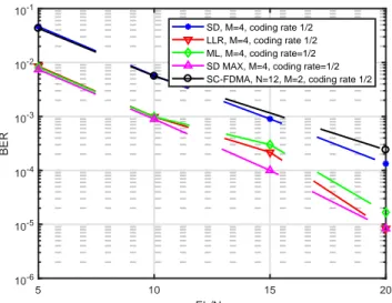
A BER comparison between an SC-FDMA scheme and our SC-FDMA-IM proposal is depicted in Fig. 4. It is evaluated using the channel coding with a CR of 1/2 (See Table I for details), and the same spectral efficiency (bps/Hz). The last criterion is carried out by conveying
QPSK symbols (M = 4) and BPSK symbols (M = 2) in
N = 12 subcarriers for the SC-FDMA-IM and SC-FDMA,
respectively. Our evaluation shows that the SC-FDMA is outperformed by the SC-FDMA-IM scheme for many of the exposed detectors. On the other hand, regarding the performance of the detection methods, it is observed that the SD approach cannot obtain a better performance. This can be explained from the fact that SD needs to reconstruct both the real and imaginary part of a QPSK
symbol (kiter = 2) which degrades its performance. On
the other hand, a significant improvement of the SD MAX approach over the other detectors is obtained, since it is able to exploit the sparse features of the received signal.
The impact of channel coding is also explored in Fig. 5, where all considered detectors perform worse than their coding counterpart. Note, however, that the obtained gains are rather smaller, and therefore it suggests to devise new coding strategies.
Finally, Fig. 6 plots the detection performance for a poor channel estimation. It is carried out by adding noise
to the channel estimation as he = h + ne, where ne
follows a normal distribution with a σ2
e variance. In this
case, the BER performance is degraded. For instance, the result for the LLR detector labeled with “LLR + He” (i.e. with channel errors) suffers an important performance degradation if compared to the LLR detector with accurate channel estimation (See as “LLR” in Fig. 6). On the other hand, note that the behavior of the detectors are quite similar, and the SD shows a slightly improvement over the LLR and ML detection for an
Eb/No = 20 dB. However, for higher SNRs, an error
floor is observed due to the introduced errors in channel estimation.
A. Complexity Analysis
Due to the existence of group of subcarriers, the search space is in general reduced for looking for the active
indices, and consequently its complexity. Nevertheless,
5 10 15 20 Eb/No 10-5 10-4 10-3 10-2 BER LLR, M=2, coding rate 1/2 SD, M=2, coding rate 1/2 ML M=2, coding rate=1/2
Fig. 3: The BER performance of the SC-FDMA-IM scheme
for the LLR and ML detectors, and SD. The scheme is imple-mented by using random interleavers,M = 2, and CR of 1/2.
5 10 15 20 Eb/No 10-6 10-5 10-4 10-3 10-2 10-1 BER SD, M=4, coding rate 1/2 LLR, M=4, coding rate 1/2 ML, M=4, coding rate=1/2 SD MAX, M=4, coding rate=1/2 SC-FDMA, N=12, M=2, coding rate 1/2
Fig. 4:A BER comparison between an SC-FDMA withM = 2
and SC-FDMA-IM withM = 4 scheme for the same spectral efficiency. Random interleavers are implemented for the SC-FDMA-IM scheme, both of them employ the same CR of 1/2, while LLR and ML detector, as well as the SD are examined.
the addressed technology has been studied. To compare the computational complexity, we consider the number of complex multiplications (NCM) as the performance metric, and the aforementioned setup given by n = 4,
k = 1, G = 3 and U = 1.
The comparison results are summarized in Table II
for low order modulations, i.e. M = 2 and M = 4, and
it is observed that the ML and LLR detectors obtain
a similar computational load. This can be explained
by the fact that grouping the subcarriers into G groups
5 10 15 20 Eb/No 10-5 10-4 10-3 10-2 10-1 BER ML, M=4, coding rate=1/2 ML, M=4, ML M=2, coding rate=1/2 ML, M=2 LLR, M=2, coding rate 1/2 LLR, M=2
Fig. 5: Impact of channel coding in the attained BER
per-formance for the proposed SC-FDMA-IM scheme. For two detectors: LLR and ML with and without CR of 1/2.
5 10 15 20 Eb/No 10-5 10-4 10-3 10-2 10-1 BER
LLR & He, M=2, coding rate 1/2 LLR , M=2, coding rate 1/2 ML & He M=2, coding rate=1/2 ML M=2, coding rate=1/2 SD & He, M=2, coding rate 1/2 SD, M=2, coding rate 1/2
Fig. 6:BER performance for SC-FDMA-IM with errors in the
channel estimation and CR of 1/2. A channel h to noise ne ratio of 15 dB given by 10 log10(σ2h/σ
2
e) is considered.
and applying the index modulation independently on each group reduces the search space of the subcarrier index. In fact, for a large number of subcarriers it is expected that an ML detection requires to search over all possible combinations of the indices, which makes it impractical for its implementation. In the same way, an undefined set of active indices not included in the original indexed mapping table is often obtained with an LLR detector. Nevertheless, these aspects are bounded due to the targeted configuration. On the other hand, the SD
provides a significant reduction for M = 2, since it only
requires one iteration, while SD MAX does not require implementing complex multiplications, since it only looks
for the maximum values in a reduced search space. TABLE II: Computational complexity
Detectors NCM M = 2 M = 4
LLR Gn(3M + 1) + G3M 102 192
ML G12M 72 144
SD Gn2+ G3M 66 84
V. Conclusions
In this paper, we have proposed an SC-FDMA-IM scheme for IoT devices, and studied several performance aspects including BER and implementation complexity for several detector schemes. Unlike an SC-FDMA scheme, it has shown to provide significant gains not only in terms of energy efficiency, but also in the attained BER performance, and with a low computational cost. For that end, several detectors have been assessed taking into account the impact of the channel coding and errors in the channel estimation, and whose results suggest to exploit the sparsity features of the received signal. Furthermore, at the light of our results the design of novel coding strategies to further improve our proposal seems to be a promising research topic.
References
[1] Usman Raza, Parag Kulkarni, and Mahesh Sooriyabandara. “Low Power Wide Area Networks: An Overview,” IEEE Com-munications Surveys & Tutorials, 2017.
[2] Hamidreza Shariatmadari, Rapeepat Ratasuk, Sassan Iraji, Andrés Laya, Tarik Taleb, Riku Jäntti, and Amitava Ghosh. “Machine-type communications: current status and future per-spectives toward 5G systems,” IEEE Communications Maga-zine, 53(9):10–17, 2015.
[3] Nitin Mangalvedhe, Rapeepat Ratasuk, and Amitava Ghosh. “NB-IoT deployment study for low power wide area cellular IoT,” In Personal, Indoor, and Mobile Radio Communications (PIMRC), 2016 IEEE 27th Annual International Symposium on, pages 1–6. IEEE, 2016.
[4] Ertugrul Basar, Ümit Aygölü, E. Panayırcı, and H Vincent Poor. “Orthogonal Frequency Division Multiplexing with Index Mod-ulation,” IEEE Transactions on Signal Processing, 61(22):5536– 5549, 2013.
[5] E. Basar. “Index modulation techniques for 5G wireless net-works,” 54(7):168–175, 2016.
[6] Marwa Chafii, Justin P Coon, and Dene A Hedges. “DCT-OFDM with Index Modulation,” IEEE Communications Let-ters, 2017.
[7] Marwa Chafii, Faouzi Bader, Jacques Palicot. “SC-FDMA with Index Modulation for M2M and IoT Uplink Applications,” IEEE Wireless Communications and Networking Conference (WCNC), April, Barcelona, Spain. 2018.
[8] J. Choi. “Single-carrier index modulation and CS detection,” IEEE International Conference on Communications (ICC), May. 2017.
[9] J. Choi. “Sparse index multiple access for multi-carrier systems with precoding,” Journal of Communications and Networks (WCNC), June. 2016.
[10] S.-J. Kim, K. Koh, M. Lustig, S. Boyd, and D. Gorinevsky, “An interior point method for large-scale l1-regularized least squares,” IEEE J. Sel. Topics. Signal Procss., vol. 1, pp. 606– 617, Dec. 2007.
[11] E. Candes and M. B. Wakin, “An introduction to compressive sampling,” IEEE Signal Processing Magazine., vol. 25, no. 2, pp. 21–30, 2008.
[12] E. Soujeri and G. Kaddoum and M. Au and M. Herceg. “Fre-quency Index Modulation for Low Complexity Low Energy Communication Networks,” IEEE Access, vol. 5, pp. 23276-23287, 2017.
[13] L. Song and S. Wu and H. Wang. “SIMPLEX: Symbol-Level Information Multiplex,” IEEE Internet of Things Journal, vol. 3, no. 5, pp. 757-766, Oct. 2016.