Science Arts & Métiers (SAM)
is an open access repository that collects the work of Arts et Métiers Institute of
Technology researchers and makes it freely available over the web where possible.
This is an author-deposited version published in: https://sam.ensam.eu Handle ID: .http://hdl.handle.net/10985/17208
To cite this version :
Keitaro YANAGIHARA, Duc Tan VU, Ngac Ky NGUYEN, Jinlin GONG, Eric SEMAIL, Tiago José DOS SANTOS MORAES - Fault-tolerant Control for 7-phase Non-sinusoidal Permanent Magnet Machines with One Opened Phase - In: The 2019 International Symposium on Electrical and Electronics Engineering (ISEE 2019), Viêt Nam, 2019-10-10 - The 2019 International Symposium on Electrical and Electronics Engineering (ISEE 2019) - 2019
Any correspondence concerning this service should be sent to the repository Administrator : archiveouverte@ensam.eu
1
Fault-tolerant Control for 7-phase Non-sinusoidal
Permanent Magnet Machines with One Opened
Phase
Keitaro Yanagihara1, Duc Tan Vu1, Ngac Ky Nguyen1, Jinlin Gong2, Eric Semail1, Tiago Jose dos Santos Moraes1
1Univ. Lille, Arts et Metiers ParisTech, Central Lille, HEI, EA 2697
- L2EP - Laboratoire d’Electrotechnique et d’Electronique de Puissance, F-59000 Lille, France
2Shandong University
School of Electrical Engineering, Jinan 250061, China
Abstract—This paper presents new fault-tolerant control
strategies for field-oriented control of 7-phase non-sinusoidal permanent magnet (PM) machines supplied by voltage source inverters (VSI). Single phase open-circuit fault is considered. The proposed strategies aim at finding waveforms of current references in natural frame in the way that post-fault currents create the same rotational magnetomotive force (MMF) as in healthy mode. Therefore, in the faulty mode, average torque can be maintained if no current limits are set. The proposed strategies are validated and compared to a previous strategy by numerical results in terms of joule losses, maximum RMS and peak phase currents, maximum phase voltage as well as their controllability with PI controllers.
Keywords—fault-tolerant control, non-sinusoidal multiphase machine, retro-design concept, joule losses, controllability with PI controllers
I. INTRODUCTION
Multiphase machines receive growing interests for high-power applications such as electrical vehicles, ship propulsion systems and aircrafts. As the number of phases increases, current per phase decreases with a given power. Thus, high power low-voltage applications can be more easily implemented. Furthermore, thanks to the additional degrees of freedom, these machines can operate even if one or two phases are lost without any additional components [1-3]. The objective of the fault-tolerant torque control is to maximize the average torque while minimizing torque ripples, additional joule losses and the rises in currents and voltages.
There have been many studies on fault-tolerant control for one or two-phase open-circuit faults for machines with a high number of phases. The proposed methods can be generally classified into two types of approaches. The first approach is to look for the current references which maximize the average torque value and minimize torque ripples. In order to achieve both objectives, cost functions are defined [4-7]. The second approach is to focus on preserving magnetomotive force (MMF) of the machine in post-fault conditions. In healthy mode, phase currents create a rotational MMF which leads to a constant torque. However, this condition does not exist anymore if one or two phases are open-circuited. The second approach was firstly presented by Fu and Lipo in [8]. The authors determined the current references in natural frame which creates the rotational MMF when one phase is opened. The mathematical expressions of remaining phase currents are given by defining and solving a system of equations
expressing the relation between MMF and the phase currents. However, only sinusoidal machines have been studied. If the machines have more than one harmonic of back-EMF, the method in [8] cannot give a ripple-free torque as in healthy mode.
Study [9] performed a fault-tolerant control strategy of 7-phase non-sinusoidal machines. The strategy is proposed to find current references in − frame by using the vectorial approach. However, the controllability of the strategy has not been considered and compared to other existing methods. To preserve the same MMF as in healthy mode, it is also possible to modify the transformation matrices by using reduced-order transformation matrices instead of modifying the current references in d-q frames [10, 11]. However, most of these papers are only applicable for sinusoidal machines. Moreover, the determination of the new transformation matrices for different faulty phases are complicated.
Studies [12, 13] propose several methods to obtain the maximal torque under current and voltage limits using offline optimization. By this way, the maximal torque is achieved while the maximal peak or RMS values of phase currents and peak phase voltages are limited in all modes of operation. These methods have advantages in the sizing of the inverter, especially in flux-weakening operation. Nevertheless, due to a dramatic increase in RMS and peak currents in post-fault conditions, the obtained torques in faulty modes are much smaller than in healthy mode if the current limit is set. Additionally, the controllability of currents in the proposed strategies has not been mentioned.
In this paper, two new strategies for fault-tolerant control of 7-phase PM machine are presented. These strategies are to find the current references expressed in natural frame which create a rotational MMF. The strategies are applied to a 3-rotor 7-phase non-sinusoidal PM machine, which is an ideal candidate for traction drives with high torque density due to a strong third harmonic of back-EMF. The proposed strategies are compared with one of the strategies proposed in [12, 13] by numerical results in terms of joule losses, maximal RMS and peak phase currents and maximal peak phase voltage as well as the controllability with proportional-integral (PI) controllers in d-q frames.
This paper is organized as follows: the model of the 7-phase machine is described in section II; the proposed fault-tolerant control strategies are shown in section III; section IV presents simulation results and analyses.
2 [ × ] = ⎣ ⎢ ⎢ ⎢ ⎢ ⎢ ⎢ ⎢ ⎢ ⎢ ⎢
⎡√ cos (0) sin (0) cos (0) sin (0) cos (0) sin (0)
√ cos sin cos sin cos sin √ cos sin cos sin cos sin √ cos sin cos sin cos sin √ cos sin cos sin cos sin
√ cos sin ( ) cos sin cos sin
√ cos sin cos sin cos sin ⎦
⎥ ⎥ ⎥ ⎥ ⎥ ⎥ ⎥ ⎥ ⎥ ⎥ ⎤ (4)
II. MACHINE MODELLING
A. 7-phase machine modelling
These following assumptions are considered to model the machine: seven phases of the machine are equally shifted; the magnetic circuit saturation is not considered in calculations of back-EMFs and fluxes; iron losses and salient pole effects are not considered in this study. Thus, the voltage vector can be expressed in the natural frame as follows:
= . + [ × ] + (1)
where , and are the 7-dimentional vectors of phase voltages, currents and back-EMFs respectively; is the stator resistance; [ × ] is the 7 × 7 stator inductance matrix.
The torque created by the machine can be expressed as:
= . (2)
where is the 7-dimensional speed-normalized back-EMF vector (SN-EMF) in natural frame.
⎣ ⎢ ⎢ ⎢ ⎢ ⎢ ⎢ ⎡ ⎦ ⎥ ⎥ ⎥ ⎥ ⎥ ⎥ ⎤ = [ × ] ⎣ ⎢ ⎢ ⎢ ⎢ ⎢ ⎡ ⎦ ⎥ ⎥ ⎥ ⎥ ⎥ ⎤ (3)
Using the Clarke transformation matrix (4), the 7-phase machine is decoupled into one zero-sequence machine FM0 and three 2-phase fictitious machines: FM1, FM2 and FM3 [14]. Each machine is associated to a family of odd harmonics as presented in Table I. Equation (3) shows the transformation of currents from natural frame ( ) to − frames. If Park transformation matrix is applied, the currents in − frames are transformed into d-q frames. Ideally, these currents are constant if each fictitious machine only consists of one harmonic. For example, there is only seventh harmonic in FM0, first harmonic in FM1, only fifth harmonic in FM2 and only third harmonic in FM3.
The sum of the torques created by the fictitious machines gives the total torque of the machine as expressed in (5).
= ∑ . (5)
where and are respectively the speed-normalized back-EMF and current vectors in rotating frames of the fictitious machine k.
B. Retro-design concept of the 7-phase machine
The 3-rotor 7-phase non-sinusoidal PM machine (Fig. 1) under this study has two axial rotors and one radial rotor. The
machine is designed considering double polarity [15]. As a result, this machine has a strong third harmonic component of back-EMF. If the machine is supplied by fundamental and third harmonic currents, the proportion of the torque created by the third fictitious machine (FM3) becomes more important, enabling to increase torque density of the considered machine.
Furthermore, the machine is designed to have no harmonics of back-EMF in the zero-sequence and second fictitious machine (FM0 and FM2). By this way, FM0 and FM2 cannot create any torque. Therefore, their currents can be used for fault-tolerant control without any negative impacts on the global torque of the machine (for example torque ripples). It means that more degrees of freedom for control has been added. Thus, the global torque of the 3-rotor 7-phase machine is created only by first and third fictitious machines (FM1 and FM3).
The back-EMF of the machine is obtained by finite element method. Then, Discrete Fourier Transformation is applied to analyze the harmonic spectrum in the back-EMF waveform. Then, back-EMFs can be expressed as the sum of several harmonics in (6).
= − ∑ . sin (ℎ( − ( − 1) ) − ) (6) where is the speed-normalized back-EMF of phase j;
is the amplitude of harmonic h; is the electrical angle; is the initial phase angle of harmonic h.
Fig. 2 shows that fundamental and third harmonics of back-EMF account for the highest proportions in the harmonic spectrum. The speed-normalized amplitudes of fundamental and third harmonic back-EMFs are 0.388V/rad/s and 0.47V/rad/s respectively. Other harmonics having the amplitudes less than 5% of the fundamental component can be neglected.
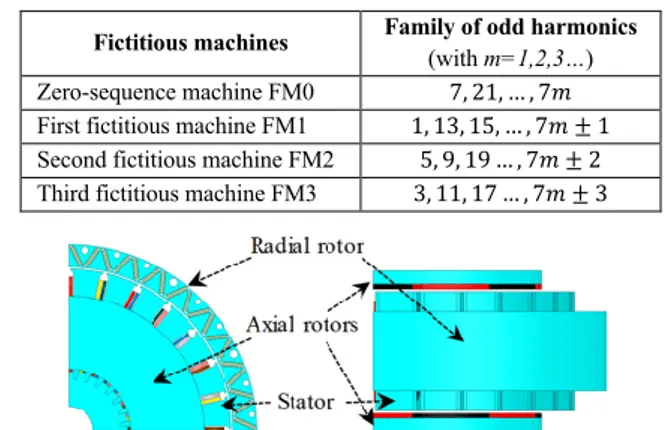
TABLE I. HARMONIC CHARACTERIZATION OF FICTITIOUS MACHINES
Fictitious machines Family of odd harmonics (with m=1,2,3…) Zero-sequence machine FM0 7, 21, … , 7 First fictitious machine FM1 1, 13, 15, … , 7 ± 1 Second fictitious machine FM2 5, 9, 19 … , 7 ± 2 Third fictitious machine FM3 3, 11, 17 … , 7 ± 3
3 Fig. 2. Harmonic spectrum of the back-EMF and waveforms of the
simulated and estimated speed-normalized back-EMFs
III. FAULT-TOLERANT CONTROL STRATEGIES FOR 7-PHASE NON-SINUSOIDAL MACHINES
A. Basic ideas of proposed strategies
In healthy mode, the three fictitious machines are decoupling, so the current controls of fictitious machines are independent. Due to the aforementioned design, to minimize the joule losses, the current in the zero-sequence machine ( ) and second machine ( , ), which cannot produce torque, are kept to zero. In contrast, in the other machines, the fundamental and third harmonic currents are used to generate torque by the maximum torque per ampere (MTPA) strategy. Therefore, the ratio between the third harmonic current over the fundamental one should be the same as of the back-EMFs as shown in (7). Because of constant values in d-q frames, PI controllers can be applied to control the d-q currents effectively.
= (7)
where and are the constant q-axis currents in FM1 and FM3 respectively.
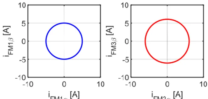
In addition, the fundamental and third harmonic components of currents in − frames must form circles as shown in Fig. 3, which creates a rotational MMF. The fundamental and third harmonic − currents are expressed in terms of d-q currents as shown in (8).
⎩ ⎪ ⎨ ⎪ ⎧ = − . sin ( − ) = . cos ( − ) = − . sin (3 − ) = . cos (3 − ) (8)
When one phase is open-circuited, all the − currents cannot be under control due to the lack of degrees of freedom. In other words, the three fictitious machines are coupling. Thus, the control of d-q currents in different fictitious machi-
Fig. 3. Trajectories of the first and third harmonic vector currents in − frames in healthy mode
-nes are not independent. If fundamental and third harmonic currents are expecting to be the same as healthy mode in (8), the machine can create the same average torque. However, the currents in the second fictitious machine ( , ) or zero-sequence machine ( ) are no longer equal to zero due to the coupling issue. These currents are the consequence of the currents in the first and third machines. Thanks to the special concept of the machine, the currents in the zero-sequence and second machine have no impacts on the global torque of the machine because harmonics of back-EMFs in FM0 and FM2 have been nullified. It means that a condition for no ripple torques is achieved even in faulty modes if the verification of the equation (8) is respected. Finally, new current references of the remaining phases need to be defined in post-fault conditions according to (8).
B. Current references in faulty mode by proposed strategies
From (3), if phase 1 is open-circuited, its current becomes zero. To control the machine, currents in the six remaining phases must be determined. Due to respect (8), four equations are given. There is a lack of 2 equations to find 6 phase currents. Therefore, in this study, two fault-tolerant control strategies A and B are proposed and then compared to an existing strategy C as described in Table II.
Strategy A uses two degrees of freedom by eliminating the zero-sequence current in FM0 ( = 0) and -axis current in FM2 ( = 0) . Due to the coupling of fictitious machines in faulty modes, the -axis current of the second
TABLEII.TABLE DESCRIPTION OF CONSIDERED STRATEGIES Strategies Description Strategy A = 0; = 0 Strategy B = 0; = 0 Strategy C [12, 13] + + = 0 + + = 0 ⎩ ⎪ ⎪ ⎪ ⎪ ⎪ ⎨ ⎪ ⎪ ⎪ ⎪ ⎪
⎧ i cos + i cos + i cos + i cos + i cos + i cos = i i sin + i sin + i sin + i sin + i sin + i sin = i i cos + i cos + i cos + i cos + i cos + i cos = i
i sin + i sin + i sin + i sin + i sin + i sin = i i sin + i sin + i sin + i sin + i sin + i sin = i
(i + i + i + i + i + i ) = i (9) i FM 3 [ A ] i FM 1 [ A ]
4 fictitious machine is no longer equal to zero ( ≠ 0). The
system of equations (9), which is obtained from (3), can be solved to find the remaining phase currents. The expression of phase currents can be simplified by linear combinations of trigonometric functions. Finally, post-fault currents can be expressed as a sum of first and third harmonics of currents with various amplitudes and angles as expressed in (10).
= . + . + . + . =
− + sin − − −
+ sin (3 − − ) (10)
where , , and are the coefficients of remaining phase ; and are the phase shift angles of the fundamental and third harmonic currents in remaining phase .
Similarly, strategy B eliminates both and -axis currents in FM2 ( = = 0) , resulting in zero-sequence current in FM0 different from zero ( ≠ 0). It means that the sum of the remaining phase currents is not equal to zero, hence, it is suitable for the machine with an open-end winding, or a wye-connected winding with a neutral return. Strategy C, proposed in [12, 13], uses two extra degrees of freedom by forming double 3-phase systems in natural frame. The expressions of phase currents in strategies B and C are similar to strategy A.
By using strategies A, B and C, the considered 7-phase machine can operate with ripple-free torques. The control of currents in the first and third fictitious machines can be done easily because their q currents are constant. However, the d-q currents in the zero-sed-quence or second machines are not constant anymore. The impact of these time-variant currents on global joule losses, maximal RMS and peak phase currents, and maximal peak phase voltage are verified in the next section. Furthermore, effects of these currents on current control using PI controllers are investigated.
IV. NUMERICAL RESULTS
A. The current references in the considered strategies
The current references in strategies A, B and C are plotted by using MATLAB using parameters of the 3-rotor 7-phase non-sinusoidal PM machine as described in Table III. All modes and strategies produce a torque of 8.95Nm. As analyzed in the previous section, the machine torque ideally has no pulsations. In addition, d-q currents in FM1 and FM3 are kept constant in healthy and faulty modes ( and are set to 5 and 6.1A respectively).
The current waveforms at 30rad/s in natural, α − β and d-q frames for healthy and faulty modes are presented in Figs. 4-7. In healthy mode, the d-q currents in four fictitious machines are constant as shown in Fig. 4c. PI controllers can make the phase currents track the current references easily. Specially, the currents in FM0 and FM2 are zero, hence, the machine joule losses are lowest.
The comparisons between faulty and healthy modes in terms of: global joule losses (P _ and P _ ), maximal
RMS currents (I _ and I _ ), maximal peak
currents ( I _ and I _ ), maximal peak
voltages (V _ and V _ ), average torques
(T _ and T _ ), and torque ripples (ΔT/
T ) are summarized in Table IV. Because the wave-
TABLEIII.PARAMETERS OF 7-PHASE 3-ROTOR MACHINE Machine parameters Value Number of pole pair of axial rotors 6 Number of pole pair of radial rotor 18 Phase resistance [Ω] 0.267 Phase inductance [ ] 2.979 Mutual inductance [ ] 0.092 Mutual inductance [ ] -0.664 Mutual inductance [ ] -0.896 Speed-normalized amplitude of fundamental
back-EMF [V/rad/s] 0.388 Speed-normalized amplitude of third harmonic
back-EMF [V/rad/s] 0.47 TABLEIV.COMPARISONS OF CONSIDERED STRATEGIES ACCORDING TO
CALCULATED CURRENTS (WITHOUT PICONTROLLERS) Strategy A Strategy B Strategy C
P _ /P _ 1.5 2 5.16 I _ /I _ 1.52 1.73 3.12 I _ /I _ 1.87 1.85 3.14 V _ /V _ 1.1 1.04 1.35 T _ /T _ 1 1 1 (ΔT/T )100% 0% 0% 0%
-forms of remaining phase currents of the machine are not the same, the maximal values of RMS, peak currents and peak voltages are used to make the comparisons. According to the Table IV, strategy A shows the lowest joule losses as well as lowest RMS currents in faulty mode. Indeed, from Fig. 5, the peak and RMS values of the time-variant currents in d2-q2 frame ( , ) are
smallest among the three considered strategies.
In terms of controllability with PI controllers in faulty mode, strategy B is expected to have the best performance because there is only one time-variant d-q current (i ) at low frequency as shown in Fig. 6c. However, as analyzed in the previous section, strategy B is applicable to a wye-connected winding machine with a neutral return or an open-end winding structure.
Strategy C is able to obtain the same torque but with higher amplitudes of the harmonic currents in d2-q2 frame
as shown in Fig. 7c, resulting in the highest joule losses (about 5 times of health mode) compared to other strategies. Moreover, the maximum peak values of phase currents and voltages are also highest as shown in Table IV.
B. Control performances using PI controllers
The controllability of strategies A, B and C is verified by MATLAB/Simulink considering PWM switching frequency of 20kHz. Simple PI controllers are used for the current control in d-q frames. In strategy B, the wye-connected winding with a neutral return to the DC bus is required.
To make a comparison of the controllability of the considered strategies, the operating speed is set to 30rad/s for all modes and all strategies. In addition, only control performances of time-variant currents in rotating frames of the three strategies are presented.
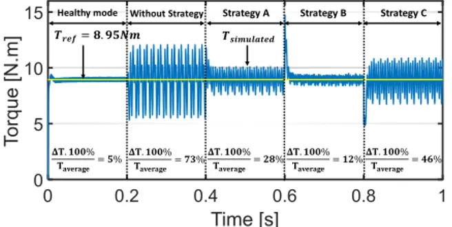
Torque in terms of time in healthy and faulty modes is shown in Fig. 8. Healthy mode has torque ripples of 5%. In faulty mode, without new current references, torque pulsatio-
5
(a) (b) (c)
Fig. 4. Healthy mode currents in natural frame (a), α-β frames (b), d-q frames (c)
(a) (b) (c)
Fig. 5. Faulty mode currents with strategy A in natural frame (a), α-β frames (b), d-q frames (c)
(a) (b) (c)
Fig. 6. Faulty mode currents with strategy B in natural frame (a), α-β frames (b), d-q frames (c)
(a) (b) (c)
Fig. 7. Faulty mode currents with strategy C in natural frame (a), α-β frames (b), d-q frames (c) -ns increase to 73%. Strategy B has the smallest torque ripples
of 12% among three strategies (28 and 46% for strategies A and C respectively). Indeed, the low frequency of time-variant current i enables the simulated values to track their references easily by PI controller as shown in Fig. 10. However, the simulated zero-sequence current i contains
high-frequency components due to the PWM switching [16, 17]. On the contrary, there are bigger control errors in strategy A (Fig. 9) and especially in strategy C (Fig. 11) due to high-frequency d2-q2 currents as discussed in the previous sections,
6 Fig. 8. Torque in terms of time at 30rad/s in healthy and faulty modes
with different strategies A, B and C
Fig. 9. Control of time-variant d2-q2 currents ( , )in Strategy A at 30rad/s
Fig. 10. Control of time-variant current ( ) in strategy B at 30rad/s
Fig. 11. Control of time-variant d2-q2 currents ( , )in strategy C at 30rad/s
V. CONCLUSIONS
In this paper, two fault-tolerant control strategies for field-oriented control of 7-phase non-sinusoidal machines have been proposed. One phase open-circuit fault has been considered. The proposed strategies aim at determining the new current references for post-fault operations to preserve the rotational MMF as in healthy mode. The proposed strategies are compared with an existing strategy in terms of joule losses, maximal RMS and peak currents, maximal peak voltages and controllability with PI controllers. The newly proposed strategy A gives the best results in terms of joule
losses and RMS currents while strategy B is the best for the control aspect with a simple controller such as PI.
REFERENCES
[1] E. Levi, "Multiphase Electric Machines for Variable-Speed Applications," IEEE Transactions on Industrial Electronics, vol. 55, no. 5, pp. 1893-1909, 2008.
[2] M. J. Duran and F. Barrero, "Recent Advances in the Design, Modeling, and Control of Multiphase Machines Part II," IEEE
Transactions on Industrial Electronics, vol. 63, no. 1, pp. 459-468,
2016.
[3] F. Barrero and M. J. Duran, "Recent Advances in the Design, Modeling, and Control of Multiphase Machines Part I," IEEE
Transactions on Industrial Electronics, vol. 63, no. 1, pp. 449-458,
2016.
[4] W. Jiabin, K. Atallah, and D. Howe, "Optimal torque control of fault-tolerant permanent magnet brushless machines," IEEE Transactions
on Magnetics, vol. 39, no. 5, pp. 2962-2964, 2003.
[5] S. Dwari and L. Parsa, "Open-circuit fault tolerant control of five-phase permanent magnet motors with third-harmonic back-EMF," in
2008 34th Annual Conference of IEEE Industrial Electronics, Orlando,
FL, USA, 2008, pp. 3114-3119.
[6] S. Dwari and L. Parsa, "Fault-Tolerant Control of Five-Phase Permanent-Magnet Motors With Trapezoidal Back EMF," IEEE
Transactions on Industrial Electronics, vol. 58, no. 2, pp. 476-485,
2011.
[7] X. Kestelyn and E. Semail, "A Vectorial Approach for Generation of Optimal Current References for Multiphase Permanent-Magnet Synchronous Machines in Real Time," IEEE Transactions on
Industrial Electronics, vol. 58, no. 11, pp. 5057-5065, 2011.
[8] F. Jen-Ren and T. A. Lipo, "Disturbance-free operation of a multiphase current-regulated motor drive with an opened phase,"
IEEE Transactions on Industry Applications, vol. 30, no. 5, pp.
1267-1274, 1994.
[9] F. Locment, E. Semail, and X. Kestelyn, "Vectorial Approach-Based Control of a Seven-Phase Axial Flux Machine Designed for Fault Operation," IEEE Transactions on Industrial Electronics, vol. 55, no. 10, pp. 3682-3691, 2008.
[10] R. Hyung-Min, K. Ji-Woong, and S. Seung-Ki, "Synchronous-frame current control of multiphase synchronous motor under asymmetric fault condition due to open phases," IEEE Transactions on Industry
Applications, vol. 42, no. 4, pp. 1062-1070, 2006.
[11] H. Guzmán, M. J. Durán, and F. Barrero, "A comprehensive fault analysis of a five-phase induction motor drive with an open phase," in
2012 15th International Power Electronics and Motion Control Conference (EPE/PEMC), Novi Sad, Serbia, 2012, pp.
LS5b.3-1-LS5b.3-6.
[12] D. T. Vu, N. K. Nguyen, E. Semail, and T. J. Dos Santos Moraes, "Torque optimization of seven phase BLDC machines in normal and degraded modes with constraints on current and voltage," in PEMD
2018, the 9th International Conference on Power Electronics, Machines and Drives, Liverpool, United Kingdom, 2018.
[13] D. T. Vu, N. K. Nguyen, E. Semail, and T. J. dos Santos Moraes, "Control Strategies for Non-sinusoidal Multiphase PMSM Drives in Faulty Modes under Constraints on Copper Losses and Peak Phase Voltage," IET Electric Power Applications, p. 11, 5/2019.
[14] E. Semail, X. Kestelyn, and A. Bouscayrol, "Right harmonic spectrum for the back-electromotive force of an n-phase synchronous motor," in Conference Record of the 2004 IEEE Industry Applications
Conference, 2004. 39th IAS Annual Meeting., Seattle, WA, USA,
2004, vol. 1, pp. 1-78.
[15] J. Gong, H. Zahr, E. Semail, M. Trabelsi, B. Aslan, and F. Scuiller, "Design Considerations of Five-Phase Machine With Double p/3p Polarity," IEEE Transactions on Energy Conversion, vol. 34, no. 1, pp. 12-24, 2019.
[16] T. J. D. S. Moraes, M. Trabelsi, H. Zahr, and E. Semail, "Homopolar Current's Copper Losses Analysis for Different Modulations in Open-End Winding Five-Phase Drives," in 2018 XIII International
Conference on Electrical Machines (ICEM), Alexandroupoli, Greece,
2018, pp. 1538-1544.
[17] P. Sandulescu et al., "FPGA implementation of a general Space Vector approach on a 6-leg voltage source inverter," in IECON 2011
- 37th Annual Conference of the IEEE Industrial Electronics Society,
Melbourne, VIC, Australia, 2011, pp. 3482-3487.
0 0.2 0.4 0.6 0.8 1
0 5 10
15 Healthy mode Without Strategy Strategy A Strategy B Strategy C
. %
= % . %= % . %= % . %= % . %= %
= .
_ _