an author's
https://oatao.univ-toulouse.fr/26918
https://doi.org/10.1016/j.ijnonlinmec.2020.103545
Guimarães, Thiago A.M. and Sanches, Leonardo and Marques, Flávio D. Nonlinear supersonic post-flutter motion of
panels with adjacent bays and thermal effects. (2020) International Journal of Non-Linear Mechanics, 125.
Nonlinear supersonic post-flutter motion of panels with adjacent bays and
thermal effects
Thiago A.M. Guimarães
a, Leonardo Sanches
b, Flávio D. Marques
c,∗ aSchool of Mechanical Engineering, Federal University of Uberlândia – UFU, BrazilbUniversité de Toulouse, ICA, CNRS, ISAE-Supaero, Toulouse, France
cSão Carlos School of Engineering, University of São Paulo, São Carlos, SP, Brazil
Keywords: Aeroelasticity Supersonic panel flutter Multi-bay panel flutter Thermo-buckling loading Nonlinear dynamics Rayleigh–Ritz method
A B S T R A C T
Aerospace vehicle structures in the supersonic regime flight have their outer skin subjected to unsteady aerodynamic and thermal loading, which may lead to aeroelastic instability. Typical aerospace structures are built as multiple adjacent panels, the so-called multi-bay configuration, but early efforts to predict the supersonic flutter were based on a single panel arrangement. This work evaluates the aeroelastic behavior of supersonic multi-bay fluttering panels under thermal effects, aiming to improve the understanding of adjacent panels interaction in the nonlinear regime. The aeroelastic model is established by using the first-order quasi-steady piston theory in conjunction with isotropic panel model using the von Kármán’s assumptions to account for geometrical nonlinearities. The Newmark time-integration method is used to evaluate the resulting equations of motion. The Hopf bifurcation behavior that determines the flutter onset, thermo-buckling loading, phase portrait plots, and bifurcation diagrams for two adjacent panels are presented. The numerical results show the detrimental aspect of thermal loading in the aeroelastic behavior of fluttering panels, and the new findings corroborate with some recent studies that highlight the difference in the nonlinear flutter behavior between a single panel and multi-bay panels. Moreover, the existence of limit cycle oscillations amplitude jumps from a certain level of flow dynamic pressure is also observed. The multi-bay panels configuration also shows the anticipation of the buckled to the limit cycle oscillation solutions, when compared with a single panel analysis. Results indicate that simplified single bay panel assumptions can underestimate the post-flutter oscillations amplitudes of the adjacent bay. Such dynamic behavior may lead to a negative impact on aircraft structural design and fatigue life estimation.
1. Introduction
The dynamic instability of plates and shells under the effects of supersonic flow has been investigated since the 1950s. The so-called panel flutter is an aeroelastic problem occurring in parts of the aircraft external skin, leading to fatigue damages and possible collapse of the structure [1–3]. Most of the earlier panel flutter analyses were per-formed through numerical simulations with few validations, as experi-mental data were not easily available. Moreover, the flutter problem was mostly predicted admitting a single panel [4,5]. Real aircraft structures are assembled in such way that in practice one has adjacent panels arrangement, that is, multi-bay panels.
Recently, the multi-bay panel flutter has been revisited by Pacheco and co-workers [6–8], being the first to present a nonlinear analysis based on the finite element method. The multi-bay panel flutter was initially investigated in the 1960s by Dowell [9,10], Rodden [11], and Lock and Farkas [12] using linear structure modeling. The conclu-sions from these pioneering research show that the flutter boundary
∗ Corresponding author.
E-mail addresses: [email protected](T.A.M. Guimarães),[email protected](L. Sanches),[email protected](F.D. Marques).
was determined by the single panel solution alone. The boundary is only significantly affected when a large number of bays is taken into account.
The first nonlinear analysis of the multi-bay panel flutter was pre-sented by Pacheco et al. [6]. They investigated several arrangements of two- and three-bay with simply supported boundary conditions between the adjacent panels. The nonlinear equation of motion was modeled with a high-order finite element formulation and von Kármán strain–displacement relations for thin isotropic plates jointly with un-steady aerodynamics given by the first-order piston model. The critical flutter dynamic pressure coincides with the linear prediction, but the post-flutter mechanism is affected by adjacent panels coupling. As a consequence, the evolution in dynamic pressure leads to amplitude jumps in the limit cycle oscillations. Moreover, coexisting limit cycles sensitive to the initial conditions were also observed in the region of the amplitude jumps.
Pacheco et al. [7] solved the nonlinear supersonic panel flutter of multi-bay arrangements using a nonlinear beam between the adjacent bays, which works as an elastic stringer. The finite element method was employed considering the Mindlin plate model for the panel and the Timoshenko beam theory for the stiffeners. Geometrical nonlin-earity was included in both plate and beam through the von Kármán strain–displacement relations. The unsteady aerodynamic loading was calculated with the first-order piston theory. The equations of motion were solved in the time domain with the Newmark integration ap-proach. The results demonstrate that the multi-bay problem follows similar flutter mechanisms for simply supported and stiffened adjacent panels. Moreover, jumps on the limit cycle amplitude are also detected in the post-flutter regime. The stiffener cross-sectional geometry plays an important role in the post-flutter mechanism and can be designed to diminish oscillations amplitudes. Pacheco et al. [8] also performed an energy approach to the analysis of the multi-bay panel flutter. They investigated how mechanical energy is distributed among the multi-bays and the elastic stiffener.
Most of the works mentioned before were based on structural dynamics modeling using the finite element method. Despite all the advantages of the finite element approaches, a significant disadvan-tage relies on high computational cost when time integration of the resulting nonlinear equations of motion is necessary. An alternative form of overcoming the computational cost can be achieved with the application of the Rayleigh–Ritz method. The Rayleigh–Ritz method is a semi-analytical approach that consists of assuming admissible functions for the three displacements fields of a plate, forming the approximate solutions for the respective set of nonlinear partial derivative equations. The method allows the evaluation in wide range geometry of linear and nonlinear structures with computational efficiency, as the overall order of the nonlinear aeroelastic system is usually lower than the finite element model counterparts.
To the best of the author’s knowledge, a nonlinear aeroelastic analysis of multi-bay panel flutter with thermal buckling has not been available in the literature. Indeed, as shown for a single panel, the operational temperature variation leads to mechanical constraints on the structure that may affect its dynamics significantly [4]. Moreover, the application of the Rayleigh–Ritz approach to the multi-bay prob-lem is also a novelty that brings the advantage of faster numerical integration of the aeroelastic equations regarding supersonic flutter analyses. Recently, Guimarães et al. [13] verified the applicability and brought forward the computational performance advantages of the semi-analytical Ritz-type model in the analysis of multi-bay composite laminates supersonic panel flutter. Guimarães et al. [13] compared the Rayleigh–Ritz (RR) with the finite element method (FEM) revealing that the RR approach solved the two-bay supersonic flutter problem with no thermal effects in approximately a fifth of the time used for FEM. The analysis also included the post-flutter jump prediction capabilities of the RR approach regarding the number of modes and adopted boundary conditions.
To fill the gaps of the nonlinear supersonic panel flutter analy-sis of multiple adjacent bay assemble including thermal loading, the Rayleigh–Ritz method is used to analyze an isotropic thin panel sub-jected to supersonic flow. The thermal effects are incorporated into the model through the in-plane normal and shear loading. The connection between two adjacent bays is achieved employing a penalty approach, in which the assembly relations compatibility is guaranteed, which results in the continuous membrane and bending loads from one panel to another. The unsteady aerodynamic loading is modeled with the first-order piston theory and incorporated to the aeroelastic equations. The Newmark method is used to assess the time integration of the aeroelastic equations of motion. The next sections present the Rayleigh– Ritz-type model for the multi-bay panel flutter analysis, followed by a model verification using previous results encountered in the literature. The multi-bay panel flutter problem is addressed for the case of two-bay panels and thermal loading. The effects of temperature changes on the limit cycle amplitude jumps are discussed.
Fig. 1. Illustration of a rectangular plate model used in the supersonic flutter analysis.
2. Nonlinear aeroelastic model
Consider a rectangular plate of dimensions 𝑎 × 𝑏 separating a cavity with stagnated air and a supersonic flow field as depicted inFig. 1. The edges of the plate are simply supported, allowing only rotations and no translation motion. The plate is modeled by assuming the plane stress state with displacements (𝑢, 𝑣, 𝑤), respectively in the (𝑥, 𝑦, 𝑧)-directions. Under the Kirchhoff hypothesis, which assumes that transverse and shear strains are zero and the transverse displacement (𝑤) being in-dependent of the transverse coordinate, 𝑧, the displacements (𝑢, 𝑣, 𝑤) are defined as:
𝑢(𝑥, 𝑦, 𝑧, 𝑡) = 𝑢0(𝑥, 𝑦, 𝑡) − 𝑧 𝜕𝑤0(𝑥, 𝑦, 𝑡) 𝜕𝑥 , 𝑣(𝑥, 𝑦, 𝑧, 𝑡) = 𝑣0(𝑥, 𝑦, 𝑡) − 𝑧 𝜕𝑤0(𝑥, 𝑦, 𝑡) 𝜕𝑦 , 𝑤(𝑥, 𝑦, 𝑧, 𝑡) = 𝑤0(𝑥, 𝑦, 𝑡) , (1)
where 𝑢0(𝑥, 𝑦, 𝑡), 𝑣0(𝑥, 𝑦, 𝑡) and 𝑤0(𝑥, 𝑦, 𝑡) are the mid-plane
displace-ments.
The strain–displacement relations based on the von Kármán’s non-linear relation small strains and moderately large rotations [14] is used, resulting in the following vector:
𝝐= ⎧ ⎪ ⎨ ⎪ ⎩ 𝜖𝑥 𝜖𝑦 𝛾𝑥𝑦 ⎫ ⎪ ⎬ ⎪ ⎭ = ⎧ ⎪ ⎪ ⎨ ⎪ ⎪ ⎩ 𝜕𝑢0(𝑥,𝑦,𝑡) 𝜕𝑥 − 𝑧 𝜕2𝑤 0(𝑥,𝑦,𝑡) 𝜕𝑥2 + 1 2 ( 𝜕𝑤0(𝑥,𝑦,𝑡) 𝜕𝑥 )2 𝜕𝑣0(𝑥,𝑦,𝑡) 𝜕𝑦 − 𝑧 𝜕2𝑤 0(𝑥,𝑦,𝑡) 𝜕𝑦2 + 1 2 (𝜕𝑤 0(𝑥,𝑦,𝑡) 𝜕𝑦 )2 (𝜕𝑢 0(𝑥,𝑦,𝑡) 𝜕𝑥 + 𝜕𝑣0(𝑥,𝑦,𝑡) 𝜕𝑦 ) − 2𝑧𝜕2𝑤0(𝑥,𝑦,𝑡) 𝜕𝑥𝜕𝑦 + 𝜕𝑤0(𝑥,𝑦,𝑡) 𝜕𝑥 𝜕𝑤0(𝑥,𝑦,𝑡) 𝜕𝑦 ⎫ ⎪ ⎪ ⎬ ⎪ ⎪ ⎭ , (2) where 𝑢0(𝑥, 𝑦, 𝑡)and 𝑣0(𝑥, 𝑦, 𝑡) are the membrane displacement in the
mid-plane, and 𝑤0(𝑥, 𝑦, 𝑡) are out of plane mid-plane displacement,
which can be conveniently split into linear terms as:
𝝐𝐿= ⎧ ⎪ ⎨ ⎪ ⎩ 𝜖𝐿 𝑥 𝜖𝐿𝑦 𝛾𝐿 𝑥𝑦 ⎫ ⎪ ⎬ ⎪ ⎭ = ⎧ ⎪ ⎪ ⎨ ⎪ ⎪ ⎩ 𝜕𝑢0(𝑥,𝑦,𝑡) 𝜕𝑥 𝜕𝑣0(𝑥,𝑦,𝑡) 𝜕𝑦 (𝜕𝑢 0(𝑥,𝑦,𝑡) 𝜕𝑥 + 𝜕𝑣0(𝑥,𝑦,𝑡) 𝜕𝑦 ) ⎫ ⎪ ⎪ ⎬ ⎪ ⎪ ⎭ , (3) and 𝜿= ⎧ ⎪ ⎨ ⎪ ⎩ 𝜅𝑥 𝜅𝑦 𝜅𝑥𝑦 ⎫ ⎪ ⎬ ⎪ ⎭ = ⎧ ⎪ ⎪ ⎨ ⎪ ⎪ ⎩ 𝜕2𝑤 0(𝑥,𝑦,𝑡) 𝜕𝑥2 𝜕2𝑤0(𝑥,𝑦,𝑡) 𝜕𝑦2 2𝜕2𝑤0(𝑥,𝑦,𝑡) 𝜕𝑥𝜕𝑦 ⎫ ⎪ ⎪ ⎬ ⎪ ⎪ ⎭ , (4)
and nonlinear one as:
𝝐𝑁 𝐿= ⎧ ⎪ ⎨ ⎪ ⎩ 𝜖𝑁 𝐿 𝑥 𝜖𝑁 𝐿𝑦 𝛾𝑁 𝐿 𝑥𝑦 ⎫ ⎪ ⎬ ⎪ ⎭ = ⎧ ⎪ ⎪ ⎨ ⎪ ⎪ ⎩ 1 2 (𝜕𝑤 0(𝑥,𝑦,𝑡) 𝜕𝑥 )2 1 2 (𝜕𝑤 0(𝑥,𝑦,𝑡) 𝜕𝑦 )2 𝜕𝑤0(𝑥,𝑦,𝑡) 𝜕𝑥 𝜕𝑤0(𝑥,𝑦,𝑡) 𝜕𝑦 ⎫ ⎪ ⎪ ⎬ ⎪ ⎪ ⎭ . (5)
Under the assumptions of the Classical Plate Theory [14], and con-sidering a plate of isotropic material, the following relation between the internal forces and moments with the in-plane strains and curvatures are obtained: { 𝑸 𝑴 } = [ 𝑨 𝟎 𝟎 𝑫 ] { 𝝐𝐿+ 𝝐𝑁 𝐿 𝜿 } , (6)
in which, 𝑴 is the vector of moments and 𝑸 is the vector of forces. Moreover, the membrane and bending terms are given by the matrices 𝑨and 𝑫 and they are expressed, for isotropic materials, as:
𝑨= 𝐸ℎ 1 − 𝜈2 ⎡ ⎢ ⎢ ⎣ 1 𝜈 0 𝜈 1 0 0 0 1 2(1 − 𝜈) ⎤ ⎥ ⎥ ⎦ , (7) and 𝑫= ℎ 2 12𝑨 , (8)
where 𝐸 is the modulus of Young of the plate, 𝜈 is the Poison’s coefficient and ℎ the plate thickness.
The strain energy of the isotropic plate may be expressed by:
𝑈= 1 2∫ 𝑎 0 ∫ 𝑏 0 { 𝝐𝐿}𝑇 𝑨𝝐𝐿𝑑𝑥𝑑𝑦 + 1 2∫ 𝑎 0 ∫ 𝑏 0 { 𝜿𝐿}𝑇 𝑫𝜿𝐿𝑑𝑥𝑑𝑦+ + 1 2∫ 𝑎 0 ∫ 𝑏 0 { 𝝐𝐿}𝑇 𝑨𝝐𝑁 𝐿𝑑𝑥𝑑𝑦 + 1 2∫ 𝑎 0 ∫ 𝑏 0 { 𝝐𝑁 𝐿}𝑇 𝑨𝝐𝐿𝑑𝑥𝑑𝑦+ + 1 2∫ 𝑎 0 ∫ 𝑏 0 { 𝝐𝑁 𝐿}𝑇𝑨𝝐𝑁 𝐿𝑑𝑥𝑑𝑦 . (9)
Regarding the kinetic energy, it is used the hypotheses of the Kirchhoff theory [15], which is adequate for thin plates:
𝑇=1 2∫ ℎ 0 ∫ 𝑏 0 ∫ 𝑎 0 𝜌0[̇𝑢2+ ̇𝑣2+ ̇𝑤2]𝑑𝑥 𝑑𝑦 𝑑𝑧 , (10) where 𝜌0is the plate material density.
The thermal effects are incorporated in the model throughout in-plane normal and shear loads (𝑁𝑥𝑥, 𝑁𝑦𝑦, 𝑁𝑥𝑦) defined as:
𝑵𝛥𝑇 =
[
𝑁𝑥𝑥 𝑁𝑦𝑦 𝑁𝑥𝑦]𝑇 = 𝑨𝛥𝑇[𝛼𝑥 𝛼𝑦 𝛼𝑥𝑦]𝑇 , (11)
where[𝛼𝑥 𝛼𝑦 𝛼𝑥𝑦]𝑇 are the thermal expansion coefficients and 𝛥𝑇 is represents the temperature variation.
The corresponding potential energy due to thermal-induced loads is: 𝑈𝛥𝑇 = −1 2∫ 𝑎 0 ∫ 𝑏 0 [ 𝑁𝑥𝑥(𝜕𝑤 𝜕𝑥 )2 + 𝑁𝑦𝑦 ( 𝜕𝑤 𝜕𝑦 )2 + 2𝑁𝑥𝑦 𝜕𝑤 𝜕𝑥 𝜕𝑤 𝜕𝑦 ] 𝑑𝑥𝑑𝑦 . (12) The unsteady aerodynamic pressure distribution over the panel is modeled with the first-order piston theory [16], which performs satis-factorily within the range of Mach admitted in this investigation [17, 18], namely, 𝛥𝑃(𝑥, 𝑦, 𝑡) =√2𝑞𝑑𝑦𝑛 𝑀2− 1 [( 𝜕𝑤 𝜕𝑥 + 𝑀2− 2 𝑀2− 1 1 𝑈∞ 𝜕𝑤 𝜕𝑡 )] , (13)
where 𝑞𝑑𝑦𝑛, 𝑀 and 𝑈∞ are the dynamic pressure, Mach number, and
flow velocity, respectively.
Then, the variation of the virtual work done by the aerodynamic loading is attained by a complicated nonlinear dependence on the surface motion as demonstrated in Amabili and Breslavsky [19] and Amabili [20]. Here, an approximation with respect to the normal surface displacement is assumed and represented as,
𝛿𝑊 = ∫ 𝑎 0 ∫ 𝑏 0 𝛥𝑃(𝑥, 𝑦, 𝑡) 𝛿𝑤𝑑𝑥𝑑𝑦 . (14)
For the approximate solution of a simply supported immovable edges panel, the displacement field are evaluated using a set of Ritz functions as generalized coordinates [21], that is,
Fig. 2. Simply supported multi-bay configuration assembly.
Fig. 3. Flutter onset point and amplitude convergence study with respect to the dynamic pressure. 𝑢0(𝑥, 𝑦, 𝑡) = 𝑀𝑢 ∑ 𝑚=0 𝑁𝑢 ∑ 𝑛=0 𝑞𝑢𝑚𝑛(𝑡) sin ( 𝑚𝑥 𝜋 𝑎 ) sin ( 𝑛𝑦 𝜋 𝑏 ) = 𝑀𝑢 ∑ 𝑚=0 𝑁𝑢 ∑ 𝑛=0 𝑆𝑢 𝑚𝑛(𝑥, 𝑦) 𝑞𝑢𝑚𝑛(𝑡) , (15) 𝑣0(𝑥, 𝑦, 𝑡) = 𝑀𝑣 ∑ 𝑚=0 𝑁𝑣 ∑ 𝑛=0 𝑞𝑣𝑚𝑛(𝑡) sin(𝑚𝑥 𝜋 𝑎 ) sin(𝑛𝑦 𝜋 𝑏 ) = 𝑀𝑣 ∑ 𝑚=0 𝑁𝑣 ∑ 𝑛=0 𝑆𝑣𝑚𝑛(𝑥, 𝑦) 𝑞𝑣𝑚𝑛(𝑡) , (16) 𝑤0(𝑥, 𝑦, 𝑡) = 𝑀𝑤 ∑ 𝑚=0 𝑁𝑤 ∑ 𝑛=0 𝑞𝑤𝑚𝑛(𝑡) sin ( 𝑚𝑥 𝜋 𝑎 ) sin ( 𝑛𝑦 𝜋 𝑏 ) = 𝑀𝑤 ∑ 𝑚=0 𝑁𝑤 ∑ 𝑛=0 𝑆𝑤 𝑚𝑛(𝑥, 𝑦) 𝑞𝑤𝑚𝑛(𝑡) , (17) where 𝑞(𝑖)𝑚𝑛and 𝑆 (𝑖)
𝑚𝑛, (𝑖) = [𝑢, 𝑣, 𝑤]represent the generalized
coordi-nate and the assumed mode shape function used for the Rayleigh–Ritz expansion of the displacement fields along the directions 𝑥, 𝑦, and 𝑧, respectively.
Eqs.(15)to(17)can be summarized in matrix notation as: ⎧ ⎪ ⎨ ⎪ ⎩ 𝑢0(𝑥, 𝑦, 𝑡) 𝑣0(𝑥, 𝑦, 𝑡) 𝑤0(𝑥, 𝑦, 𝑡) ⎫ ⎪ ⎬ ⎪ ⎭ = ⎡ ⎢ ⎢ ⎣ 𝑺𝑇 𝑢 0 0 0 𝑺𝑇𝑣 0 0 0 𝑺𝑇𝑤 ⎤ ⎥ ⎥ ⎦ ⎧ ⎪ ⎨ ⎪ ⎩ 𝒒𝒖 𝒒𝒗 𝒒𝒘 ⎫ ⎪ ⎬ ⎪ ⎭ = 𝑺𝑢,𝑣,𝑤𝒒𝑠𝑝 , (18)
where 𝒒𝒖, 𝒒𝒗 and 𝒒𝒘 are vectors containing the 𝑀(𝑖)× 𝑁(𝑖),for 𝑖 =
[𝑢, 𝑣, 𝑤] generalized coordinates, respectively. Similarly, and 𝑺𝑢, 𝑺𝑣,
and 𝑺𝑤 are vectors containing the assumed shape functions along 𝑥,
𝑦and 𝑧 directions, respectively. The vector 𝒒𝑠𝑝 contains the general-ized coordinates for modeling the nonlinear aeroelastic problem with thermal constraints for a single panel problem.
Nonetheless, the present paper aims extending the analysis for multi-bay panel configurations.Fig. 2illustrates the multi-bay problem, where the simply supported immovable edges boundary condition is assumed for all edges and in between the bays.
Fig. 4. Verification of limit cycle amplitudes for a simple supported panel (𝑎∕𝑏 = 1) considering 𝜇∕𝑀 = 0.1.
To model a panel formed by two adjacent plates with the Rayleigh– Ritz method, each 𝑖th plate is modeled individually with respect to a global referential system and a penalty approach as described by Castro and Donadon [22] is considered. The model assembly must guarantee the following compatibility relations represented as:
(𝑢, 𝑣, 𝑤)𝐿𝐻 𝑆= (𝑢, 𝑣, 𝑤)𝑅𝐻 𝑆 , (19) (𝑑𝑤 𝑑𝑥 ) 𝐿𝐻 𝑆= (𝑑𝑤 𝑑𝑥 ) 𝑅𝐻 𝑆 , (20)
where the subscripts 𝐿𝐻𝑆 and 𝑅𝐻𝑆 denote left-hand side and right-hand side, respectively, and the penalty energy terms for each 𝑖th connection line for each bay, defined as:
𝑈 𝑝𝑖= ∫ 𝑏 0 ( 𝑑𝑤(𝑖𝑎, 𝑦)𝐿𝐻 𝑆𝑖 𝑑𝑥 − 𝑑𝑤(𝑖𝑎, 𝑦)𝑅𝐻 𝑆𝑖 𝑑𝑥 )2 𝑘𝑟𝑖𝑑𝑦 , (21)
whereas 𝑘𝑟𝑖is the stiffness penalty calculated considering continuous
membrane and bending loads from one bay to another, that is,
𝑘𝑟𝑖= 4𝐷 𝐿𝐻 𝑆𝑖 11 𝐷 𝑅𝐻 𝑆𝑖 11 (𝐷𝐿𝐻 𝑆𝑖 11 + 𝐷 𝑅𝐻 𝑆𝑖 11 )(ℎ𝐿𝐻 𝑆𝑖+ ℎ𝑅𝐻 𝑆𝑖) , (22)
where 𝐷11are the first term of matrix 𝑫 (cf. Eq.(8)).
The aeroelastic equations of motion are then derived from the Lagrange’s formulation, that is,
𝑑 𝑑𝑡 ( 𝜕𝑇 𝜕 ̇𝒒 ) −𝜕𝑇 𝜕𝒒 + 𝜕𝑈 𝜕𝒒 = 𝜕(𝛿𝑊 ) 𝜕(𝛿𝒒) , (23) where 𝒒 = [𝒒𝑠𝑝,1, 𝒒𝑠𝑝,2 ]𝑇
is the vector containing the generalized coordinates of the first and second single plates, respectively.
Fig. 6. Limit cycle amplitudes for a simple supported panel (𝑎∕𝑏 = 1) considering 𝜇∕𝑀 = 0.1, 𝜆 = 800, and 𝛥𝑇 ∕𝛥𝑇𝑏𝑢𝑐𝑘 = 1.0 and compared with results from Zhou
et al. [23].
Fig. 7. Selected points for the multi-bay panel aeroelastic evaluation.
The aeroelastic equations of motion is obtained by combining the expressions of the potential energy, kinetic energy, and the work ex-erted by the aerodynamic loading to the Lagrange’s equations. After a convenient treatment to the aeroelastic equations of motion, the fol-lowing set of coupled, second-order normalized differential equations is obtained (details on each matrix is presented in Appendix), that is,
𝑴 ̈𝒒(𝑡)+𝑔𝑪 ̇𝒒 (𝑡)+[𝜆𝑲𝑎+ 𝛥𝑇 𝑲𝐺+ 𝑲 + 𝑲𝑝𝑖+ 𝑲𝑁 𝐿1(𝑢, 𝑣, 𝑤) + 𝑲𝑁 𝐿2(𝑤) ]
𝒒(𝑡) = 𝟎 ,
(24) where 𝒒(𝑡) is the generalized coordinate vector, 𝑴 is the mass matrix, 𝑲𝑎is the aerodynamic stiffness matrix, 𝜆 is the dimensionless dynamic
Fig. 8. Comparison of limit cycle amplitudes between a single bay and multi-bay configuration, considering 𝜇∕𝑀 = 0.1 and simple supported panels.
pressure, denoted as
𝜆= 2𝑞𝑑𝑦𝑛𝑎
3
𝐷√𝑀2− 1
, (25)
where 𝐷 = (𝐸ℎ3)∕[12(1 − 𝜈2)]is the plate bending stiffness parameter,
𝛥𝑇𝑲𝐺is the geometric stiffness matrix taking into account the thermal
effect, 𝑲 is the structural stiffness matrix, 𝑲𝑝
𝑖 is the penalty stiffness at the 𝑖th connection line between adjacent bays, 𝑲𝑁 𝐿1 is the first
order nonlinear structural stiffness, 𝑲𝑁 𝐿2is the second order nonlinear
structural stiffness, and 𝑔𝑪 is the aerodynamic damping matrix, where
𝑔is the dimensionless parameter [5] associated with 𝜕𝑤
𝜕𝑡 from Eq.(13), 𝑔= √ 𝜆𝜇 √ 𝑀2− 1 ( 𝑀2− 2 𝑀2− 1 ) ≃√𝜆𝜇∕𝑀 , (26)
along with 𝜇 =(𝜌air∕𝜌𝑚
)
(𝑎∕ℎ)is the so-called mass ratio. Although the approximation given in Eq.(26)admits flow regimes at higher Mach numbers, for 𝑀 < 3 the flutter computation may not attain the desired
precision [24,25
the approximation of 𝑔 provides adequate qualitative outcomes. The nonlinear system represented in Eq.(24)was assessed consider-ing sinusoidal functions as assumed modes in 𝑥-direction and two in the
𝑦-direction. The set of equations of motion is solved numerically in time using the Newmark method, similar as employed by Chen and Sun [26] and modified by Pacheco et al. [8], which takes into account damping effects. Since the aeroelastic equation of motion is homogeneous, the initial condition is considered a static deformed shape resulting from the application of a uniformly distributed pressure. From simulated time responses, bifurcation diagrams are also determined from exerting the time histories and subsequent extraction of the amplitude attained in limit cycle oscillation regime. The time integration of the equations of motion is performed adopting a small pressure distribution as initial condition.
The thermal buckling load can be obtained from the following generalized eigenvalue problem from neutral static equilibrium crite-rion [22],
(
𝛥𝑇𝑲𝐺+ 𝑲 + 𝑲𝑝𝑖 )
𝒒(𝑡) = 𝟎 . (27)
The non-trivial solutions of Eq.(27)reveal eigenvalues 𝛥𝑇 , where the lowest one is the so-called critical buckling temperature variation, that is, 𝛥𝑇𝑏𝑢𝑐𝑘.
3. Model verification
The mathematical model was initially checked with respect to the number of assumed modes that promotes convergence of the system’s response. Based on the geometry giving inFig. 1, the number of modes was varied in such way that two modes in y-direction were kept fix.Fig. 3shows how the solutions for flutter dynamic pressure and the post-flutter limit cycle oscillations evolve with 𝜆. All cases were based on the parameters given by Dowell [27]. The convergence study demonstrates that solutions start to saturate when a total of 10 modes are considered (5 modes in 𝑥-direction and 2 in 𝑦-direction).
Earlier results of panel flutter prediction under the effects of thermal loading were presented by Dowell [4] and Mei et al. [5]. The critical flutter condition is reached at a dynamic pressure value from which the panel oscillations stop presenting damped behavior. With the rise of the dynamic pressure value from the flutter condition one, an amplitude growth of the limit cycle oscillations is observed. This oscillatory regime leads to a Hopf bifurcation condition because of the structural geometric nonlinearity [28].
Here, the present aeroelastic model is verified under the same conditions of results established in the literature. Dowell [4] and Mei
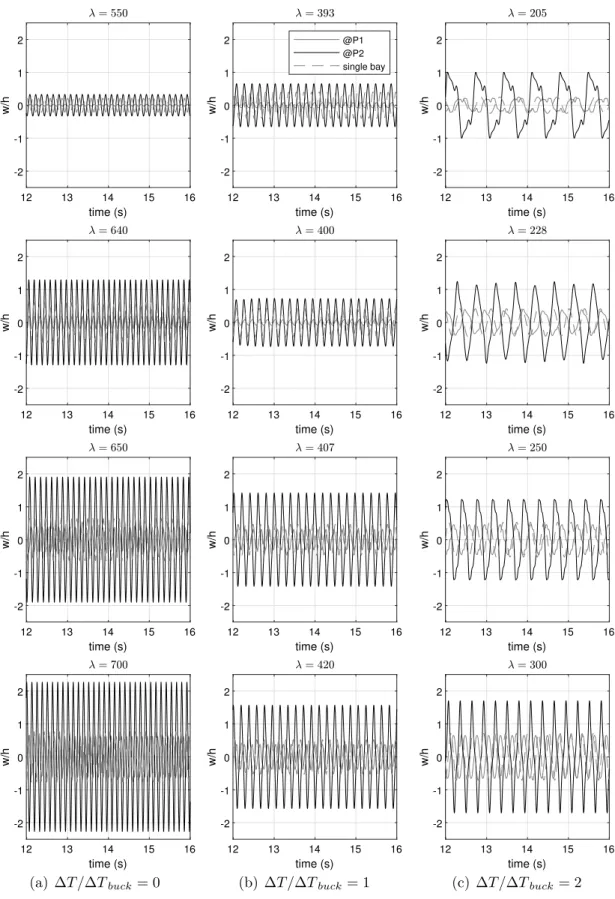
Fig. 10. Time histories for different 𝛥𝑇 ∕𝛥𝑇𝑏𝑢𝑐𝑘and 𝜆 values for the single and multi-bay panels.
et al. [5] used the finite element method to model a simply supported isotropic squared plate with 𝑎 = 2.43 m, ℎ∕𝑎 = 0.01, and the material’s mechanical properties are 𝐸 = 70 GPa for the Young’s module, and
𝜈 = 0.25for the Poison’s coefficient. Simulations were performed for Mach numbers larger than√2to ensure the piston theory assumptions, thereby fixing the range for the dimensionless parameters. It is worth
mentioning that simplified damping parameter as given in Eq. (26) yields some limitation to the results for 𝑀 < 3. Detailed discussion on this issue is provided by Vedeneev and co-workers [24,25,29]. Here, the model simplification has been considered adequate as it provides good agreement with the results by Dowell [4], as follows. Moreover, a ratio of 𝜇∕𝑀 = 0.1 with temperature variation 𝛥𝑇 ∕𝛥𝑇𝑏𝑢𝑐𝑘 = 0, 1,
Fig. 11. Phase portrait for different 𝛥𝑇 ∕𝛥𝑇𝑏𝑢𝑐𝑘and 𝜆 values for the single and multi-bay panels.
and 2 were proposed, where the buckling in-plane loads in still air is computed 𝑁𝑥𝑥 = 𝑁𝑦𝑦 = 300, 770 Nm, and the thermal expansion
coefficients 𝜶 = [1 1 0]𝑇. Fig. 4 compares the evolution of the
limit cycle oscillations (LCO) amplitudes as a function of different operational conditions (i.e., flutter dynamic pressure and thermal con-ditions) assessed by Dowell [4] with those obtained with the present model. The present Rayleigh–Ritz-based model considers at least ten assumed modes. The bifurcation diagram inFig. 4is determined from the simulated time histories of a particular point on the structure and subsequent extraction of the limit cycle oscillation amplitude. The
equations of motion is solved adopting a small pressure distribution over the panel of 100 Pa as an initial condition and time steps of 2.0 × 10⁻⁴s. Results demonstrate that the Rayleigh–Ritz-based model is capable of satisfactorily predicting the flutter onset and the limit cycle oscillation amplitudes evolution with respect to the dimensionless dynamic pressure.
To emphasize the detrimental behavior of thermal loads in the linear aeroelastic solution of a single panel, one observed the first two eigenvalues (𝜔2) evolution concerning 𝜆 revealing the flutter onset
Fig. 12. Pre- and post-jump motion shapes with and without the thermal loading.
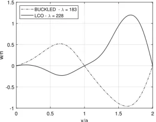
Fig. 13. Motion shapes for 𝛥𝑇 ∕𝛥𝑇𝑏𝑢𝑐𝑘= 2revealing buckled panel prior to multi-bay
panel oscillations.
aeroelastic evolution for thermal loading for 𝛥𝑇 ∕𝛥𝑇𝑏𝑢𝑐𝑘= 0, 1, and 2. It worth noticing that for 𝛥𝑇 ∕𝛥𝑇𝑏𝑢𝑐𝑘= 2the first mode is non-oscillatory for lower 𝜆 values (that is, 𝜆 < 180), which reveals the panel buckling. Moreover, with the increase of 𝜆, a small stable region appears between the buckled condition and the unstable aeroelastic solution.
The differences between the single and multi-bay Hopf bifurcation behavior when the ratio 𝛥𝑇 ∕𝛥𝑇𝑏𝑢𝑐𝑘= 2were also investigated through the time responses features.Fig. 15depicts the time histories and the respective phase portrait of both panel configurations for 𝛥𝑇 ∕𝛥𝑇𝑏𝑢𝑐𝑘= 2. The comparison between both results ensures the existence of a difference at 𝜆 = 190, when for the single panel the unbuckled and dynamically stable solutions are observed, in contradiction with the multi-bay panel that has a buckled configuration. Moreover, the time histories show the limit cycle oscillation amplitudes of the point 𝑃2are
higher than at 𝑃1, as well as a more complex orbits structure in the
phase plane.
A final check of the present Rayleigh–Ritz-based model considers its simulation capabilities. Time integration of the nonlinear aeroe-lastic equations of motion for a square panel with 𝜇∕𝑀 = 0.1 and
𝛥𝑇∕𝛥𝑇𝑏𝑢𝑐𝑘 = 1.0 was performed. The transverse displacement and
velocity were taken at point (𝑥, 𝑦) = (3𝑎∕4, 𝑏∕2) (cf. Fig. 1) to yield a phase portrait as depicted inFig. 6.Fig. 6also includes the result obtained for the same case by Zhou et al. [23] but for a larger of dynamic pressure value. The present model simulation for 𝜆 = 800 provides an adequate match with Zhou et al. [23], thereby ensuring appropriate time domain analyses features.
4. Results and discussion
The Rayleigh–Ritz-based model is used to assess the influence of thermal loads on the nonlinear aeroelastic behavior of multi-bay panel flutter. As a reference case, the single squared panel problem param-eters are taken into account. The multi-bay case admits two simply supported adjacent square panels, each one with identical parameters as that of the verification tests of the previous Section. Particular points, one in each panel, is used to retrieve the displacement information, as illustrated inFig. 7.
The results presented in this Section are based on the aeroelastic responses at points 𝑃1and 𝑃2due to initial conditions and time
march-ing steps equal to that in the previous Section. Temperature variations through the ratio 𝛥𝑇 ∕𝛥𝑇𝑏𝑢𝑐𝑘 = 0, 1, and 2 are considered for the
simulations.
The flutter onset and the post-flutter limit cycle oscillation ampli-tude growth at points 𝑃1and 𝑃2are depicted inFig. 8. These oscillatory
motions are characteristics of the Hopf bifurcation behavior. Three different temperature ratios were considered, and the respective square single panel case is also presented. Here, the results reveal the reduction of the flutter dynamic pressure as the temperature rises, which is related to the reduction of the panel stiffness due to the thermal effect. Indeed, the flutter onset for the multi-bay cases coincides with the single panel problem as inFig. 4. Post-flutter oscillations clearly show the bay further downstream (point 𝑃2) presenting the largest transverse
displacements. The bay upstream (point 𝑃1) for the different thermal loading tend to follow the single-bay amplitude values. These features can be confirmed from the time histories and phase portrait of the points 𝑃1 and 𝑃2 as depicted in Figs. 10 and 11, respectively for the three 𝛥𝑇 ∕𝛥𝑇𝑏𝑢𝑐𝑘 values and some post-flutter dynamic pressures. Besides, the response of a multi-bay configuration, the time histories of a single-bay are also shown. It can be noticed that the amplitude for a single-bay is always within the interval of amplitudes defined from the amplitudes of multi-bay configuration. Moreover, as the dynamic pressure increases the limit cycle oscillation frequency also increases.
For the case where 𝛥𝑇 ∕𝛥𝑇𝑏𝑢𝑐𝑘 = 0(no thermal loading), one can
observe that the limit cycle amplitudes at 𝑃1and 𝑃2have two distinct paths. After the flutter dynamic pressure (𝜆 ≈ 524), displacement at
𝑃1 increases in a smaller rate when compared to the displacement at
𝑃2. Suddenly, at 𝜆 > 624 the amplitudes of 𝑃1 and 𝑃2 increase. This
jump in amplitudes has been detected by Pacheco et al. [7] that show the reason for this effect is a sudden change in motion phase allowed by the freedom in the rotation of the simply supported boundary condition between adjacent bays. The observation of Fig. 8 for the case when 𝛥𝑇 ∕𝛥𝑇𝑏𝑢𝑐𝑘 = 1 indicates the same post-flutter oscillatory
Fig. 14. Stability boundaries for the single and multi-bay panels.
Fig. 15. Time histories and phase portrait for 𝛥𝑇 ∕𝛥𝑇𝑏𝑢𝑐𝑘= 2and 𝜆 = 190 revealing buckled panel to multi-bay panel and a stable panel for single panel configuration.
𝜆 ≈ 344and the amplitudes of the point 𝑃2 are slightly smaller than
in the case for 𝛥𝑇 ∕𝛥𝑇𝑏𝑢𝑐𝑘 = 0. A closer inspection of Fig. 8reveals
that the oscillation amplitude 𝑤∕ℎ jumps from almost 0.8 to 1.5 for
𝛥𝑇∕𝛥𝑇𝑏𝑢𝑐𝑘 = 1. Survey amplitude jump events for nonlinear multi-bay panel cases are important for guaranteeing the correct structural design regarding operations in supersonic flow regime. Because the thermal effect leads to stiffness reduction, these limit cycle oscillations amplitudes are smaller. The jump phenomenon is also present at 𝜆 ≈ 420, being the upstream bay with similar amplitudes of the case with no thermal loading.
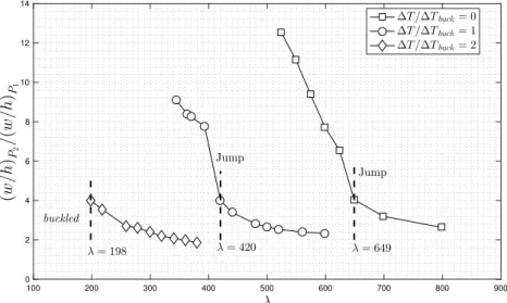
The post-flutter behavior for the cases inFig. 8also show different pattern of evolution between the amplitudes of points 𝑃1 and 𝑃2. Fig. 9shows the ratios between the amplitudes 𝑤∕ℎ at points 𝑃1and
𝑃2 ((𝑤∕ℎ)𝑃
2∕(𝑤∕ℎ)𝑃1) with respect to the dynamic pressure evolution.
Except for 𝛥𝑇 ∕𝛥𝑇𝑏𝑢𝑐𝑘 = 2, the pre- and post-jump conditions present
different changes in the amplitudes ratio, which can be associated with different flutter mechanism.
Figs. 10and11can be used to observe the 𝑤∕ℎ motions at different dynamic pressures and thermal loading. It is clear the influence of temperature in the panel dynamics for the single and multi-bay cases.
Moreover, the time histories and phase portraits corroborate to show that the single bay panel post-flutter responses may be misleading, rather than considering multiple adjacent bays. Fig. 12presents the pre- and post-jump multi-bay panel motion shapes of the panel center line coinciding with the flow direction. For the cases of no thermal loading (cf.Fig. 12(a)) and 𝛥𝑇 ∕𝛥𝑇𝑏𝑢𝑐𝑘= 1(cf.Fig. 12(b)), it is observed
that the jump phenomenon is triggered by a change in motion phase between the upstream and downstream bays, respectively, through the rotational degree of freedom at the boundary between those bays.
Figs. 8–11 at 𝛥𝑇 ∕𝛥𝑇𝑏𝑢𝑐𝑘 = 2 reveals an interesting difference
between the single panel solution and the multi-bay panel solution regarding the Hopf bifurcation. It means that, although a single panel solution presents a small 𝜆 gap of stability between a buckled and a dynamically unstable configuration, the same characteristic vanishes in the multi-bay solution. Therefore, only buckled or limit cycle solutions are present. For the case where 𝛥𝑇 ∕𝛥𝑇𝑏𝑢𝑐𝑘 = 2, the multi-bay flutter
onset (𝜆 ≈ 198) occurs from the buckled panel solution. Moreover, it is observed that the amplitude ratio (𝑤∕ℎ)𝑃
2∕(𝑤∕ℎ)𝑃1 versus 𝜆, giving in
Fig. 9, for 𝛥𝑇 ∕𝛥𝑇𝑏𝑢𝑐𝑘= 2follows the same pattern as that of the
Fig. 16. Power spectra of the aeroelastic signal at different 𝛥𝑇 ∕𝛥𝑇𝑏𝑢𝑐𝑘and 𝜆 values for the single and multi-bay panels.
shape of the panel together with the limit cycle oscillation shape at the panel center-line (in the flow direction). There is not an intermediate motion solution before flutter, which occurs with the bays oscillating out of phase as already observed for the pre-jump conditions for the cases inFig. 12. The limit cycles amplitudes present much larger initial values in post-flutter range when compared to a smoother transition for lower thermal loading.
The dynamic pressure and thermal loading parameter 𝛥𝑇 ∕𝛥𝑇𝑏𝑢𝑐𝑘 range unveils the regions for general behavior of panel in the supersonic regime. Fig. 14provides an overview of the main dynamics for the
case of single and multi-bay panels, respectively. For both cases, the stability boundaries have very similar regions regarding dynamically stable (damped solutions), buckled panel (static instability), limit cycle oscillations, and periodic and chaotic vibrations. For the single panel case (cf.Fig. 14(a)) it can be observed the typical range where thermal loading induces buckling at lower dynamic pressure excitation. At a certain level of 𝜆, flutter manifests leading to a region of limit cycle oscillations. Temperature increments clearly show that flutter onset is also occurring for lower dynamic pressures.Fig. 14(b)reveals that for the multi-bay panel case, the buckled behavior region is similar
to the single panel case. The results show a little anticipation of the transition from buckled to limit cycle oscillations near 𝛥𝑇 ∕𝛥𝑇𝑏𝑢𝑐𝑘= 2.
A closer look to the motion shapes for multi-bay panel cases (cf.Fig. 13) allow inferring that the buckled shape works to trigger the out of phase post-jump limit cycle oscillations behavior, characteristic of the lower temperature cases.
Fig. 16depicts the comparison of the dynamic responses spectra (cf. Fig. 10) regarding dynamic pressures for single and multi-bay panels in post-flutter oscillations. Clearly, the signatures of the nonlinearity are evidenced for the cases presented through the existence of a funda-mental frequency and its odd harmonics. The multi-bay configuration has the fundamental frequencies of each bay slight deviated (smaller) than that of the single panel. Moreover, the multi-bay panel presents higher energy for higher dynamic pressures regarding the single panel. An interesting aspect concerns the multi-bay panel for 𝛥𝑇 ∕𝛥𝑇𝑏𝑢𝑐𝑘 = 2
and small dynamic pressures. A slight augmentation of the dynamic pressure, from 𝜆 = 205 to 𝜆 = 228, leads to abrupt modification of the spectrum. RegardingFig. 16(c), one observes an increment of the signal frequency content, which is not necessarily related to the fundamental frequency. The corresponding phase portrait diagram (cf. Fig. 11) shows the trajectories for the panel positions 𝑃1 and 𝑃2 performing
non-harmonic motion. This characteristic highlights the ability to attain potentially chaotic responses. Indeed, the Hopf bifurcation might lead to double-period responses (cf. Figs. 15(b) and16(c)) that evolve to chaos [28].
5. Concluding remarks
The numerical aeroelastic analysis of multi-bay isotropic panels admitting thermal effects in the supersonic regime was presented in this paper. The multi-bay panel aeroelastic model was based on the principles of classical plate theory, geometric structural nonlinearity adopting the von Kármán strain–displacement relations, the first or-der piston theory unsteady aerodynamics, and a semi-analytical Ritz type model combined with a modified Newmark method for efficient time integration computation. Particular attention was devoted to the aeroelastic response with thermal loading on the post-flutter behavior between single and multi-bay panels, an issue that has not been covered in the literature to the best of the authors’ knowledge. The aim is to access the temperature influence of multi-bay panels and detect differences concerning single panel cases, thereby inferring about the importance of using multi-bay panels in supersonic flutter analyses.
The numerical evaluations, as expected, highlighted the tempera-ture detrimental aspect in the nonlinear aeroelastic behavior. Notwith-standing, the comparison between single and multi-bay panels did show significant differences regarding the nonlinear response of multi-bay panels. As stated in the literature, the existence of jumps in the limit cycle amplitudes when increasing the dynamic pressure was also cap-tured for a range of low thermal loading. With higher temperatures, it was observed a straight transition from buckled configuration to flutter oscillations with the same post-jump out of phase motion between the adjacent bays. Moreover, the spectra results exhibit significant qualitative differences in the harmonics weight at odd multiples of the aeroelastic frequency.
Accordingly, the defined approach to evaluate the nonlinear be-havior of fluttering panels with thermal effects seems to be more adequate than the standard procedure that did not take into account the connection between adjacent panels. Despite the single bay analysis generally provides reliable prediction of the flutter onset, it fails to estimate the post-flutter LCO amplitudes of interconnected bays. It corroborates with new findings in the literature that emphasizes the differences in the aeroelastic results of single and assembled panels. Further investigation on multi-bay panels analysis with thermal effects may concentrate on the influence of initial conditions on the post-flutter behavior of multi-bay panels, and a closer look at the buckled to limit cycle jump for higher thermal loading.
CRediT authorship contribution statement
Thiago A.M. Guimarães: Conceptualization, Methodology, Soft-ware, Investigation. Leonardo Sanches: Formal analysis, Methodol-ogy, Validation.Flávio D. Marques: Conceptualization, Formal analy-sis, Investigation.
Declaration of competing interest
The authors declare that they have no known competing finan-cial interests or personal relationships that could have appeared to influence the work reported in this paper.
Acknowledgments
The authors acknowledge the financial support of the Brazilian Agencies: the National Council for Scientific and Technological Devel-opment (CNPq), Brazil (grant #306824/2019-1), the Minas Gerais State Research Agency (FAPEMIG), Brazil, and São Paulo State Research Agency (FAPESP), Brazil (grants #2017/26284-6 and #2017/02926-9). Appendix. Matrices of the equations of motion
𝑴= ℎ𝜌0∫ 𝑎 0 ∫ 𝑏 0 𝑺𝑤𝑺𝑇𝑤𝑑𝑥𝑑𝑦 , 𝑲= ∫ 𝑎 0 ∫ 𝑏 0 [ −𝜕 2𝑺 𝑤 𝜕𝑥2 − 𝜕2𝑺 𝑤 𝜕𝑦2 − 2 𝜕2𝑺 𝑤 𝜕𝑥𝜕𝑦 ] × 𝑫 [ −−𝜕 2𝑺 𝑤 𝜕𝑥2 − 𝜕2𝑺 𝑤 𝜕𝑦2 − 2 𝜕2𝑺 𝑤 𝜕𝑥𝜕𝑦 ]𝑇 𝑑𝑥𝑑𝑦 , 𝑲𝑎=∫ 𝑎 0 ∫ 𝑏 0 𝜕𝑺𝑤 𝜕𝑥 𝑺𝑤𝑑𝑥𝑑𝑦 , 𝑪= ∫ 𝑎 0 ∫ 𝑏 0 𝑺𝑤𝑺𝑇𝑤𝑑𝑥𝑑𝑦 , 𝑲𝐺=∫ 𝑎 0 ∫ 𝑏 0 ( 𝛼𝑥𝑨 [𝜕𝑺 𝑤 𝜕𝑥 ] [𝜕𝑺 𝑤 𝜕𝑥 ]𝑇 +𝛼𝑦𝑨 [𝜕𝑺 𝑤 𝜕𝑦 ] [𝜕𝑺 𝑤 𝜕𝑦 ]𝑇 + 2𝛼𝑥𝑦𝑨 [𝜕𝑺 𝑤 𝜕𝑥 ] [𝜕𝑺 𝑤 𝜕𝑦 ]𝑇) 𝑑𝑥𝑑𝑦 , 𝑲𝑝𝑖=∫ 𝑏 0 ( [ 𝜕𝑺𝑤 𝜕𝑥 |||| 𝑥=𝑎 left 𝟎 ] [𝜕𝑺 𝑤 𝜕𝑥 |||| 𝑥=𝑎 left 𝟎 ]𝑇 − [ 𝟎 𝜕𝑺𝑤 𝜕𝑥 |||| 𝑥=0 right ] [𝜕𝑺 𝑤 𝜕𝑥 |||| 𝑥=𝑎 left 𝟎 ]𝑇 − − [𝜕𝑺 𝑤 𝜕𝑥 |||| 𝑥=𝑎 left 𝟎 ] [ 𝟎 𝜕𝑺𝑤 𝜕𝑥 |||| 𝑥=0 right ]𝑇 + [ 𝟎 𝜕𝑺𝑤 𝜕𝑥 |||| 𝑥=0 right ] [ 𝟎 𝜕𝑺𝑤 𝜕𝑥 |||| 𝑥=0 right ]𝑇) 𝑘𝑟𝑖𝑑𝑦 ,
where the subscripts
l
eft andr
ight denote the left and right hand side panel from the assembly line as proposed inFig. 2.𝑲𝑁 𝐿1= 𝑲2(∶, ∶, 𝑘)𝒒𝒘 𝑇𝑲−1 𝑚𝑲1(∶, ∶, 𝑘)𝒒𝒘𝑇 , 𝑲𝑁 𝐿2= 𝒒𝒘𝑲3(∶, ∶, 𝑘, 𝑙)𝒒𝒘𝑇 , where, 𝑲𝑚=∫ 𝑎 0 ∫ 𝑏 0 [ −𝜕𝑺𝑢 𝜕𝑥 − 𝜕𝑺𝑣 𝜕𝑦 (𝜕𝑺 𝑢 𝜕𝑦 + 𝜕𝑺𝑣 𝜕𝑥 )] × 𝑨 [ −𝜕𝑺𝑢 𝜕𝑥 − 𝜕𝑺𝑣 𝜕𝑦 (𝜕𝑺 𝑢 𝜕𝑦 + 𝜕𝑺𝑣 𝜕𝑥 )]𝑇 𝑑𝑥𝑑𝑦 , 𝑲1(𝑖, 𝑗, 𝑘) = 𝑛𝑢∑+𝑛𝑣 𝑖=1 𝑛𝑢+𝑛𝑣+𝑛𝑤∑ 𝑗=𝑛𝑢+𝑛𝑣+1 𝑛𝑢+𝑛𝑣+𝑛𝑤∑ 𝑘=𝑛𝑢+𝑛𝑣+1∫ 𝑎 0 ∫ 𝑏 0 [ 𝐴11 2 ( 𝜕𝑆𝑢(𝑖) 𝜕𝑥 𝜕𝑆𝑤(𝑘) 𝜕𝑥 𝜕𝑆𝑤(𝑗) 𝜕𝑥 ) +
+ 𝐴21 2 ( 𝜕𝑆𝑣(𝑖) 𝜕𝑦 𝜕𝑆𝑤(𝑘) 𝜕𝑥 𝜕𝑆𝑤(𝑗) 𝜕𝑥 ) +𝐴31 2 ( 𝜕𝑆𝑢(𝑖) 𝜕𝑦 𝜕𝑆𝑤(𝑘) 𝜕𝑥 𝜕𝑆𝑤(𝑗) 𝜕𝑥 + 𝜕𝑆𝑣(𝑖) 𝜕𝑥 𝜕𝑆𝑤(𝑘) 𝜕𝑥 𝜕𝑆𝑤(𝑗) 𝜕𝑥 ) + + 𝐴12 2 ( 𝜕𝑆𝑢(𝑖) 𝜕𝑥 𝜕𝑆𝑤(𝑘) 𝜕𝑦 𝜕𝑆𝑤(𝑗) 𝜕𝑦 ) +𝐴32 2 ( 𝜕𝑆𝑢(𝑖) 𝜕𝑦 𝜕𝑆𝑤(𝑘) 𝜕𝑦 𝜕𝑆𝑤(𝑗) 𝜕𝑦 + 𝜕𝑆𝑣(𝑖) 𝜕𝑥 𝜕𝑆𝑤(𝑘) 𝜕𝑦 𝜕𝑆𝑤(𝑗) 𝜕𝑦 ) + + 𝐴22 2 ( 𝜕𝑆𝑣(𝑖) 𝜕𝑦 𝜕𝑆𝑤(𝑘) 𝜕𝑦 𝜕𝑆𝑤(𝑗) 𝜕𝑦 ) + 𝐴13 ( 𝜕𝑆𝑢(𝑖) 𝜕𝑥 𝜕𝑆𝑤(𝑘) 𝜕𝑥 𝜕𝑆𝑤(𝑗) 𝜕𝑦 ) + 𝐴23 ( 𝜕𝑆𝑣(𝑖) 𝜕𝑦 𝜕𝑆𝑤(𝑘) 𝜕𝑥 𝜕𝑆𝑤(𝑗) 𝜕𝑦 ) + + 𝐴33 ( 𝜕𝑆𝑢(𝑖) 𝜕𝑦 𝜕𝑆𝑤(𝑘) 𝜕𝑥 𝜕𝑆𝑤(𝑗) 𝜕𝑦 + 𝜕𝑆𝑣(𝑖) 𝜕𝑥 𝜕𝑆𝑤(𝑘) 𝜕𝑥 𝜕𝑆𝑤(𝑗) 𝜕𝑦 ) ] 𝑑𝑥𝑑𝑦 , 𝑲2(𝑖, 𝑗, 𝑘) = 𝑛𝑢+𝑛𝑣+𝑛𝑤∑ 𝑖=𝑛𝑢+𝑛𝑣+1 𝑛𝑢∑+𝑛𝑣 𝑗=1 𝑛𝑢+𝑛𝑣+𝑛𝑤∑ 𝑘=𝑛𝑢+𝑛𝑣+1∫ 𝑎 0 ∫ 𝑏 0 [ 𝐴11 ( 𝜕𝑆𝑤(𝑖) 𝜕𝑥 𝜕𝑆𝑤(𝑘) 𝜕𝑥 𝜕𝑆𝑢(𝑗) 𝜕𝑥 ) + + 𝐴21 ( 𝜕𝑆𝑤(𝑖) 𝜕𝑦 𝜕𝑆𝑤(𝑘) 𝜕𝑦 𝜕𝑆𝑢(𝑗) 𝜕𝑥 ) + 𝐴31 ( 𝜕𝑆𝑤(𝑖) 𝜕𝑥 𝜕𝑆𝑤(𝑘) 𝜕𝑦 𝜕𝑆𝑢(𝑗) 𝜕𝑥 + 𝜕𝑆𝑤(𝑖) 𝜕𝑦 𝜕𝑆𝑤(𝑘) 𝜕𝑥 𝜕𝑆𝑢(𝑗) 𝜕𝑥 ) + + 𝐴12 ( 𝜕𝑆𝑤(𝑖) 𝜕𝑥 𝜕𝑆𝑤(𝑘) 𝜕𝑥 𝜕𝑆𝑣(𝑗) 𝜕𝑦 ) + 𝐴32 ( 𝜕𝑆𝑤(𝑖) 𝜕𝑥 𝜕𝑆𝑤(𝑘) 𝜕𝑦 𝜕𝑆𝑣(𝑗) 𝜕𝑦 + 𝜕𝑆𝑤(𝑖) 𝜕𝑦 𝜕𝑆𝑤(𝑘) 𝜕𝑥 𝜕𝑆𝑣(𝑗) 𝜕𝑦 ) + + 𝐴22 ( 𝜕𝑆𝑤(𝑖) 𝜕𝑦 𝜕𝑆𝑤(𝑘) 𝜕𝑦 𝜕𝑆𝑣(𝑗) 𝜕𝑦 ) + 𝐴13 ( 𝜕𝑆𝑤(𝑖) 𝜕𝑥 𝜕𝑆𝑤(𝑘) 𝜕𝑥 𝜕𝑆𝑢(𝑗) 𝜕𝑦 + 𝜕𝑆𝑤(𝑖) 𝜕𝑥 𝜕𝑆𝑤(𝑘) 𝜕𝑥 𝜕𝑆𝑣(𝑗) 𝜕𝑥 ) + + 𝐴23 ( 𝜕𝑆𝑤(𝑖) 𝜕𝑦 𝜕𝑆𝑤(𝑘) 𝜕𝑦 𝜕𝑆𝑢(𝑗) 𝜕𝑦 + 𝜕𝑆𝑤(𝑖) 𝜕𝑦 𝜕𝑆𝑤(𝑘) 𝜕𝑦 𝜕𝑆𝑣(𝑗) 𝜕𝑥 ) + + 𝐴33 ( 𝜕𝑆𝑤(𝑖) 𝜕𝑥 𝜕𝑆𝑤(𝑘) 𝜕𝑦 𝜕𝑆𝑢(𝑗) 𝜕𝑦 + 𝜕𝑆𝑤(𝑖) 𝜕𝑥 𝜕𝑆𝑤(𝑘) 𝜕𝑦 𝜕𝑆𝑣(𝑗) 𝜕𝑥 + +𝜕𝑆𝑤(𝑖) 𝜕𝑦 𝜕𝑆𝑤(𝑘) 𝜕𝑥 𝜕𝑆𝑢(𝑗) 𝜕𝑦 + 𝜕𝑆𝑤(𝑖) 𝜕𝑦 𝜕𝑆𝑤(𝑘) 𝜕𝑥 𝜕𝑆𝑣(𝑗) 𝜕𝑥 )] 𝑑𝑥𝑑𝑦 , 𝑲3(𝑖, 𝑗, 𝑘, 𝑙) = 𝑛𝑢+𝑛𝑣+𝑛𝑤∑ 𝑖=𝑛𝑢+𝑛𝑣+1 𝑛𝑢+𝑛𝑣+𝑛𝑤∑ 𝑗=𝑛𝑢+𝑛𝑣+1 𝑛𝑢+𝑛𝑣+𝑛𝑤∑ 𝑘=𝑛𝑢+𝑛𝑣+1 𝑛𝑢+𝑛𝑣+𝑛𝑤∑ 𝑙=𝑛𝑢+𝑛𝑣+1∫ 𝑎 0 ∫ 𝑏 0 [ 𝐴11 2 × ( 𝜕𝑆𝑤(𝑖) 𝜕𝑥 𝜕𝑆𝑤(𝑘) 𝜕𝑥 𝜕𝑆𝑤(𝑙) 𝜕𝑥 𝜕𝑆𝑤(𝑗) 𝜕𝑥 ) + + 𝐴21 2 ( 𝜕𝑆𝑤(𝑖) 𝜕𝑦 𝜕𝑆𝑤(𝑘) 𝜕𝑥 𝜕𝑆𝑤(𝑙) 𝜕𝑥 𝜕𝑆𝑤(𝑗) 𝜕𝑦 ) + + 𝐴31 2 ( 𝜕𝑆𝑤(𝑖) 𝜕𝑥 𝜕𝑆𝑤(𝑘) 𝜕𝑥 𝜕𝑆𝑤(𝑙) 𝜕𝑥 𝜕𝑆𝑤(𝑗) 𝜕𝑦 + 𝜕𝑆𝑤(𝑖) 𝜕𝑦 𝜕𝑆𝑤(𝑘) 𝜕𝑥 𝜕𝑆𝑤(𝑙) 𝜕𝑥 𝜕𝑆𝑤(𝑗) 𝜕𝑥 ) + + 𝐴12 2 ( 𝜕𝑆𝑤(𝑖) 𝜕𝑥 𝜕𝑆𝑤(𝑘) 𝜕𝑦 𝜕𝑆𝑤(𝑙) 𝜕𝑦 𝜕𝑆𝑤(𝑗) 𝜕𝑥 ) +𝐴22 2 ( 𝜕𝑆𝑤(𝑖) 𝜕𝑦 𝜕𝑆𝑤(𝑘) 𝜕𝑦 𝜕𝑆𝑤(𝑙) 𝜕𝑦 𝜕𝑆𝑤(𝑗) 𝜕𝑦 ) + + 𝐴32 2 ( 𝜕𝑆𝑤(𝑖) 𝜕𝑥 𝜕𝑆𝑤(𝑘) 𝜕𝑦 𝜕𝑆𝑤(𝑙) 𝜕𝑦 𝜕𝑆𝑤(𝑗) 𝜕𝑦 + 𝜕𝑆𝑤(𝑖) 𝜕𝑦 𝜕𝑆𝑤(𝑘) 𝜕𝑦 𝜕𝑆𝑤(𝑙) 𝜕𝑦 𝜕𝑆𝑤(𝑗) 𝜕𝑥 ) + + 𝐴13 2 ( 𝜕𝑆𝑤(𝑖) 𝜕𝑦 𝜕𝑆𝑤(𝑘) 𝜕𝑥 𝜕𝑆𝑤(𝑙) 𝜕𝑥 𝜕𝑆𝑤(𝑗) 𝜕𝑥 ) + + 𝐴23 2 ( 𝜕𝑆𝑤(𝑖) 𝜕𝑦 𝜕𝑆𝑤(𝑘) 𝜕𝑦 𝜕𝑆𝑤(𝑙) 𝜕𝑥 𝜕𝑆𝑤(𝑗) 𝜕𝑦 ) + + 𝐴33 ( 𝜕𝑆𝑤(𝑖) 𝜕𝑥 𝜕𝑆𝑤(𝑘) 𝜕𝑦 𝜕𝑆𝑤(𝑙) 𝜕𝑦 𝜕𝑆𝑤(𝑗) 𝜕𝑥 + 𝜕𝑆𝑤(𝑖) 𝜕𝑦 𝜕𝑆𝑤(𝑘) 𝜕𝑥 𝜕𝑆𝑤(𝑙) 𝜕𝑥 𝜕𝑆𝑤(𝑗) 𝜕𝑦 )] 𝑑𝑥𝑑𝑦 ,
where 𝑛𝑢, 𝑛𝑣, and 𝑛𝑤 represents the lengths of vectors 𝑞𝑢, 𝑞𝑣, and 𝑞𝑤 respectively, and 𝐴𝑖𝑗are the elements of matrix 𝑨 (cf. Eq.(7)).
References
[1] E.H. Dowell, Aeroelasticity of Plates and Shells, Noordhoff International Publishing, 1975.
[2] M. Amabili, F. Pellicano, Nonlinear supersonic flutter of circular cylindrical shells, AIAA J. 39 (4) (2001) 564–573,http://dx.doi.org/10.2514/2.1365. [3] M. Amabili, Nonlinear Vibrations and Stability of Shells and Plates, first ed.,
Cambridge University Press, New York, USA, 2008.
[4] E.H. Dowell, Panel flutter – A review of the aeroelastic stability of plates and shells, AIAA J. 8 (3) (1970) 385–399,http://dx.doi.org/10.2514/3.5680. [5] C. Mei, K. Abdel-Motagaly, R. Chen, Review of nonlinear panel flutter at
supersonic and hypersonic speeds, Appl. Mech. Rev. 52 (1999) 321–332,http: //dx.doi.org/10.1115/1.3098919.
[6] D.R.Q. Pacheco, F.D. Marques, A.J.M. Ferreira, Nonlinear finite element aeroe-lastic analysis of multibay panels in supersonic flow regime, Thin-Walled Struct. 120 (2017) 470–478,http://dx.doi.org/10.1016/j.tws.2017.08.034.
[7] D.R.Q. Pacheco, A.J.M. Ferreira, F.D. Marques, On the effects of structural coupling on the supersonic flutter and limit cycle oscillations of transversely reinforced panels, J. Fluids Struct. 79 (2018) 158–170, http://dx.doi.org/10. 1016/j.jfluidstructs.2018.01.013.
[8] D.R.Q. Pacheco, F.D. Marques, A.J.M. Ferreira, Finite element analysis of fluttering plates reinforced by flexible beams: An energy-based approach, J. Sound Vib. 435 (2018) 135–148,http://dx.doi.org/10.1016/j.jsv.2018.07.042. [9] E.H. Dowell, Flutter of multibay panels at high supersonic speeds, AIAA J. 2
(10) (1964) 1805–1814,http://dx.doi.org/10.2514/3.2669.
[10] E.H. Dowell, On the flutter of multibay panels at low supersonic speeds, AIAA J. 5 (5) (1967) 1032–1033,http://dx.doi.org/10.2514/3.4125.
[11] W.P. Rodden, Flutter of multibay panels at supersonic speeds, AIAA J. 2 (8) (1964) 1476–1478,http://dx.doi.org/10.2514/3.2614.
[12] M.H. Lock, E.F. Farkas, Flutter of two-bay flat panels of infinite span at supersonic Mach numbers, AIAA J. 3 (9) (1965) 1692–1697,http://dx.doi.org/ 10.2514/3.3228.
[13] T.A.M. Guimarães, F.D. Marques, A.J.M. Ferreira, On the modeling of nonlinear supersonic flutter of multibay composite panels, Compos. Struct. 232 (2020)
http://dx.doi.org/10.1016/j.compstruct.2019.111522.
[14] J.N. Reddy, Mechanics of Laminated Composite Plates and Shells: Theory and Analysis, second ed., CRC Press, 2004.
[15] R.R. Craig, A.J. Kurdila, Fundamentals of Structural Dynamics, Wiley, 2006.
[16] H. Ashley, G. Zartarian, Piston theory – A new aerodynamic tool for the aeroelastician, J. Aeronaut. Sci. 23 (12) (1956) 1109–1118,http://dx.doi.org/ 10.2514/8.3740.
[17] S.C. Nixon, Comparison of Panel Flutter Results from Approximate Aerodynamic Theory with Results from Exact Inviscid Theory and Experiment, Technical Report, NASA Langley Research Center – NASA TN D-3649, 1966.
[18] M. Amabili, F. Pellicano, Multimode approach to nonlinear supersonic flutter of imperfect circular cylindrical shells, J. Appl. Mech. 69 (2) (2001) 117–129,
http://dx.doi.org/10.1115/1.1435366.
[19] M. Amabili, I.D. Breslavsky, Displacement dependent pressure load for finite deflection of doubly-curved thick shells and plates, Int. J. Non-Linear Mech. 77 (2015) 265–273,http://dx.doi.org/10.1016/j.ijnonlinmec.2015.09.007. [20] M. Amabili, Nonlinear Mechanics of Shells and Plates: Composite, Soft and
Biological Materials, Cambridge University Press, New York, USA, 2018.
[21] S.G.P. Castro, T.A.M. Guimarães, D.A. Rade, M.V. Donadon, Flutter of stiffened composite panels considering the stiffener’s base as a structural element, Compos. Struct. 140 (2016) 36–43,http://dx.doi.org/10.1016/j.compstruct.2015.12.056. [22] S.G.P. Castro, M.V. Donadon, Assembly of semi-analytical models to address lin-ear buckling and vibration of stiffened composite panels with debonding defect, Compos. Struct. 160 (2017) 232–247,http://dx.doi.org/10.1016/j.compstruct. 2016.10.026.
[23] R.C. Zhou, D.Y. Xue, C. Mei, Finite element time domain - Modal formulation for nonlinear flutter of composite panels, AIAA J. 32 (10) (1994) 2044–2052,
http://dx.doi.org/10.2514/3.12250.
[24] V.V. Vedeneev, Panel flutter at low supersonic speeds, J. Fluids Struct. 29 (2012) 79–96,http://dx.doi.org/10.1016/j.jfluidstructs.2011.12.011.
[25] S. Shitov, V.V. Vedeneev, Flutter of rectangular simply supported plates at low supersonic speeds, J. Fluids Struct. 69 (2017) 154–173,http://dx.doi.org/10. 1016/j.jfluidstructs.2016.11.014.
[26] J.K. Chen, C.T. Sun, Nonlinear transient responses of initially stressed composite plates, Comput. Struct. 21 (3) (1985) 513–520, http://dx.doi.org/10.1016/0045-7949(85)90130-0.
[27] E.H. Dowell, Nonlinear oscillations of a fluttering plate, AIAA J. 4 (7) (1966) 1267–1275,http://dx.doi.org/10.2514/3.3658.
[28] A.H. Nayfeh, B. Balachandran, Applied Nonlinear Dynamics: Analytical, Com-putational, and Experimental Methods, John Wiley & Sons, New York, 1995.
[29] A. Shishaeva, V. Vedeneev, A. Aksenov, G. Sushko, Transonic panel flutter in accelerating or decelerating flow conditions, AIAA J. 56 (3) (2018) 997–1010,