Science Arts & Métiers (SAM)
is an open access repository that collects the work of Arts et Métiers Institute of
Technology researchers and makes it freely available over the web where possible.
This is an author-deposited version published in:
https://sam.ensam.eu
Handle ID: .
http://hdl.handle.net/10985/11348
To cite this version :
Gérard POULACHON, José OUTEIRO, Christophe RAMIREZ, Victorien ANDRÉ, Guillaume
ABRIVARD - Hole surface topography and tool wear in CFRP drilling - In: 3rd CIRP Conference
on Surface Integrity (CIRP CSI), Etats-Unis, 2016-06-04 - Procedia CIRP - 2016
Any correspondence concerning this service should be sent to the repository
Procedia CIRP 45 ( 2016 ) 35 – 38
2212-8271 © 2016 The Authors. Published by Elsevier B.V. This is an open access article under the CC BY-NC-ND license (http://creativecommons.org/licenses/by-nc-nd/4.0/).
Peer-review under responsibility of the scientific committee of the 3rd CIRP Conference on Surface Integrity (CIRP CSI) doi: 10.1016/j.procir.2016.02.348
ScienceDirect
3
rdCIRP Conference on Surface Integrity (CIRP CSI)
Hole surface topography and tool wear in CFRP drilling
Gérard Poulachon
a*, José Outeiro
a, Christophe Ramirez
a,Victorien André
a, Guillaume Abrivard
b aArts et Metiers ParisTech, rue porte de Paris, Cluny 71250, France
b
Airbus Group Innovations, Technocampus Center EMC2, chemin du Chaffault, Bouguenais 44340, France
* Corresponding author. Tel.: +33-385-595-342; fax: +33-385-595-370. E-mail address: [email protected]
Abstract
This paper deals with the hole surface quality when CFRP drilling. Mechanical instrumented operations have enabled to follow precisely the damage on the tool margins and the main cutting edges. The amount of uncut fibers according to the drill wear was evaluated with a roundness/cylindricity device versus the fiber’s orientation and the tool damage. Thus, according to the hole’s diameter tolerance, a wear criterion was defined to limit the number of holes achievable. This method has been carried out on unidirectional (UD) CFRP and then transposed on multidirectional (MD) CFRP. A model developed under Matlab was applied to predict the global topography of the hole surface.
© 2016 The Authors. Published by Elsevier B.V.
Peer-review under responsibility of the scientific committee of the 3rd CIRP Conference on Surface Integrity (CIRP CSI)
Keywords: Drilling, composite, surface integrity, tool wear.
1.Introduction
The increase in the manufacturing of new airplanes reaches 5% per year. Due to this new economic and environmental issues, the aeronautic sector is conducting research to improve their products through different technological solutions such as weight reduction, development of new manufacturing processes combined with innovative materials. All these solutions are more suitable for the environment. It is in this context that for several years, aeronautic companies are using huge amount of materials such as composites and titanium alloys. The combination of these two materials named stack, allows building light structures with maintaining good mechanical properties. Using those new methods, companies are able to make more efficient and more economical products. However, this practice has obviously led towards new difficulties in machining and especially in drilling operation.
The present study focuses on CFRP (Carbon Fiber Reinforced Plastic) drilling composite plate only, with the final objective to drill Ti/CFRP stacks. According to Bonnet et al. [1] during titanium alloy drilling, the cutting temperature
may reach high value, whereas the epoxide resin of CFRP is subjected to resist approximately at 180°C, due to the carbonization. Moreover, tool wear will be accelerated due to the severe abrasive nature of the carbon fibers. As a consequence, the fiber delamination at hole surface will be discussed in this present study.
The main aim of this research is to find the consequences of the drill wear on the surface quality of the hole such us the uncut fibers and dimensional variation of the diameter in the case of an unidirectional (UD) CFRP composite. Then, the experimental approach used for UD will be extended to multi-directional (MD) CFRP composite.
2.State of the art
In order to study the influence of fiber orientation on the mechanical loading, it is necessary to use specific angles to describe the position of the tool cutting edge in relation to the carbon fiber orientation. Kivimaa [2] and McKenzie [3] have defined a notation for wood cutting that can be easily applied in the case of CFRP drilling by defining two orientation fiber angles regarding to the cutting edge and the cutting direction.
© 2016 The Authors. Published by Elsevier B.V. This is an open access article under the CC BY-NC-ND license (http://creativecommons.org/licenses/by-nc-nd/4.0/).
36 Gérard Poulachon et al. / Procedia CIRP 45 ( 2016 ) 35 – 38
Fig.1 describes those angles denoted by χ1 and χ2 which are
respectively formed between the direction of the cutting edge or the cutting speed direction with the fiber axis.
For CFRP the cutting mechanisms depend on the orientation of the fibers [4] relative to the cutting direction (χ2). Fig. 2 clearly shows the influence of the fiber orientation
in particular for the value -45° which is not suitable for the surface quality and moreover will induce a rapid flank wear due to the elastic spring back of the fiber. The rake angle has also a significant influence on those mechanisms. Wang [5] summarized all of these possibilities as shown in Fig. 2.
Fig. 1. Elementary configuration of cutting fibers (cutting modes) [3].
Fig. 2. Chip formation mechanisms in CFRP machining.
Many studies focus on peel-up or push-down delamination of the hole, but there are too few researches related to the surface integrity within the hole surface. The main defect which may appear is a high surface roughness due to uncut fibers cause to the cutting mechanisms mentioned by Wang [4]. For drilling unidirectional CFRP, χ2 evolves from 0° to
360°, and according to Ramirez [6] the maximal surface roughness default takes place for χ2 equal to 135° or 135°+kS
(315°).
Drilling is one of the most important operations in the manufacturing of aeronautic structures because of the large number of drilled holes. However, tool wear is an obstacle when drilling composite. Actually, due to its abrasive character, CFRP composite is causing fast tool wear leading to rapid surface damage.
Bonnet [1] has shown that 55% of the cutting torque is due to the main cutting edge and the remain portion (45%) is the contribution of the margins. Moreover, the cutting edges are responsible of 100% the feed force as highlighted in Fig.3.
Faraz [7] have introduced the measurement of the cutting
edge roundness (CER) as a wear criterion in CFRP drilling.
Fig. 3. Contribution of the tool cutting edges and margins on the drilling torque and feed force [1].
He showed in the case of uncoated carbide tools that the relationship between the CER and forces present a linear evolution. Rawat [8] highlighted that there is also chipping during CFRP drilling in combination with abrasive wear. He noticed that flaking occurs during the first holes and are partly due to carbon fibers. When the drill edges present a fine sharpness, this one is not enough resistant to undergo the high stresses imposed by the carbon fibers, leading to pulled out some carbide grains of the cobalt binder which induces chipping.
Park [9] has measured the wear on WC and PCD tools during CFRP/titanium stacks drilling. He noticed that the carbon fibers may weaken the cobalt binder and therefore accelerate the risk of drill chipping and fracture.
3.Experimental setup
The drilling tests were performed on a 5 axis Mikron HSM600 CNC milling center. After each drilled hole, tool geometry variation induced by wear was measured between 1.6 mm and 2.5 mm from the drill chisel edge in y-direction (DL distance in Fig. 4), using a Blum laser (4 µ m resolution) installed in the machine-tool. Since the margins wear affects the hole diameter, the evolution of this one in function of the number of drilled holes was monitored.
Two uncoated carbide drills from SECO Tools, reference SD205A 12.0-56-12R1-T, having 140° tool tip angle, 12 mm of diameter, 1% back taper and a variable rake angle along the cutting edge (equal to 30° at the tool corner) were used. The hole dimensional tolerance used in this manufactured stacks is ø12G9 (+0.006/+0.049).
UD and MD CFRP composite plates of T800M21 with 60% of fiber contents and an epoxide resin have been drilled. The fiber diameter is approximately 5 µm and the ply thickness about 250 µm. MD CFRP composite plates presents an irregular arrangement (20%/-45°; 11%/0°; 18%/45°; 50%/90°). The thickness of all the plates was 35 mm.
The drilling tests were conducted under dry cutting conditions with a cutting speed (vc) equal to 100 m/min and a feed (f) of 0,05 mm/rev, close to the industrial cutting conditions.
The uncut fibers in terms of angular positions and lengths, as well as the hole diameter were measured using a Taylor Hobson 585 roundness/cylindricity instrument.
Fig. 4. Tool wear measurements with Blum laser.
4.Results and discussion
4.1.Drill corner/margins wear
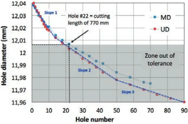
Drill corner/margins wear have a strong influence in the hole surface integrity and tolerances (hole diameter). Therefore, drill corner geometry was measured with the Blum laser after each hole being drilled as indicated on Fig. 5. A total of 70 measurements (corresponding to 70 holes) were performed. From hole #3 an inversion in the drill back taper angle is visible. After hole # 22 (770 mm drilled depth), the hole diameter becomes out of tolerance (inferior to 12,006 mm) as shown in Fig. 6. This figure shows the decrease in hole diameter in function of the number of holes being drilled. These curves could be approximated by three rectilinear lines with various slopes. These various slopes are due to different tool wear regimes, which are related to the ratio between the surface of the uncut fibers and the total hole surface [6]. In our study case, the drill life time is represented by the more accentuated slope. These results point out the severe abrasive wear of the carbon fibers on the drill and their consequences on the hole geometry.
Fig. 5. Evolution of the drill corner geometry in function of the number of holes being drilled.
4.2.Characterization of the surface topography
Fig. 7 shows the hole surface of UD CFRP after samples being cut along the axial direction. The dashed rectangles limit the zones having the uncut fibers. As shown in this figure, there is an increase of the amount of uncut fibers with the number of holes, due to the increase of tool wear, in particular the margins damage (see Fig. 6). Moreover, the amount of uncut fibers is negligible up to hole #3 (cutting length of 90 mm), then it increases up to a maximum value of about 20% of the total hole surface [6].
Fig. 6. Evolution of the hole geometry for both UD and MD CFRP in function of the number of holes.
As shown by Ramirez et al. [6] for the case of UD CFRP, the uncut fibers areas are localized at 135°±18° and 315°±18°, as shown in Fig. 8. The explanation of these both zone positions are relevant with the cutting mechanisms presented in Fig. 2 [6]. Fig. 9 shows the surface roughness profile obtained by the roundness/cylindricity instrument. As shown in this figure, the uncut fibers heights vary between 60 and 100 μm while the variation does not exceed 10 μm on the rest of the profile [6].
Fig. 7. Evolution of the hole surface topography in UD CFRP with the number of hole being drilled, using the same drill (uncut fibers inside the dashed rectangles).
In the case of MD CFRP, the orientation of the fibers changes from one ply to another. Therefore, according to cutting
Uncut fibers
38 Gérard Poulachon et al. / Procedia CIRP 45 ( 2016 ) 35 – 38
mechanisms presented in Fig. 2 the distribution of the uncut fibers in the hole surface should change when compared to the UD CFRP. Fig. 10 shows the measured distribution of uncut fibers around the hole surface. A regular uncut fibers pattern is observed at hole #10 being drilled, whereas an irregular pattern is observed at hole #34 or more. In order to predict these patterns for MD CFRP based on the knowledge of the uncut fibers pattern for UD CFRP, an algorithm was developed under Matlab environment. The same figure shows the predicted uncut fibers pattern at the hole surface. The predicted results point out these two kinds of patterns observed experimentally. This pattern change from hole #10 to #34 is due to tool geometry modifications induced by tool wear. For low tool wear the uncut fibers distribution is due to the fibers orientation. However, when tool wear increases and become significant, the distribution of the uncut fibers is less dependent of the fibers orientation. Therefore, a random uncut fiber distribution is obtained.
This algorithm can be used efficiently to predict the distribution of the uncut fibers for different ply fiber orientations based on the knowledge of the uncut fibers pattern for UD CFRP.
Fig. 8. Localization of the uncut fibers in a drilled UD CFRP hole [5].
Fig. 9. Surface roughness profile for UD CFRP [5]. 5.Conclusions
This work has permitted to find results directly used for industrial purposes as regards to CFRP drilling. The
experiments have shown the severe abrasive wear undergone by the main and secondary (margin) edges. According to the diameter tolerance, only 22 holes (30 mm depth) can be made in respect of the specifications. We remind that the main goal of this work is to drill holes in CFRP/Titanium stack, which is a bigger challenge since the high heat generated by cutting titanium alloy will reduce tool-life and causes the degradation of the CFRP epoxy resin. The inspection of the hole surface has shown clearly that the uncut fiber may reach 100 µm length and are oriented on the whole surface according to the CFRP plies arrangement. In this case of anisotropic and inhomogeneous material, it will be necessary to redefine new surface roughness criterion.
Fig. 10. Measured and predicted distribution of the uncut fibers around the holes for MD CFRP (20 Pm/div), after hole number #10 and #34. Acknowledgements
The cutting tools and CFRP composite used in this work were provided by SECO tools and AIRBUS, respectively. The author gratefully acknowledges their support.
References
[1] Bonnet, C., Poulachon, G., Rech, J., Girard, Y., Costes, J.-P., 2015, CFRP drilling: Fundamental study of local feed force and consequences on hole exit damage International Journal of Machine Tools and Manufacture 94, p. 57-64.
[2] E. Kivimaa, Cutting Force in Wood Working. Helsinki, State Institute for Technical Research, 1950.
[3] W. M. McKenzie. Fundamental aspects of the wood cutting process. Forest Products Journal 10, 1960, p. 447-456.
[4] Henerichs, M.,Voß, R.,Kuster, F.,Wegener, K., 2015. Machining of carbon fiber reinforced plastics: Influence of tool geometry and fiber orientation on the machining forces. CIRP Journal of Manufacturing Science and Technology 9, p.136-145.
[5] Wang, D. H., Ramulu, M., Arola, D, 1995, Orthogonal cutting mechanisms of graphite / epoxy composite. Part I : unidirectional laminate. International Journal of Machine Tools & Manufacture 35/12, p. 1623-1638.
[6] Ramirez, C., Poulachon, G., Rossi, F., M’Saoubi, R., 2014, Tool wear monitoring and hole surface quality during CFRP drilling, 2nd CIRP 2nd CIRP Conference on Surface Integrity (CSI), Procedia CIRP, p. 163-168. [7] Faraz, A., Biermann, D., Weinert, K., 2009, Cutting edge rounding : An
innovative tool wear criterion in drilling CFRP composite laminates. International Journal of Machine Tools & Manufacture 49, p. 1185-1196. [8] Rawat, S., Attia, H., 2009, Wear mechanisms and tool life management of
WC–Co drills during dry high speed drilling of woven carbon fibre composites. Wear 267, p. 1022-1030.
[9] Park, K., Beal, A., Kim, D., Kwon, P., Lantrip, J., 2011, Tool wear in drilling of composite/titanium stacks using carbide and polycrystalline diamond tools. Wear 271, p. 2826-2835.
![Fig. 1. Elementary configuration of cutting fibers (cutting modes) [3].](https://thumb-eu.123doks.com/thumbv2/123doknet/7320457.210725/3.892.495.729.138.388/fig-elementary-configuration-cutting-fibers-cutting-modes.webp)
![Fig. 8. Localization of the uncut fibers in a drilled UD CFRP hole [5].](https://thumb-eu.123doks.com/thumbv2/123doknet/7320457.210725/5.892.465.788.322.474/fig-localization-uncut-fibers-drilled-ud-cfrp-hole.webp)
