SHERBROOKE
Faculte de genie
Departement de genie civil
SHEAR BEHAVIOUR OF CONCRETE BEAMS REINFORCED
WITH FIBRE-REINFORCED POLYMER (FRP) STIRRUPS
ETUDE DU COMPORTEMENT A L'EFFORT TRANCHANT DE
POUTRES EN BETON ARME AVEC DES ETRIERS EN
POLYMERE RENFORCE DE FIBRES (PRF)
These de doctorat es sciences appliquees Specialite : genie civil
Jury: Richard Gagne Pierre Labossiere Brahim Benmokrane Ehab El-Salakawy Mark F. Green David Lai President Rapporteur Directeur de recherche Codirecteur Examinateur Examinateur
Ehab Abdul-Mageed AHMED
1*1
Published Heritage Branch 395 Wellington Street OttawaONK1A0N4 Canada Direction du Patrimoine de I'edition 395, rue Wellington OttawaONK1A0N4 CanadaYour file Votre reference ISBN: 978-0-494-52815-0 Our file Notre reference ISBN: 978-0-494-52815-0
NOTICE: AVIS:
The author has granted a
non-exclusive license allowing Library and Archives Canada to reproduce,
publish, archive, preserve, conserve, communicate to the public by
telecommunication or on the Internet, loan, distribute and sell theses
worldwide, for commercial or non-commercial purposes, in microform, paper, electronic and/or any other formats.
L'auteur a accorde une licence non exclusive permettant a la Bibliotheque et Archives Canada de reproduire, publier, archiver, sauvegarder, conserver, transmettre au public par telecommunication ou par I'lnternet, preter, distribuer et vendre des theses partout dans le monde, a des fins commerciales ou autres, sur support microforme, papier, electronique et/ou autres formats.
The author retains copyright ownership and moral rights in this thesis. Neither the thesis nor substantial extracts from it may be printed or otherwise reproduced without the author's permission.
L'auteur conserve la propriete du droit d'auteur et des droits moraux qui protege cette these. Ni la these ni des extraits substantiels de celle-ci ne doivent etre imprimes ou autrement
reproduits sans son autorisation.
In compliance with the Canadian Privacy Act some supporting forms may have been removed from this thesis.
Conformement a la loi canadienne sur la protection de la vie privee, quelques
formulaires secondaires ont ete enleves de cette these.
While these forms may be included in the document page count, their removal does not represent any loss of content from the thesis.
Bien que ces formulaires aient inclus dans la pagination, il n'y aura aucun contenu manquant.
1*1
Canada
ABSTRACT
Corrosion of steel reinforcement is a major cause of deterioration in reinforced concrete structures especially those exposed to harsh environmental conditions such as bridges, concrete pavements, and parking garages. The climatic conditions may have a hand in accelerating the corrosion process when large amounts of salts are used for ice removal during winter season. These conditions normally accelerate the need of costly repairs and may lead, ultimately, to catastrophic failure. Therefore, using the non-corrodible fibre-reinforced polymer (FRP) materials as an alternative reinforcement in prestressed and reinforced concrete structures is becoming a more accepted practice in structural members subjected to severe environmental exposure. This, in turn, eliminates the potential of corrosion and the associated deterioration.
Stirrups for shear reinforcement normally enclose the longitudinal reinforcement and are thus the closest reinforcement to the outer concrete surface. Consequently, they are more susceptible to severe environmental conditions and may be subjected to related deterioration, which reduces the service life of the structure. Thus, replacing the conventional stirrups with the non-corrodible FRP ones is a promising aspect to provide more protection for structural members subjected to severe environmental exposure. However, from the design point of view, the direct replacement of steel with FRP bars is not possible due to various differences in the mechanical and physical properties of the FRP materials compared to steel. These differences include higher tensile strength, lower modulus of elasticity, different bond characteristics, and absence of a yielding plateau in the stress-strain relationships of FRP materials. Moreover, the use of FRP as shear reinforcement (stirrups) for concrete members has not been sufficiently explored to provide a rational model and satisfactory guidelines to predict the shear strength of concrete members reinforced with such type of stirrups.
An experimental program to investigate the structural performance of FRP stirrups as shear reinforcement for concrete beams was conducted. The experimental program included seven large-scale T-beams reinforced with FRP and steel stirrups. Three beams were reinforced with CFRP stirrups, three beams reinforced with GFRP stirrups, and one beam reinforced with steel stirrups. The geometry of the T-beam was selected to simulate the New England Bulb Tee Beam (NEBT) that is being used by the Ministry of Transportation of
Quebec (MTQ), Canada. The beams were 7.0 m long with a T-shaped cross section measuring a total height of 700 mm, web width of 180 mm, flange width of 750 mm, and flange thickness of 85 mm. The large-scale T-beams were constructed using normal-strength concrete and tested in four-point bending over a clear span of 6.0 m till failure to investigate the modes of failure and the ultimate capacity of the FRP stirrups in beam action. The test variables considered in this investigation were the material of the stirrups, shear reinforcement ratio, and stirrup spacing. The specimens were designed to fail in shear to utilize the full capacity of the FRP stirrups. Six beams failed in shear due to FRP (carbon and glass) stirrup rupture or steel stirrup yielding. The seventh beam, reinforced with CFRP stirrups spaced at
d/4, failed in flexure due to yielding of the longitudinal reinforcement followed by crushing of
concrete. The effects of the different test parameters on the shear behaviour of the concrete beams reinforced with FRP stirrups were presented and discussed. The test results contributed to amending the shear provisions incorporated in the Canadian Highway Bridge Design Code (CAN/CSA-S6) and the updated provisions were approved in the CSA-S6-Addendum (CSA 2009).
An analytical investigation was conducted to evaluate the validity and accuracy of available FRP codes and guidelines in Japan, Europe, and North America. The predictions of the codes and the guidelines were verified against the results of the tested beams as well as 24 other beams reinforced with FRP stirrups from the literature. The tested beams were also analysed using various shear theories including the modified compression field theory (MCFT), the shear friction model (SFM), and the unified shear strength model (USSM). A simple equation for predicting the shear crack width in concrete beams reinforced with FRP stirrups is proposed and verified against the experimentally measured values.
RESUME
Etude du comportement a l'effort tranchant de poutres en beton arme avec
des etriers en polymere renforce de fibres (PRF)
La corrosion des armatures en acier est une des plus importantes causes de deterioration des ouvrages en beton arme exposes a des environnements agressifs, comme les ponts, chaussees et stationnements. Les conditions climatiques peuvent accelerer le processus de degradation par corrosion, surtout lors de l'utilisation du sel de deglacage, et engendrer des reparations couteuses, ou dans 1'extreme, des effondrements de structures. Pour ces raisons, le remplacement des armatures en acier par des armatures en PRF, materiaux non corrodables, se fait de plus en plus, surtout dans les elements structuraux exposes a des environnements agressifs.
Les etriers constituent les armatures les plus proches de la surface exterieure du beton. Par consequent, ils sont plus exposes aux conditions environnementales severes qui peuvent les deteriorer plus rapidement (comparativement a 1'armature longitudinale par exemple) et ainsi reduire de facon prematuree la duree de vie des ouvrages. II devient alors evident que l'utilisation des etriers non corrodables en PRF au lieu de ceux en acier, permet aux structures exposees a des environnements agressifs des longevites plus accrues. Cependant, le dimensionnement a l'effort tranchant avec des etriers en PRF est different de celui de ceux d'acier a cause des differences sur les proprietes mecaniques de ces deux materiaux. En effet, les PRF ont une resistance en traction plus elevee que celle de 1'acier, un module plus faible et un comportement en traction elastique lineaire jusqu'a la rupture. De plus, la litterature rapporte peu de travaux et d'etudes sur l'utilisation des etriers en PRF comme armature de cisaillement.
Afin de combler ce besoin, un programme de recherche, constitue d'etudes experimentales et d'etudes theoriques, a ete entrepris a l'Universite de Sherbrooke, dans le cadre de la Chaire de recherche du CRSNG sur les «Materiaux composites novateurs de PRF pour les infrastructures», pour investiguer les performances des etriers en PRF comme armature de cisaillement (etiers) dans des poutres. Les etudes experimentales comprennent 1'evaluation du comportement a 1'effort tranchant de sept poutres de section en T de grandes dimensions, renforcees en cisaillement par des etriers en PRF et en acier. Parmi ces poutres,
trois ont ete renforcees avec des etriers en PRF de carbone, trois avec des etriers en PRF de verre et une avec des etriers en acier. La geometrie des poutres en T est celle utilisee par le ministere des Transports du Quebec (MTQ). La longueur des poutres est de 7,0 m, avec une section en T de 700 mm de hauteur, une ame de 180 mm de largeur et une dalle (aile) de compression de 750 mm de largeur et 85 mm d'epaisseur. Les sept poutres d'essais ont ete armees en flexion (armature longitudinale de traction) a l'aide de cables de precontrainte torsades tres legerement tendus lors de la mise en place du beton. Aussi, toutes les poutres ont ete construites en utilisant un beton normal et ont ete testees en flexion quatre point sur une portee de 6.0 m jusqu'a la rupture. Les modes de rupture en cisaillement et les capacites des etriers ont ete investigues. Les parametres etudies sont le type d'etriers (PRFC, PRFV et acier), le taux d'armature de cisaillement et l'espacement des etriers. Les poutres d'essais ont ete concues pour rompre en cisaillement afin de sollicker les etriers a leur pleine capacite. Les resultats obtenus ont montre que la rupture de six poutres s'est produite comme prevu par cisaillement ayant conduit a la rupture en traction des etriers pour ceux de PRP (carbone et verre) (carbone et verre) ou en traction par plastification pour ceux en acier. La septieme poutre renforcee avec des etriers en PRFC ayant un espacement de dIA a rompu, quant a elle, en flexion par la plastification des armatures longitudinales d'acier (cables de precontrainte torsadees) et de l'ecrasement du beton. Ces essais ont ainsi permis l'etude et l'analyse de differents parametres sur le comportement en cisaillement de poutres renforcees avec des etriers de PRF.
En parallele aux etudes experimentales, des etudes analytiques ont ete effectuees pour ameliorer et ou optimiser les equations de calcul proposees par les differents codes et guides de calcul traitant de membrures en beton arme de PRF actuellement en usage (CSA, ACI, JSCE). Les predictions des codes et guides ont ete comparees aux resultats des sept poutres testees, ainsi qu'a ceux de 24 autres poutres renforcees avec des etriers en PRF, trouves dans la litterature. Les poutres testees ont aussi ete analysees avec differentes theories de cisaillement, incluant la MCFT ((Modified Compression Field Theory», la SFM «Shear Friction Model» et le ((Unified Shear Strength Model». Une equation simple pour predire la largeur de fissures de cisaillement dans les poutres en beton renforcees par des etriers en PRF a ete proposee et validee avec les resultats experimentaux.
Mots-cles: Materiaux composites, polymeres renforces de fibres, beton, etriers, cisaillement,
effort tranchant, fissures de cisaillement, modeles de prediction, conception, codes de calcul, resistance, poutres de ponts.
AUTHOR'S RESEARCH CONTRIBUTIONS
The candidate has conduced experimental and analytical investigations concerning the shear behaviour of concrete beams reinforced with carbon and glass FRP stirrups. In addition, the candidate has participated in some research activities and publications concerning the bond behaviour of FRP bars, characterization of FRP bent bars/stirrups, GFRP post-installed adhesive anchors and FRP stirrups as shear reinforcement for concrete structures. During this research work at the University of Sherbrooke the following papers were published/accepted or submitted for publications:
Journal Papers:
Direct results from PhD work
1. Ahmed, E. A., El-Salakawy, E. F., and Benmokrane, B., (2009), "Shear Performance of RC Bridge Girders Reinforced with Carbon FRP Stirrups," ASCE Journal of Bridge Engineering, (BEENG-57), in press.
2. Ahmed, E. A., El-Salakawy, E. F., and Benmokrane, B., (2009), "Performance Evaluation of GFRP Shear Reinforcement for Concrete Beams," Submitted to ACI Structural Journal, (ID S-2008-358), in press.
3. Ahmed, E. A., El-Salakawy, E. F., and Benmokrane, B., (2009), "Shear Behaviour of Concrete Beams Reinforced with FRP Stirrups: Comparative Study and Evaluation," submitted to the Canadian Journal of Civil Engineering, June.
Results from other research work
4. Ahmed, E. A., El-Salakawy, E. F., and Benmokrane, B., (2008), "Tensile Capacity of GFRP Post-Installed Adhesive Anchors in Concrete," ASCE Journal of Composites for Construction, Vol. 12, No. 6, November-December, pp. 596-607.
5. Ahmed, E. A., El-Sayed, A. K., El-Salakawy, E. F., and Benmokrane, B., (2009), "Bend Strength of FRP Stirrups: Comparison and Evaluation of Testing Methods," ASCE Journal of Composites for Construction, (CCENG-104), in press.
6. Ahmed, E., El-Salakawy, E., and Benmokrane, B., (2008), "Bond Stress-Slip Relationship and Development Length of FRP Bars Embedded in Concrete," The Housing and Building National Research Center (HBRC) Journal, Vol. 4, No.3, 17p.
Conference Papers:
Direct results from PhD work
7. Ahmed, E. A., El-Salakawy, E. F., Benmokrane, B., (2008), "Shear Strength of RC Beams Reinforced with FRP Stirrups," 5l International Conference in Advanced Composite Materials in Bridges and Structures (ACMBS-V), Winnipeg, Manitoba, Canada, September 22-24, lOp.
8. Ahmed, E. A., El-Salakawy, E. F., Benmokrane, B., (2008), "Shear Behaviour of Concrete Bridge Girders Reinforced with Carbon FRP Stirrups," 4th International Conference on FRP Composites in Civil Engineering (CICE2008), Zurich, Switzerland, July 22-24, 8p.
9. Ahmed, E. A., El-Salakawy, E. F., Benmokrane, B., and Goulet S., (2008), "Performance Evaluation of CFRP Stirrups as Shear Reinforcement for Concrete Beams," CSCE Annual Conference, Quebec City, Quebec, June 10-13, lOp.
10. Ahmed, E. A., El-Salakawy, E. F., Benmokrane, B., (2007), "Strain-Based Shear Strength Analysis of FRP RC Beams without Transverse Reinforcement," 12th International Colloquium on Structural and Geotechnical Engineering (ICSGE), Ain Shams University, Egypt, December 10-12, pp. 258-269.
11. Ahmed, E. A., El-Salakawy, E. F., Benmokrane, B., (2007), "Structural Behaviour of Concrete Beams Reinforced with Carbon FRP Stirrups," 12 International Colloquium on Structural and Geotechnical Engineering (ICSGE), Ain Shams University, Egypt, December 10-12, pp. 295-305.
12. Ahmed, E. A., El-Sayed, A. K., El-Salakawy, E. F., Benmokrane, B., (2006), "Shear Behaviour of Concrete Bridge Girders Reinforced with Carbon FRP Stirrups," 7th International Conference on Short and Medium Span Bridges, Montreal, Quebec, Canada, August 23-26, CD-ROM, lOp.
Results from other research work
13. Ahmed, E. A., El-Salakawy, E. F., Benmokrane, B., (2008), "Bond Behaviour of GFRP Bars Embedded in Normal Strength Concrete," 5 Middle East Symposium on Structural Composites for Infrastructure Applications, Hurghada, Egypt, May 23-25, lOp.
14. Ahmed, E. A., El-Salakawy, E. F., Benmokrane, B., (2007), "Pullout Strength of Post-Installed Adhesive Anchors Using Glass FRP Reinforcing Bars," CSCE Annual Conference, Yellowknife, North Territories, June 6-9, CD-ROM, lOp.
15. Ahmed, E. A., El-Salakawy, E. F., Benmokrane, B., (2006), "Bond Characteristics of GFRP Post-Installed Anchors," 3rd International Conference on FRP Composites in Civil Engineering (CICE 2006), Miami, Florida, USA, December 13-15, pp. 87-90.
Technical Reports:
16. Ahmed, E. A., El-Salakawy, E., and Benmokrane, B., (2008), "Tensile Properties of GFRP Bent Bars for RC Bridge Barriers," Technical Report, submitted to the Ministry of Transportation of Quebec, August, 16p.
17. Ahmed, E. A., El-Salakawy, E. F., Massicotte, B., and Benmokrane, B., (2007), "Shear Behaviour of NEBT-Bridge Girders Reinforced with Carbon FRP Stirrups," Technical Report (Phase Il-b), submitted to the Ministry of Transportation of Quebec, August, 34p.
18. Benmokrane, B., Ahmed, E. A., El-Salakawy, E. F., (2006), "Conception de poutres de ponts en beton precontract renforcees avec des etriers en materiaux composites," Rapport d'Etape Il-a « Resultats d'essai sur poutre a grande echelle de 7 m de long », soumis au ministere des Transports du Quebec, Mars, 36p.
19. El-Sayed, A. K., Ahmed, E. A., El-Salakawy, E. F., Benmokrane, B., (2006), "Tensile Capacity of Glass FRP Bent Bars Used as Reinforcement for Concrete Bridge Barriers," Technical Report, Submitted to Ministry of Transportation of Quebec, June, 37p.
ACKNOWLEDGEMENTS
I'd like to express my sincere gratitude to my supervisors professor Brahim Benmokrane, NSERC Research Chair Professor in Innovative FRP Composites for Infrastructures, Department of Civil Engineering, University of Sherbrooke, and professor Ehab El-Salakawy, Canada Research Chair Professor in Advanced FRP Composite Materials and Monitoring of Civil Infrastructures, Department of Civil Engineering, University of Manitoba, for their support, guidance, encouragement, and valuable advice during this research program.
I'd like to thank the structural laboratory technical staff in the Department of Civil Engineering at the University of Sherbrooke, especially, Mr. Francois Ntacorigira and Nicolas Simard for their help in constructing and testing the specimens.
The financial support received form the Natural Sciences and Engineering Research Council of Canada (NSERC), Fonds quebecois de la recherche sur la nature et les technologies (FQRNT), Pultrall Inc. (Thetford Mines, Quebec, Canada), the Ministry of Transportation of Quebec (MTQ), the Network of Centers of Excellence on the Intelligent Sensing of Innovative Structures (ISIS Canada), and the University of Sherbrooke is greatly acknowledged.
The patience, love, support, and encouragement of my father, my mother, my family (Ghada, Ahmed, and Mohamed) and my sisters cannot be praised enough; to them this thesis is dedicated.
TABLE OF CONTENTS
ABSTRACT i RESUME iii AUTHOR'S RESEARCH CONTRIBUTIONS v
ACKNOWLEDGEMENTS viii TABLE OF CONTENTS ix LIST OF FIGURES xiv LIST OF TABLES xxii
CHAPTER 1: INTRODUCTION 1
1.1 Background and Problem Definition 1
1.2 Objectives and Originality 4
1.3 Methodology 5 1.4 Structure of the Thesis 5
CHAPTER 2: SHEAR BEHAVIOUR OF CONCRETE BEAMS REINFORCED
WITH STEEL: BACKGROUND AND REVIEW 8
2.1 General 8 2.2 Shear in Reinforced Concrete Beams without Shear Reinforcement 9
2.2.1 Shear resisting mechanisms 9 2.2.2 Pattern of inclined cracking and modes of shear failure 9
2.2.3 Factors affecting shear strength 15 2.3 Shear in Reinforced Concrete Beams with Shear Reinforcement 15
2.3.1 Internal forces in a concrete beam with shear reinforcement 15
2.3.2 Role of shear reinforcement in concrete beams 17
2.3.3 Modes of shear failure 18 2.4 Shear Strength Analysis of Reinforced Concrete Beams 18
2.4.2 The 45° truss model 21 2.4.3 Variable-angle truss model 24 2.4.4 Modified truss model 24 2.4.5 Compression field theory 26 2.4.6 Modified compression field theory 30
2.4.7 Rotating-angle softened truss model 35 2.4.8 Fixed-angle softened truss model 39 2.4.9 Disturbed stress field model 41
2.4.10 Shear friction model 47 2.4.11 Unified shear strength model for reinforced concrete beams 49
2.5 Shear Design Provisions in North American Codes 53 2.5.1 American Concrete Institute, ACI 318-08 (ACI 2008) Code 53
2.5.2 The Canadian Highway Bridge Design Code, CHBDC, CAN/CSA-S6-06
(CSA2006) 55 2.5.3 The Canadian Standard Association CSA-A23.3-04 (CSA 2004) 59
2.5.4 AASHTO LRFD Bride Design Specification (2004) 60
2.6 Shear Crack Width 64
CHAPTER 3: SHEAR BEHAVIOUR OF CONCRETE BEAMS REINFORCED
WITH FRP STIRRUPS: BACKGROUND AND REVIEW 65
3.1 General 65 3.2 Fibre-Reinforced Polymers (FRP) 65 3.2.1 Reinforcing fibres 65 3.2.2 Resins 66 3.2.3 FRP reinforcing bars 66 3.3 FRP Product Certification 69 3.4 Strength of FRP Bent Bars/Stirrups 70
3.4.1 Bend strength of FRP bent bars/stirrups 71 3.4.2 Strength of FRP bars subjected to induced shear cracks 89
3.6 Shear Design Provisions for FRP Reinforced Concrete Members 111
3.6.1 Japanese design recommendations 112 3.6.1.1 JSCE Design Recommendations (JSCE 1997) 112
3.6.1.2 Building Research Institute (BRI) (1997) 116 3.6.2 Canadian design codes and guidelines 118
3.6.2.1 The Canadian Highway Bridge Design Code CSA (2006) 119 3.6.2.2 The Canadian Highway Bridge Design Code CSA (2009)-Addendum 121
3.6.2.3 The Canadian Building Code S806-02 (CSA 2002) 122 3.6.2.4 ISIS Canada Design Manual No. 3 (ISIS Canada 2007) 124
3.6.3 American design codes and guidelines 125
3.6.3.1 ACI 440.1R-06 (ACI 2006) 125 3.6.3.2 AASHTO LRFD Specifications (AASHTO 2009) 126
3.6.4 European shear provisions 128 3.6.4.1 Institution of Structural Engineers (ISE 1999) 128
3.6.4.2 Italian National Research Council (CNR-DT 203) (2006) 129
CHAPTER 4: EXPERIMENTAL PROGRAM 131
4.1 General 131 4.2 Material Properties 131
4.2.1 FRP stirrups 131 4.2.1.1 Tensile characteristics 133
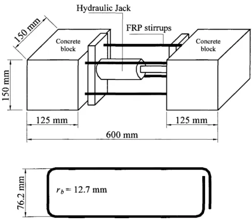
4.2.1.2 Bend strength of FRP stirrups 133
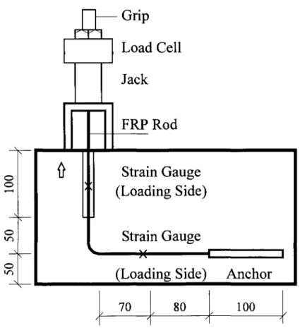
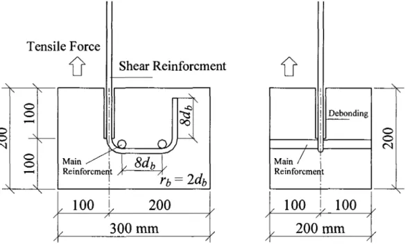
4.2.1.2.1 B.5 Method 135 4.2.1.2.2 B.12 Method 140
4.2.2 Steel bars 143 4.2.3 Concrete 144 4.3 Beam Specimens (Test Specimens) 146
4.4 Fabrication of Test Specimens 148
4.5 Instrumentation 161 4.6 Test Setup and Procedure 167
4.7 Summary 173
CHAPTER 5: TEST RESULS AND ANALYSIS 174
5.1 General 174 5.2 Test Results 174
5.2.1 Deflection 175 5.2.2 Flexural strains 175 5.2.3 Shear cracking load 178 5.2.4 Capacity and mode of failure 181
5.2.5 Cracking pattern and crack spacing 191
5.2.6 Strains in FRP stirrups 195 5.2.7 Effect of FRP stirrup spacing 205
5.2.8 Shear crack width 216 5.2.9 Serviceability limits 221 5.2.10 Effect of bend strength on the design shear capacity 223
5.3 Summary 225
CHAPTER 6: ANALYTICAL STUDY 227
6.1 General 227 6.2 Predictions using Design Codes and Guidelines 227
6.3 Predictions using MCFT 238 6.4 Shear Friction Model (SFM) 246 6.5 Unified Shear Strength Model 255 6.6 Theoretical Predictions of the Shear Crack Width 267
6.7 Summary 268
CHAPTER 7: SUMMARY AND CONCLUSIONS 271
7.1 Summary 271 7.2 Conclusions 273
7.2.1 FRP stirrup characterisation 273 7.2.2 FRP stirrup in beam specimens 273
7.2.3 Code predictions 276 7.2.4 Analytical investigation 277 7.3 Recommendations for Future Work 278
LIST OF FIGURES
CHAPTER 1
Figure 1.1: Kinking of the innermost fibres at the bend zone of FRP stirrups 2 Figure 1.2: Effect of bend strength of FRP stirrups on the shear strength of beam
specimen 3
CHAPTER 2
Figure 2.1: Shear resistance component in a cracked concrete beam without shear
reinforcement 10 Figure 2.2: Flexural and diagonal tension cracks (Winter and Nilson 1979) 11
Figure 2.3: Effect of shear span-to-depth ratio {aid) on shear strength of beams
without shear reinforcement (MacGregor 1997) 12 Figure 2.4: Modes of failure of deep beams (ASCE-ACI1973) 13 Figure 2.5: Modes of failure of short shear spans with aid ranging from 1.5 to 2.5
(ASCE-ACI 1973) 14 Figure 2.6: Typical shear failure of a slender beam 14
Figure 2.7: Internal forces in a cracked concrete beam with stirrups (ASCE-ACI 1973) 16
Figure 2.8: Ritter and Morsch's truss models 22 Figure 2.9: Equilibrium consideration for 45° truss (Collins and Mitchell 1997) 23
Figure 2.10: Equilibrium conditions for variable-angle truss (Collins and Mitchell 1997) 25
Figure 2.11: Compression field theory aspects (Mitchell and Collins 1974) 28 Figure 2.12: Modified compression field theory aspects (Vecchio and Collins 1986) 31
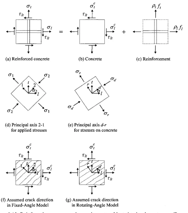
Figure 2.13: Reinforced concrete membrane elements subjected to in-plane stresses
(Pang and Hsu 1996) 37 Figure 2.14: Reinforced concrete element: (a) Reinforcement and loading conditions;
and (b) Mohr's circle for average stresses in concrete (Vecchio 2000) 42 Figure 2.15: Equilibrium conditions: (a) External conditions; (b) Perpendicular to crack
direction; (c) Parallel to crack direction; and (d) Along crack surface
Figure 2.16: Compatibility conditions: (a) Deformations due to average (smeared) constitutive response; (b) Deformations due to local rigid body slip along
crack; and (c) Combined deformations (Vecchio 2000) 45 Figure 2.17: Shear friction model in a concrete beam by Kriski and Loov (1996) 48
Figure 2.18: Rankine's failure criteria for reinforced concrete (Chen 1982) 50 Figure 2.19: Critical sections and strain distribution of a cracked beam (Park et al. 2006) 52
CHAPTER 3
Figure 3.1: Typical FRP products (fib 2006) 67 Figure 3.2: Typical stress-tensile strain of FRPs compared to steel 69
Figure 3.3: Test setup and specimen dimension tested by Maruyama et al. (1993) 72 Figure 3.4: The relationship between the tensile and bend strengths
(Maruyama et al. 1993) 73 Figure 3.5: Relationship between bend and concrete strengths (Maruyama et al. 1993) 73
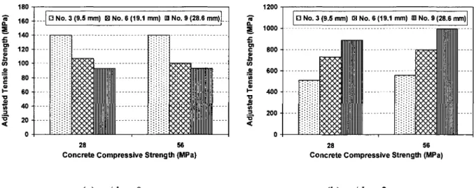
Figure 3.6: The test specimens for bend strength evaluation by Nagasaka et al. (1993) 74 Figure 3.7: Specimen details, test setup, and tested stirrups by Currier et al. (1994) 75 Figure 3.8: Details of the test specimens for hooked bars (Ehsani et al. 1995) 76 Figure 3.9: Influence of hook radius on load-slip relation (Ehsani et al. 1995) 76 Figure 3.10: Influence of concrete compressive strength on tensile strength
(Ehsani etal. 1995) 77 Figure 3.11: Effect of tail length and straight embedment length on tensile force at failure
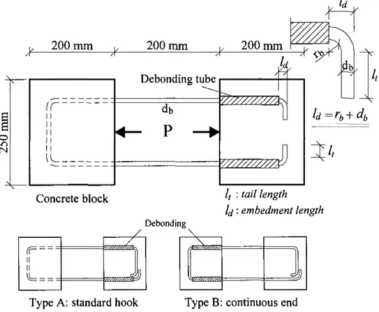
(Ehsani etal. 1995) 77 Figure 3.12: Test specimen and setup details (Ueda et al. 1995 & Ishihara et al. 1997) 79
Figure 3.13: Model of FRP bent bar in concrete by Nakamura and Higai (1995) 81 Figure 3.14: Details of the test specimens for evaluating the bend strength (Morphy 1999)...82
Figure 3.15: CFRP U-shaped stirrups for Phase I (El-Sayed et al. 2007) 84 Figure 3.16: Details of the test specimens (Guadagnini et al. 2007) 87 Figure 3.17: Average of maximum stress: (a) Type 2; and (b) Type 3
(Guadagnini et al. 2007) 88 Figure 3.18: Testing FRP rod at crack intersection by Kanematsu et al. (1993) 89
Figure 3.20: Comparison between the proposed equation results and experimental results
(Nakamura and Higai 1995) 91 Figure 3.21: Effect of the inclined crack on the FRP stirrup, Kinking effect,
(Morphy 1999) 92 Figure 3.22: Details of the test specimens for evaluating the kinking effect (Morphy 1999). .92
Figure 3.23: Test specimens and loading setup by Nagasaka et al. (1993) 95 Figure 3.24: Configuration of test specimens by Tottori and Wakui (1993) 97 Figure 3.25: Details of test specimens for shear by Yonekura et al. (1993) 98
Figure 3.26: Details of test specimens (Zhao et al. 1995) 99 Figure 3.27: Stirrup strain distribution model (Zhao et al. 1995) 100
Figure 3.28: Configuration of FRP Stirrups (Shehata 1999) 107 Figure 3.29: Details of beam specimens (Shehata 1999) 108 Figure 3.30: Beam specimens and instrumentations by Gudagnini et al. (2003 & 2006) 110
CHAPTER 4
Figure 4.1: Surface configuration of the carbon and glass FRP stirrups 132 Figure 4.2: Details of the FRP and steel stirrups: (a) FRP stirrups; and (b) Steel stirrups... 132
Figure 4.3: Typical tension testing of FRP straight portions: (a) Test setup;
and (b) Typical fibre-rupture of FRP straight portions 134 Figure 4.4: Typical stress-strain relationship for the reinforcing bars 135 Figure 4.5: Dimensions of the C-and U-shaped specimens for B.5 and B.12 methods 136
Figure 4.6: Schematic for B.5 method and specimen configuration 137 Figure 4.7: Attaching the debonding tubes to the FRP stirrups 137
Figure 4.8: Casting of the concrete blocks 138 Figure 4.9: Testing FRP stirrups in concrete blocks 139
Figure 4.10: Rupture of the FRP stirrup at the corner in concrete blocks followed
by stirrup slippage 139 Figure 4.11: Schematic for B.12 test method 141
Figure 4.12: Preparing No. 10 CFRP and GFRP U-specimens for B.12 test 141
Figure 4.13: Testing U-shaped FRP specimens using B.12 method 142 Figure 4.14: Typical fibre-rupture failure mode at the bend for U-shaped FRP specimens... 142
Figure 4.15: Typical tension testing of steel bars: (a) Test setup;
and (b) Failure of steel bars 143 Figure 4.16: Slump test of the fresh concrete before casting 144
Figure 4.17: Compression test of the standard concrete cylinders 145 Figure 4.18: Splitting test of the standard concrete cylinders 145 Figure 4.19: Stress-strain relationship for different concrete batches 146
Figure 4.20: Cross section of the New England Bulb Tee (NEBT) beams 147
Figure 4.21: Geometry and dimension of beam specimens 149 Figure 4.22: Reinforcement details and stirrup instrumentation of SC-9.5-2 151
Figure 4.23: Reinforcement details and stirrup instrumentation of SC-9.5-3 152 Figure 4.24: Reinforcement details and stirrup instrumentation of SC-9.5-4 153 Figure 4.25: Reinforcement details and stirrup instrumentation of SG-9.5-2 154 Figure 4.26: Reinforcement details and stirrup instrumentation of S4-9.5-3 155 Figure 4.27: Reinforcement details and stirrup instrumentation of SG-9.5-4 156 Figure 4.28: Reinforcement details and stirrup instrumentation of SS-9.5-2 157
Figure 4.29: Assembling the reinforcing cage of a beam specimen 159 Figure 4.30: Completed reinforcing cage and the formwork ready for casting 159
Figure 4.31: Concrete casting of abeam specimen 160 Figure 4.32: A concrete beam specimen just after casting and adjusting the surface 160
Figure 4.33: Curing of the beam specimens 161 Figure 4.34: Locations of the longitudinal reinforcement strain gauges for
the test specimens 163 Figure 4.35: Steel strands after attaching the strain gauges 164
Figure 4.36: CFRP stirrups instrumented with strain gauges 164
Figure 4.37: Deflection measurement using LVDTs 165 Figure 4.38: The demec gauges installed in both shear spans of each beam 165
Figure 4.39: Measuring the demec gauges using the digital extensometer 166 Figure 4.40: The data acquisition systems utilized in beam testing 166 Figure 4.41: Schematic for the setup used for testing the beams reinforced
Figure 4.42: Schematic for the setup used for testing the beams reinforced with GFRP
and steel stirrups 169 Figure 4.43: A photograph of the test setup for the beams reinforced with CFRP stirrups. ..170
Figure 4.44: A photograph of the test setup for the beams reinforced with GFRP stirrups. ..171 Figure 4.45: Measuring the initial shear crack widths using the hand-held microscope 172
Figure 4.46: Measuring the shear crack widths using high accuracy LVDTs 172
CHAPTER 5
Figure 5.1: Applied shear-deflection relationship for beams reinforced with
CFRP stirrups 176 Figure 5.2: Applied shear-deflection relationship for beams reinforced with
GFRP stirrups 176 Figure 5.3: Flexural strains of beam reinforced with CFRP stirrups 177
Figure 5.4: Flexural strains of beam reinforced with GFRP stirrups 177 Figure 5.5: Evaluating the shear cracking loads of the tested beams 179
Figure 5.6: Shear failure of beam SC-9.5-2 (CFRP@o?/2) 182 Figure 5.7: Shear failure of beam SC-9.5-3 (CFRP@tf/3) 183 Figure 5.8: Flexure failure of beam SC-9.5-4 (CFRP@J/4) 184 Figure 5.9: Shear failure of beam SG-9.5-2 (GFRP@rf/2) 185 Figure 5.10: Shear failure of beam SG-9.5-3 (GFRP@c//3) 186 Figure 5.11: Shear failure of beam SG-9.5-4 (GFRP@c//4) 187 Figure 5.12: Shear failure of control beam SS-9.5-2 (steel@d/2) 188 Figure 5.13: Load carrying capacity of beams reinforced with CFRP stirrups 189
Figure 5.14: Load carrying capacity of beams reinforced with GFRP stirrups 190 Figure 5.15: Effect of the shear reinforcement stiffness on the beams strength 190 Figure 5.16: Crack pattern at failure for beams reinforced with CFRP stirrups 192 Figure 5.17: Crack pattern at failure for beams reinforced with GFRP stirrups 193 Figure 5.18: Crack pattern at failure for the control beam SS-9.5-2 (steel@c//2) 194
Figure 5.19: Shear crack spacing versus stirrups spacing relationship 194 Figure 5.20: Typical applied shear force-stirrup strain relationship
Figure 5.21: Typical applied shear force-stirrup strain at the bend of FRP stirrups
(SC-9.5-2) 196 Figure 5.22: Comparisons between the average stirrup strains calculated from both
shear spans of beams reinforced with CFRP stirrups 197 Figure 5.23: Applied shear force-average stirrup strain for beams with CFRP stirrups 199
Figure 5.24: Applied shear force-average stirrup strain for beams with GFRP stirrups 199 Figure 5.25: Comparison between the average stirrup strains for FRP stirrups with similar
stirrups spacing: (a) spacing=d/2; (b) spacing -dll>; and (c) spacing=d/4 200 Figure 5.26: Effect of the stiffness of the shear reinforcement on the average stirrup strain. 202 Figure 5.27: Applied shear force-maximum stirrup strain relationships for CFRP
stirrups in beam specimens comparing to the steel stirrup 203 Figure 5.28: Applied shear force-maximum stirrup strain relationships for GFRP
stirrups in beam specimens comparing to the steel stirrup 203 Figure 5.29: Stirrup strain distribution along the shear span of
SC-9.5-2 beam (CFRP@rf/2) 206 Figure 5.30: Stirrup strain distribution along the shear span of
SC-9.5-3 beam (CFRP@<//3) 207 Figure 5.31: Stirrup strain distribution along the shear span of
SC-9.5-4 beam (CFRP@<//4) 208 Figure 5.32: Stirrup strain distribution along the shear span of
SG-9.5-2 beam (GFRP@<//2) 209 Figure 5.33: Stirrup strain distribution along the shear span of
SG-9.5-3 beam (GFRP@J/3) 210 Figure 5.34: Stirrup strain distribution along the shear span of
SG-9.5-4 beam (GFRP@<//4) 211 Figure 5.35: Effect of stirrup spacing on effective capacity of FRP stirrups
in beam action 212 Figure 5.36: Comparison of effective capacity of CFRP stirrups in beam action 212
Figure 5.37: Shear resisting components of beams reinforced with CFRP stirrups 214 Figure 5.38: Shear resisting components of beams reinforced with GFRP stirrups 214
Figure 5.39: Comparison between the shear resisting components for FRP stirrups in beams with similar stirrups spacing: (a) spacing=<i/2; (b) spacing
=d/3; and(c) spacing=t//4 215
Figure 5.40: Applied shear force-shear crack width relationships for beam
specimens reinforced with GFRP stirrups: (a) SG-9.5-2; (b) SG-9.5-3;
and (c) SG-9.5-3 218 Figure 5.41: Maximum shear crack width for beams reinforced with CFRP stirrups 219
Figure 5.42: Maximum shear crack width for beams reinforced with GFRP stirrups 219 Figure 5.43: Comparison between the maximum shear crack width for beams
reinforced with FRP stirrups at the same spacing: (a) spacing=J/2;
(b) spacing =d/3; and (c) spacing-J/4 220 Figure 5.44: Applied shear force-maximum stirrup strain across the critical shear
crack-serviceability requirements 222
CHAPTER 6
Figure 6.1: Predicted shear strength of beams reinforced with CFRP stirrup 231 Figure 6.2: Predicted shear strength of beams reinforced with GFRP stirrup 231 Figure 6.3: Comparison between measured and predicted shear strength 232 Figure 6.4: Experimental to predicted shear strength using JSCE (1997)
and CSA (2006) 236 Figure 6.5: Experimental to predicted shear strength using ACI (2006)
and CSA (2009) 237 Figure 6.6: Experimental to predicted shear strength using CNR DT-203 (2006) 238
Figure 6.7: Measured shear strength versus the predicted using the MCFT 239 Figure 6.8: Effect of stirrup spacing of the effective FRP stirrup capacity using MCFT. ...240
Figure 6.9: Comparison between measured average stirrup strain and the
predicted using the MCFT for beams reinforced with CFRP stirrups 241 Figure 6.10: Comparison between measured average stirrup strain and the
predicted using the MCFT for beams reinforced with GFRP stirrups 242 Figure 6.11: Measured shear crack width versus predicted using MCFT for
Figure 6.12: Measured shear crack width versus predicted using MCFT
for beams reinforced with CFRP stirrups 244 Figure 6.13: Measured shear crack width versus predicted using MCFT
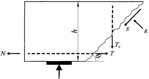
for beams reinforced with GFRP stirrups 245 Figure 6.14: Internal forces at a potential failure plane using SFM 248
Figure 6.15: Potential failure planes for beams reinforced with CFRP stirrups for
SFM analysis 249 Figure 6.16: Potential failure planes for beams reinforced with GFRP stirrups for SFM
analysis 250 Figure 6.17: Measured shear strength versus predicted using SFM 254
Figure 6.18: Effect of stirrup spacing of the effective CFRP stirrup stress using SFM 254
Figure 6.19: Predicted shear strength according to the strain-based analysis 261
Figure 6.20: Predicted shear strength according to the JSCE (1997) 262 Figure 6.21: Predicted shear strength according to the CSA (2002) 263 Figure 6.22: Predicted shear strength according to the ACI (2006) 264 Figure 6.23: Predicted shear strength of beam specimens using the unified shear model 266
Figure 6.24: Prediction of shear crack width for the control beam (SS-9.5-2)
using Equation (6.8) 267 Figure 6.25: Prediction of shear crack width for beams reinforced with CFRP stirrups
using the proposed equation (Equation 6.9) 269 Figure 6.26: Prediction of shear crack width for beams reinforced with CFRP stirrups
LIST OF TABLES
CHAPTER 2
Table 2.1: Values of 6 and /? for sections with transverse reinforcement
(AASHTO LRFD 2004) 62 Table 2.2: Values of 6 and ft for sections with less than minimum transverse
reinforcement (AASHTO LRFD 2004) 63
CHAPTER 3
Table 3.1: Mechanical properties of the most commonly used fibres
(ISIS Canada 2007) 66 Table 3.2: Typical properties of thermosetting resins (ISIS Canada 2007) 68
Table 3.3: Typical mechanical properties of FRP reinforcing bars (ISIS Canada 2007) 68
Table 3.4: Designation of some FRP reinforcing bars (ISIS Canada 2006) 70 Table 3.5: Details and test results of CFRP stirrups embedded in concrete blocks
(Phase II) (El-Sayed et al. 2007) 86
CHAPTER 4
Table 4.1 Table 4.2 Table 4.3
The test results of FRP straight portions 135 The bend strength of FRP C- and U-shaped stirrups 140
Concrete properties and reinforcement details of test specimens 150
CHAPTER 5
Table 5.1: Summary of the test results 180 Table 5.2: The stress at the bend zone of FRP stirrups corresponding to an
average strain equals 4000 microstrain in the straight portions 224
CHAPTER 6
Table 6.1 Table 6.2 Table 6.3
Predicted shear strength of test specimens 233 Shear strength prediction of beams reinforced with FRP stirrups 234
Table 6.4: Strain-based calculated shear strength for FRP RC beams without
stirrups in comparison to the experimental results 257 Table 6.5: The predicted shear strength of the beam specimens using the unified
CHAPTER 1
INTRODUCTION
1.1 Background and Problem Definition
Corrosion of steel reinforcement is a major cause of deterioration in reinforced concrete structures especially those exposed to harsh environmental conditions such as bridges, concrete pavements, and parking garages. The use of concrete structures reinforced/prestressed with fibre-reinforced polymer (FRP) composite materials has been growing to overcome the common problems caused by corrosion of steel reinforcement and to increase the anticipated service life of such structures. The climatic conditions may have a hand in accelerating the corrosion process where large amounts of salts are used for ice removal during the winter season. These conditions normally accelerate the need of costly repairs and may lead, ultimately, to catastrophic failure. Therefore, using non-corrodible FRP materials as an alternative reinforcement in prestressed and reinforced concrete structures is becoming a more accepted practice in structural members subjected to severe environmental exposure. This, in turn, eliminates the potential of corrosion and the associated deterioration.
Stirrups for shear reinforcement normally enclose the longitudinal reinforcement and are thus the closest reinforcement to the outer concrete surface. Consequently, they are more susceptible to severe environmental conditions and may be subjected to related deterioration which reduces the service life of the structure. Thus, replacing the conventional stirrups with the non-corrodible FRP ones is a promising aspect to provide more protection for structural members subjected to severe environmental exposure. However, from the design point of view, the direct replacement of steel with FRP bars is not possible due to various differences in the mechanical properties of the FRP materials compared to steel. These differences include higher tensile strength, the lower modulus of elasticity, the different bond characteristics, and the absence of yielding plateau in the stress-strain relationships of FRP materials. Extensive research programs have been conducted to investigate the flexural behaviour of concrete members reinforced with FRP reinforcement (Benmokrane et al. 1996; El-Salakawy et al. 2003; El-Salakawy and Benmokrane 2004; Gravina and Smith 2008). On the other hand, the use of FRP as shear reinforcement (stirrups) for concrete members has not been adequately
explored to provide a rational model and yield satisfactory guidelines to predict the shear strength of concrete members reinforced with FRP stirrups.
FRP bars are made of anisotropic materials with weak lateral strength compared to their longitudinal one. Bending FRP bars to form stirrups significantly reduces the strength at the bend portions (Maruyama et al. 1993; Ishihara et al. 1997; Shehata 1999; El-Sayed et al. 2007; Ahmed et al. 2008). The strength reduction of the FRP stirrups was referred to as the bending effect rather than the kinking effect (Morphy 1999; Shehata 1999). At the bend, the stirrup resists lateral loads due to bearing against concrete, in addition to the stresses in their longitudinal direction parallel to the fibre's direction. Besides, bending the FRP bars causes the innermost fibres at the bend to be kinked compared to those at the outermost radius as shown in Figure 1.1. The intrinsic weakness of fibres perpendicular to their axis accompanied by the kinked fibres at the bend contributes to reduced strength at the bend portion of FRP stirrups compared to straight bars. The bend capacity of FRP bars is influenced by bending process, bend radius, r^, bar diameter, db, and type of reinforcing fibres (ACI 2006). Moreover, the shear strength of concrete beams reinforced with FRP stirrups may be governed by the reduced bend strength of the FRP stirrups, especially when diagonal shear cracks intersect the FRP stirrups at the bend zone as shown in Figure 1.2.
S Type 1
\
vi
(a) Bare fibres after removing the resin (b) Fibre's orientation at the bend
i
FRP Stirrups ( • • • • * • • Bend Effect ' Figure 1.2: Effect of bend strength of FRP stirrups on the shear strength of beam specimen.The FRP reinforcement is characterised by a linear elastic stress-strain relationship up to failure. The shear failure of a concrete member reinforced with FRP stirrups occurs due to either rupture of the FRP stirrups or to crushing of concrete in the compression zone. Failure due to FRP stirrup rupture is more brittle than shear compression failure and occurs suddenly when; at least, one of the FRP stirrups crossing the critical shear crack reaches its strength capacity. This is contrary to steel stirrups when yielding of steel provides a more ductile failure. When FRP stirrups are used as shear reinforcement, serviceability limits (cracking and deflection) and have to be checked because of the lower modulus of elasticity of the FRP materials in comparison with the steel. Although there is no limit for the shear crack width at service, there are few recommended strain limits for the FRP stirrups at service and ultimate which need to be verified. Moreover, the shear capacity of concrete sections reinforced with FRP stirrups are unduly underestimated by some design codes and guidelines.
Recently, there have been a variety of commercially available FRP stirrups with bend strength equal to almost to double the yield stress of the conventional steel bars. The characterisation of these stirrups was determined through testing of C- and U-shaped FRP stirrups in accordance with B.5 and B.12 (ACI 2004) test methods (El-Sayed et al. 2007; Ahmed et al. 2008). However, the behaviour of these stirrups in beam specimens is still to be investigated.
Based on the results from the literature and the aforementioned discussion, it is obvious that the shear behaviour of concrete beams reinforced with FRP stirrups differs from
that reinforced with steel stirrups. Limited research has been conducted to quantify the contribution of the FRP stirrups to the shear carrying capacity. However, the full response is still in need to be completely understood. Therefore, the shear behaviour of concrete beams reinforced with FRP stirrups is investigated through this research thesis.
1.2 Objectives and Originality
The use of FRP as reinforcement for concrete structures is rapidly increasing and it is now being intensively researched as primary reinforcement for concrete. These efforts reflect the urgent need for completely understanding the behaviour of FRP reinforced concrete elements. However, limited research work has been carried out to investigate the shear behaviour of the FRP-reinforced. Through the NSERC Research Chair in Innovative FRP Composites for Infrastructures at the University of Sherbrooke, the shear behaviour of FRP reinforced concrete members is being investigated. The investigation was initiated by evaluating the concrete contribution of FRP-reinforced concrete beams (El-Sayed 2006). Thereafter, the current study evaluates the contribution and the structure performance of the FRP stirrups as shear reinforcement for concrete beams.
Many design codes and guidelines addressing the FRP as primary shear and flexural reinforcement have been recently published. The shear design provisions incorporated in these codes and guidelines are based on modifying the original equations used for steel reinforced concrete sections to account for the substantial difference between FRP and steel reinforcement. Thus, investigations are needed to examine the validity of these methods. The main objectives of this investigation are:
1. To investigate the structural performance of FRP stirrups as shear reinforcement for concrete members.
2. To investigate the shear behaviour of concrete beams reinforced with FRP stirrups and to evaluate the contribution of the FRP stirrups, V„f, to the shear resistance.
3. To evaluate the validity of the current analytical and design approaches for shear strength in the design codes and guidelines for concrete members reinforced with FRP stirrups.
4. To establish design recommendations for the concrete members reinforced with FRP stirrups.
1.3 Methodology
To achieve the aforementioned objectives, experimental and analytical programs were designed. The experimental program included constructing and testing of seven large-scale T-beams reinforced longitudinally with steel strands and transversally with FRP and steel stirrups. These beams were designed to study the effect of the material type and spacing of FRP stirrups on the shear behaviour and strength compared to the steel ones. The beam specimens were divided into two groups concerning the FRP stirrup materials in addition to a control beam reinforced with steel stirrups. The first group included three beams reinforced with carbon FRP stirrups with three different stirrup spacing. The second group was reinforced with GFRP stirrups with the same spacing in group one. The control beam reinforced with steel stirrups was selected for comparison, when applicable. The test parameters were the shear reinforcement type (CFRP, GFRP, and steel stirrups), the shear reinforcement ratio (0.262 to 0.526%), and the stirrup spacing (150 to 300 mm).
The analytical investigation included analysis of the test results using the different available shear design provisions pertinent to structural members reinforced with FRP stirrups. The results of each beam specimen were compared to the predicted values using different design codes and guidelines. Based on the comparisons and experimental findings, a revised value for the FRP stirrup strain at service was proposed. The analytical investigation included also theoretical prediction of the shear crack width and a simple equation for predicting the shear crack width of concrete beams reinforced with FRP stirrups was proposed. The proposed equation was based on modifying the equation proposed by Placas and Regan (1971) to account for FRP stirrups instead of steel ones. The analytical investigation extended to include the analysis of the beam specimens using well defined shear theories including the modified compression field theory (MCFT), the shear friction model (SFM) and the recently published unified shear strength model (USSM). The results of these methods were compared to the experimentally measured values and the main findings were verified.
1.4 Structure of the Thesis
The thesis is divided into seven chapters. The following is a brief description of each chapter's content:
Chapter 1: This chapter defines the problem and presents the main objectives of this
investigation. The originality and methodology followed to achieve the objectives of this research program is also highlighted.
Chapter 2: This chapter provides a review of the shear behaviour of reinforced concrete
beams either with or without shear reinforcement. This chapter also includes background and review on the analytical methods and theories predicting the shear strength and behaviour of concrete beams reinforced with conventional steel bars. The shear design provisions available in North America are also presented and discussed.
Chapter 3: This chapter provides brief information on the FRP composite materials and their
characteristics. The available literature review focusing on the effect of the bend on the FRP stirrup strength and the behaviour of concrete beams reinforced with FRP stirrups are also presented in this chapter. The available shear design provisions for concrete members reinforced with FRP composite materials recently published in Japan, Europe, Canada and USA are also introduced and discussed.
Chapter 4: This chapter describes the experimental program which included the construction
and testing of seven large-scale T-beams reinforced with FRP and steel stirrups. In this chapter, the geometry and reinforcement details of the test specimens, stirrup configuration, test setups and procedures, and the instrumentation details are presented. This chapter also provides detailed characteristics of the materials used in this research program.
Chapter 5: The results of the experimental investigation conducted in this research program
are presented in this chapter. The general behaviour of the tested beams is presented in terms of flexural strains, load-deflection response and mode of failure. The shear behaviour of the beams is also presented and discussed including shear cracking load, applied shear force-stirrup strains relationships, applied shear force-shear crack width relationships, shear cracking pattern, and the inclination angles of the major shear crack at failure (in case of shear failure). The analysis of the results includes the effect of different parameters on the shear response of beams reinforced with FRP stirrups such as, FRP stirrups material, shear
reinforcement ratio (stirrup spacing), and the bend strength of the FRP stirrups relative to the strength parallel to the fibre's direction. The serviceability issue regarding the FRP stirrups is also discussed and a stirrup strain limit at the service load limit is proposed to keep the shear crack width controlled.
Chapter 6: In this chapter, the shear strengths of the tested beams as well as 24 beams from
literature are predicted using shear design provisions in the available codes and guidelines and the predicted values are compared with the experimental ones to evaluate the accuracy of the design equations. The analytical study was extended to include the shear theories for predicting the shear behaviour of the tested beams. The full response of the tested beams was predicted using the modified compression field theory (MCFT). The shear strength of the tested beams was also calculated using the shear friction model (SFM) as well as the unified shear strength model (USSM). The proposed modifications were verified considering the tested beams in addition to 73 beams from literature. A simple equation for estimating the shear crack width in beams reinforced with FRP stirrups is also proposed in this chapter.
Chapter 7: This chapter presents the summary and conclusion of this investigation based on
the findings of the experimental and the analytical studies. Recommendations for future research work are also presented.
CHAPTER 2
SHEAR BEHAVIOUR OF CONCRETE BEAMS REINFORCED WITH
STEEL: BACKGROUND AND REVIEW
2.1 General
The flexural behaviour of reinforced and prestressed concrete has been extensively investigated and incorporated in many design codes with well-defined simple design equations. On contrary, the shear behaviour of reinforced and prestressed concrete beams is not completely understood despite of the extensive research work conducted in this area. This is related to the complexity of this phenomenon, which involves many variables that can not be simplified and rationalized into one model. Several models were introduced based on the experimental and theoretical investigations. Some of these methods were adopted by different codes and design procedures.
The shear failure of reinforced and prestressed concrete members is frequently sudden and brittle so that the design must ensure that the shear strength equals or exceeds the flexural strength at all points along the member. This is the main reason to consider the flexural design first to determine the cross-section and the flexural reinforcement. Therefore, concrete beams are generally reinforced with shear reinforcement to ensure that, upon on overloading, the flexural failure will occur rather than shear failure. Most of the shear design provisions divide the shear strength of the reinforced concrete members into two components: concrete contribution, Vc, and shear reinforcement contribution, Vs. The design shear strength is based
on the summation of both contributions considering appropriate factors of safety.
The shear behaviour of steel-reinforced concrete beams has been extensively investigated for decades and it is not reviewed because this is beyond the scope of this study. A comprehensive review on Shear and Diagonal Tension in concrete beams with/without shear reinforcement was provided by the Joint ASCE-ACI Task Committee 426 on Shear and Diagonal Tension in 1973 and updated by the Committee 445 on Shear and Torsion in 1998. However, this chapter presents a brief review on the shear behaviour of reinforced concrete beams with a focus on the role of shear reinforcement in concrete, mechanisms of shear transfer and modes of failure. The available analytical methods and design approaches for
shear in steel reinforced concrete are also reviewed in this chapter since some of the design approached for FRP reinforced concrete beams are based on these methods. Furthermore, a literature review on the shear behaviour and design provision of concrete beams reinforced with FRP bars is presented in Chapter 3.
2.2 Shear in Reinforced Concrete Beams without Shear Reinforcement
The shear behaviour of reinforced concrete beams without shear reinforcement has been extensively investigated. However, a well-understanding of shear behaviour of such beams is still limited. This is referred to the complexity and sensitivity of the affecting parameters that govern the shear strength of concrete beams without shear reinforcement.
2.2.1 Shear resisting mechanisms
The ASCE-ACI Committee 445 (1998) identified five components for shear transfer in cracked concrete beams. These five components are: (i) shear resistance provided by the uncracked concrete above the neutral axis; (ii) the interface shear transfer along the two faces of the cracks after the appearance of shear cracks, which is sometimes noted as "aggregate interlock;" (iii) dowel action of the longitudinal reinforcement; (iv) residual tensile stresses across the crack because a "clean crack" does not occur and there are some connecting bridges; and (v) arch action, which is significant in deep member with a shear span-to-depth ratio, a/d, less than 2.5. Generally the aforementioned five components are lumped together and referred to as concrete contribution to the shear strength, Vc. The shear resistance
components for a slender beam without shear reinforcement are shown in Figure 2.1.
2.2.2 Pattern of inclined cracking and modes of shear failure
When the principal tensile stress at any location exceeds the cracking strength of the concrete a crack forms. Cracks usually form perpendicular to the directions of the principal stress. For members with uniaxial stress the principal tress will be parallel to the longitudinal direction of the member resulting in parallel cracks perpendicular to the member's axis. For members subjected to biaxial stresses, as the case of flexural and shear stresses, the principal tensile stress will be inclined at an angle with the member's axis. Therefore, the shear cracks are usually inclined to the member's axis.
Vcz: Shear resisted y uncracked concrete Va : Shear transferred by aggregage interlock Vd : Dowel action
Vrt : Residual tensile stresses across the crack Vac: Arch action (in deep members)
Figure 2.1: Shear resistance component in a cracked concrete beam without shear reinforcement.
Winter and Nilson (1979) specified two different modes of shear cracks: web-shear cracks and flexure-shear cracks. When the flexural stresses are small at the particular location, the diagonal tension stresses are inclined at about 45° and are numerically equal to the shear stresses with a maximum at the neutral axis. Consequently, diagonal web-shear cracks start mostly near the neutral axis and then propagate in both directions as shown in Figure 2.2(a). The situation will be different when both shear forces and bending moments have large values. The flexural cracks will appear and their widths are controlled by the presence of longitudinal reinforcement. However, when the diagonal tension stress at the upper end of one or more of these cracks exceeds the tensile strength of the concrete, the crack bends in diagonal direction and continues to grow in length and width as shown in Figure 2.2(b). These cracks are known as flexure-shear cracks and more are common than web-shear cracks.
Large V and Small M
(a) Web-shear cracks
Large V and Large M
Flexural-shear cracks Flexural cracks
(b) Flexure-shear cracks
Figure 2.2: Flexural and diagonal tension cracks (Winter and Nilson 1979).
The behaviour of beams failing in shear varies widely depending on the relative contributions of beam action and arch action and the amount of shear reinforcement (MacGregor 1997). The moments and shears at inclined cracking and failure of a rectangular beam without shear reinforcement are shown in Figure 2.3. The shaded areas in the figure show the reduction in strength due to shear. Thus, the shear reinforcement is provided to achieve the full flexural capacity.
According to MacGregor (1997) classification, shown in Figure 2.3, the shear span can be classified based on shear span-to-depth ratio, aid, into four types:
a
v
1
v
aT
v
Deep (a) BeamT
V Very slender ^ Flexural capacity Inclined cracking and failure 1.0 2.5 a/d 6.5(b) Moment at cracking and failure
Shear failure
Flexural failure
Inclined cracking and failure
a/d
6.5
(c) Shear at cracking and failure
Figure 2.3: Effect of shear span-to-depth ratio (a/d) on shear strength of beams without shear reinforcement (MacGregor 1997).
1. Very short: with shear span to depth ratio, aid, equals 0 to 1.0. These beams develop inclined cracks joining the load and the support. The cracks, in turn, destroy the horizontal shear flow from the longitudinal steel to the compression zone and the behaviour changes from beam action to arch action. The failure of such beams, which is commonly referred to as deep beams, is shown in Figure 2.4.
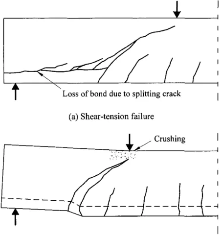
2. Short: with aid ranges from 1 to 2.5. These beams develop inclined cracks and after redistribution of internal forces are able to carry additional load, in part by arch action. The final failure of such beams will result from a bond failure, a splitting failure or a dowel failure along the tension reinforcement as shown in Figure 2.5(a) or by crushing of the compression zone over the shear crack as shown in Figure 2.5(b).
3. Slender: with aid ranges from 2.5 to about 6. In these beams the inclined cracks disturb the equilibrium to such an extent that the beam fails at inclined cracking as shown in Figure 2.6.
4. Very slender: with aid greater than about 6. These beams will fail in flexure prior to the formation of inclined cracks.
I Types of failure: 1: Anchorage failure 2: Bearing failure 3: Flexural failure 4,5: Crushing of compression strut
Loss of bond due to splitting crack i (a) Shear-tension failure
Crushing I
(b) Shear-compression failure
Figure 2.5: Modes of failure of short shear spans with aid ranging from 1.5 to 2.5 (ASCE-ACI 1973).
2.2.3 Factors affecting shear strength
For beams without shear reinforcement, the shear resisting capacity includes the five resisting mechanisms listed earlier. The shear resisting capacity (shear strength) is influenced by the following variables as introduced by the ASCE-ACI (1998):
1. The concrete tensile strength;
2. The longitudinal reinforcement ratio; 3. Shear span-to-depth ratio;
4. Axial forces; and
5. Depth of concrete members (size effect).
2.3 Shear in Reinforced Concrete Beams with Shear Reinforcement
The shear failure of the concrete beams is brittle and catastrophic in nature. This failure occurs without sufficient advance warning. Thus, the purpose of using shear reinforcement is to ensure that the full flexural capacity of the concrete member can be developed.
2.3.1 Internal forces in a concrete beam with shear reinforcement
The main purpose for providing shear reinforcement to a reinforced concrete element is to achieve its flexural capacity, minimize the shear deformation, and keep the element away from the brittle shear failure. The internal forces in a typical concrete beam reinforced with steel stirrups and intersecting a diagonal shear crack are shown in Figure 2.7(a). The shear is transferred across line A-B-C and consequently accumulate the following contributions: (i) the shear in the compression zone, Vcz\ (ii) the vertical component of the shear transferred across
the crack by interlock of the aggregate particles on the two faces of the diagonal crack, Vay\
(iii) the dowel action of the longitudinal reinforcement, Vj, and (iv) the shear transferred by tension in the stirrups, Vs. The loading history of such a beam is shown qualitatively in Figure
2.7(b). As shown in Figure 2.7(b) the summation of the internal shear resistance components must equal the applied shear force which is represented by the uppermost line. Prior to flexural cracking, all shear is carried by the uncracked concrete. Between flexural and inclined cracking, the external shear is resisted by Vcz, Vay, and Vj (the concrete components).
As soon as the inclined cracks appear, the stirrups resist a portion of the applied shear and noted as stirrup contribution, Vs. Eventually, the stirrups crossing the crack yield, and Vs
remains constant for higher applied shears. Once the stirrup yield, the inclined crack opens more rapidly. As the inclined crack widens, the aggregate interlocking component, Vay,
decrease further, forcing Vj and Vcz (dowel action and uncracked concrete contributions) to
increase at accelerated rate until either splitting (dowel) failure occurs or the compression zone fails due to combined shear and compressive stresses.
A
T
R(a) Shear resisting mechanisms.
Dowel splitting Flexural Inclined cracking cracking Yield of Failure stirrups Applied shear
(b) Distribution of internal shear.
Each of three aforementioned shear resisting components of this process except Vs has
a brittle load-deflection response. As a result it is difficult to quantify the contribution of Vcz,
Vay, and Vd at ultimate. In design, these are lumped together as Vc referred to as "the shear
carried by concrete". Thus the nominal shear strength, V„, is assumed to be as follows:
V„=VC+VS (2.1)
Traditionally in North American design practice, Vc, is taken equal to the shear force at
the initiation of inclined shear cracking, Vcr, which approximately equals the ultimate shear
strength of slender concrete beams without stirrups.
2.3.2 Role of shear reinforcement in concrete beams
Prior to diagonal cracking, the strain in the stirrups is equal to the corresponding strain in surrounding concrete. The stresses in the stirrups prior to diagonal cracking will not exceed 20 to 40 MPa (MacGregor 1997). Winter and Nilson (1979) reported that there is no noticeable effect for the shear reinforcement prior to the formation of diagonal cracks and the shear reinforcement could be free of stress until the diagonal cracking. Thus, the stirrups do not prevent the appearance of the diagonal cracks; they come into play only after the cracks have formed. The stirrups enhance to the shear performance of a beam, in addition to their contribution to the shear strength, Vs, by the following means:
1. Improve the contribution of the dowel action. The stirrups effectively support the longitudinal reinforcement that crossing the flexural shear cracks close to the stirrup. 2. Control the widths of the diagonal shear cracks and, in turn, maintain the contribution
provided by the aggregate interlock.
3. Confine the cross section when closely spaced stirrups are used. This increases the compressive strength of the concrete and enhances the zones affected by the arch action.
4. Enhance the bond and prevent the breakdown when splitting cracks develop in anchorage zone due to dowel forces.
It can be summarized that the shear reinforcement in concrete beam maintain the overall integrity of the concrete contribution, Vc, allowing the development of additional shear
2.3.3 Modes of shear failure
There are various modes of failure that can be observed in concrete beams reinforced with shear reinforcement. These modes of failure can be summarized as:
1. Failure of shear reinforcement (stirrups). When the steel stirrups reaches their yield stress, the shear crack widths get wider resulting in breakdown of the aggregate interlocking. Consequently, the beam fails in shear due to crushing or shearing of the compression zone above the neutral axis.
2. Failure due to crushing of the beam web. This failure mode usually happens either when the beam has thin web that may crush due to inclined compressive strength or when the beam is provided with very high shear reinforcement ratio.
3. Failure of the stirrups anchorage. The functionality of the stirrups depends on their mechanical anchorage. Loosing the anchorage before stirrup yielding will cause a sudden failure of the beam without achieving the stirrup capacity.
4. Failure of the flexural reinforcement. The shear cracking yields more tensile stresses in the flexural reinforcement which may lead to yielding of the longitudinal reinforcement or anchorage failure.
5. Failure to meet the serviceability requirements. However, there is no specific shear crack width specified in the design codes, but the larger shear crack widths at service load my not be accepted.
2.4 Shear Strength Analysis of Reinforced Concrete Beams
The manner in which the shear failures occur varies widely depending on the dimensions, geometry, loading and properties of the members. For this reason, there is no unique way to design for shear (MacGregor 1997). Moreover, for complex phenomena influenced by many variables understanding the meaning of particular experiments and the range of applicability of the results is extremely difficult unless the research is guided by an adequate theory which can identify the important parameters (Collins et al. 2007). Several attempts have been made to rationalize the shear design procedures for reinforced and prestressed concrete members decades ago. Some of these procedures were reviewed in the ASCE-ACI Committee 426 (1973) report. Recently, the ASCE-ACI Committee 445 (1998) has published an updated report reviewing some of the shear models developed for concrete members. This section

![Figure 2.16 summarizes the compatibility conditions of the DSFM. The apparent inclination of the apparent principal strains ([e] = \£ x s y y xy }) will be calculated as:](https://thumb-eu.123doks.com/thumbv2/123doknet/5408252.126192/68.899.195.714.98.653/summarizes-compatibility-conditions-apparent-inclination-apparent-principal-calculated.webp)