O
pen
A
rchive
T
OULOUSE
A
rchive
O
uverte (
OATAO
)
OATAO is an open access repository that collects the work of Toulouse researchers and
makes it freely available over the web where possible.
This is an author-deposited version published in :
http://oatao.univ-toulouse.fr/
Eprints ID : 19648
To cite this version : Bhat, Shantanu Shrinath and Zhao, Jisheng and
Lo Jacono, David
and Sheridan, John and Hourigan, Kerry and
Thompson, Mark C. Effect of Central Body Size on the Leading Edge
Vortex of a Rotating Insect Wing. (2016) In: 20th Australasian Fluid
Mechanics Conference, 5 December 2016 - 8 December 2016 (Perth,
Australia). (Unpublished)
Any correspondence concerning this service should be sent to the repository
administrator:
[email protected]
Effect of Central Body Size on the Leading Edge Vortex of a Rotating Insect Wing
S. S. Bhat1, J. Zhao1, D. L. Jacono2, J. Sheridan1, K. Hourigan1and M. C. Thompson1 1Fluids Laboratory for Aeronautical and Industrial Research (FLAIR)
Department of Mechanical and Aerospace Engineering Monash University, Victoria 3800, Australia 2Institut de M ´ecanique des Fluides de Toulouse (IMFT)
CNRS, UPS, Universit de Toulouse, Alle Camille Soula, F-31400, Toulouse, France
Abstract
The stable attachment of a leading-edge vortex (LEV) is respon-sible for the high lift observed from insect wings. In experi-ments, we study the flow structure over a model wing mounted on a central body. The diameter of the central body and the change in Rossby number (Ro) due to placement of the wing root away from the centre can affect the flow structure. Nor-mally, the LEV splits to form dual LEVs in a rotating wing, with the spanwise split location changing with Reynolds num-ber. The results presented here show that the LEV structure is minimally affected by changes in the central body size for a wide range of body sizes.
Introduction
The flapping motion of the wings of natural flyers, such as in-sects, remains a topic of interest to biophysicists and engineers. The aerodynamics of the insect wing motion has been studied by a number of researchers including [17, 16, 5, 4, 11]. Sev-eral mechanisms have been proposed to explain the higher lift observed in insect wings flapping at very high angles of attack (α ∼ 45◦). The stable attachment of the leading-edge vortex (LEV), proposed by [6] is considered to be the most important mechanism.
The flapping motion of an insect wing is comprised of two strokes, the upstroke and downstroke. The insect wing rotates at nearly constant angle of attack with a constant angular velocity during the major portion of a stroke, called the rotational trans-lation. Towards the end of the stroke, the wing decelerates and flips its orientation to start the reverse stroke. During the rota-tional translation, the fluid separated from the leading edge rolls up on the suction side of the wing forming an LEV. The LEV is spiral in nature, growing in size from the wing-root towards the wing-tip [2].
The LEV formation and its stability can be affected by sev-eral parameters, including the wing aspect ratio (A), Reynolds number (Re), wing flexibility and wing shape. Numerical and experimental studies have shown the effects of these parame-ters on the LEV [14, 15, 7, 18, 3]. However, some differences in the flow structures have been observed between the numerical and experimental studies. These differences could be attributed to the differences in the geometries of the models used for the study.
Some of the numerical studies, such as those by [1], have mod-elled the full insect with both the wings, whereas other numeri-cal studies, such as those by [8], have modelled an isolated wing without the insect body. The recent studies by [10] and [13] have shown the effects of wing-body interaction on the flow structure. They observed the differences between the models with and without the insect body and concluded that the total lift production increases in presence of the insect body.
Experimental models require a central shaft and a connecting rod to hold and rotate the wing. As a consequence, the central body size and the radius of gyration of the wing can affect the LEV formation and its growth. Lentick and Dickinson [12] have proposed that the rotational accelerations stabilise the LEVs on rotating wings. In experiments, with a change in the length of the connecting rod, the radius of gyration changes; resulting in a change in the rotational accelerations. Wolfinger and Rockwell [19] have systematically varied the radius of gyration and found that the vortex system degrades rapidly with an increase in the rotational acceleration.
Unlike the numerical wing-body interaction studies, the central body in experiments also rotates with the wing. The central body size directly influences not only the radius of gyration, but also the secondary flow that may affect the LEV structure. However, no study appears to have been carried out to show the effects of central body size on the flow structure. In the present study, we observe the LEV structure over the rotating wing with different sizes of the central body. The wing with a central body is compared to the wing without a central body from [8] and the results found the flow structures to differ.
It has been observed that the LEV increases in size along the span and splits at some spanwise location to form dual-LEVs [14]. Harbig and others [8] have shown that the location of the split is an important characteristic of the flow structures for wings of different aspect ratios investigated over a wide range of Reynolds numbers. Hence, in the present work, the difference between the flow structures for the wing with and without a central body is shown quantitatively by tracking the spanwise position of the LEV split over a range of Reynolds numbers. Furthermore, the study shows that the difference observed is less, if the the position is normalised with the wing span (b), as compared to a normalisation with the total span (R = b + bo).
This indicates that the Rossby number has a minimal effect on the LEV structure, for the investigated range of central body sizes (∼ bo) and Reynolds numbers (ReR).
Experimental method
The experiments were conducted on a dynamically scaled fruit fly wing rotating in a water tank of size 500 mm × 500 mm × 500 mm. The wing was fabricated from a 1 mm thick stain-less steel sheet, cut in a shape of Drosophila Melanogaster wing with a span (b) of 120 mm and an aspect ratio (A ) of 2.91. The wing was inverted, being mounted to point the leading-edge downwards, as can be seen in figure 1.
The wing was attached to a cylindrical wing holder that acted as a central body. The wing holder diameter was varied from 15 mm to 35 mm in the steps of 5 mm. The wing and wing holder were rotated with a shaft, which was axisymmetric with the wing holder. During a measurement, the wing was held at a constant angle of attack (α = 45◦) and rotated by 360◦. It was
LEV Leading Edge Trailing Edge α b b o c
FRONT VIEW SIDE VIEW
Wing Wing
Holder
Wing motion
Figure 1: Schematic of the setup for the rotating Drosophila wing is shown in the front and side views. The wing inclination and the leading-edge vortex (LEV) can be seen in the side view.
accelerated in the first 8.5% and decelerated in the last 8.5% of the rotation time. For most of the rotation time, it maintained a constant angular velocity (ω) corresponding to a chosen span-wise Reynolds number, which can be defined as:
ReR= UgR/ν (1)
where, Ugis the velocity at the radius of gyration (Ug= ωRg),
Ris the total span, which is the distance of the wing tip from the axis of rotation (R = b + bo), b is the wing span (distance of the
wing tip from the wing root), bois the wing offset (offset in the
position of the wing root from the axis of rotation), and ν is the kinematic viscosity of water. The Reynolds number was varied in the range [600 < ReR< 1500].
The flow field was measured using a scanning Particle Image Velocimetry (Scanning PIV) system as shown in figure 2. A laser beam from a continuous laser, CNI MLL-N-532nm, was reflected by a polygonal mirror. The reflected beam passed through a plano-concave spherical lens. The spherical lens was aligned such that the beam was refracted only in the vertical direction. This was followed by a cylindrical lens that formed a laser sheet. The laser sheet illuminated the PIV particles (S-HGS-10) around the wing. As the polygon mirror rotated, the laser sheet shifted its position along the wing span. PIV images were obtained by a Dimax PCO S4 camera at the rate of 1000 FPS. The exposure and laser scanning speed were so adjusted that the effective laser sheet width remained between 2 and 3 mm.
Images from a sweep were paired with the images from the suc-cessive sweep. An in-house code was used to obtain the velocity and vorticity fields by cross-correlation for each image pair. An interrogation window of 32 pixels × 32 pixels with 75% over-lap yielded a 249 × 198 array of vectors. The number of bad vectors was less than 5% for the sweep of 30 mm (equivalent to 25% of the wing span). To get the complete flow field, the optics were shifted to four different locations along the wing span. The vorticity computed from the obtained flow field was normalised by Ug/R to give ω∗= ωzR/Ug.
The PIV images were captured at the wing phase angle, φ = 270◦, during the rotation. After each measurement, the flow in the tank was disturbed; hence, the wing motion was stopped for 10 minutes to let the residual vorticity disperse prior to the subsequent rotation.
Effect of Re on the LEV split
Here, we consider the difference between the flow structures
SIDE VIEW FRONT VIEW Continuous laser Polygonal mirror Cylindrical lens Wing Swept distance Laser sheet Cylindrical lens Spherical lens Polygonal mirror Camera
Figure 2: Schematic of the scanning PIV system shows a poly-gon mirror deflecting the laser at different angles as it rotates, translating the laser sheet along the wing span. The laser sheet can be seen in the front view.
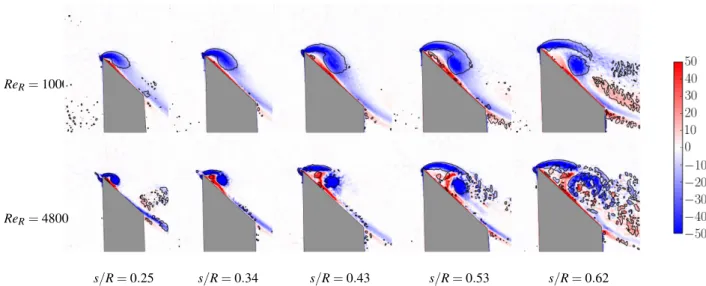
over the wing rotating at two different Reynolds numbers, as can be seen in figure 3. The normalised vorticity contours (ω∗) at different spanwise locations (s/R) indicate that the LEV is smaller near the wing root and grows in size towards the wing tip. The vortex is identified using the Q criterion. The value of Qis the second invariant of the velocity gradient tensor ([9]). It represents the magnitude of the rotation rate relative to the strain rate. Positive values, Q > 1, are chosen to represent the vortex as they identify the area where the magnitude of the rotation rate dominates the strain rate.
At a certain spanwise location, the LEV splits into two co-rotating vortices, known as the dual LEVs. The location of the LEV split depends on the Reynolds number. Figure 3 shows that the LEV splits at a location in the range (0.53 < s/R < 0.62) at ReR= 1000, whereas it splits in the range (0.25 < s/R < 0.34)
at ReR= 4800. The scanning PIV can track the location with
an accuracy of 0.03. The experiments were conducted over a wider range of Reynolds number than shown in figure 3 and the split location was observed to continue to change with ReR. To
highlight this, the split position was plotted as a function of ReR
and this is shown in figure 4. The trend obtained from experi-ments is similar to that obtained from numerical simulations of the same wing shape by [8]. However, the actual values in the experiments differ from the values in the numerical simulations. It could be hypothesised that this difference is due to the pres-ence of the central holder in the experiments, which was absent in the numerical model.
The diameter of the cylindrical central holder in the original experiments was 20 mm. This caused the wing to offset by bo= 10 mm from the axis of rotation. To study the effect of the
central body size, we systematically varied the holder diameter from 15 mm to 35 mm and observed the LEV structure over a range of Reynolds numbers. The results are described in the subsequent section.
Effect of central body size on the LEV split
ReR= 1000
ReR= 4800
s/R = 0.25 s/R = 0.34 s/R = 0.43 s/R = 0.53 s/R = 0.62
Figure 3: Instantaneous normalised vorticity fields (ω∗= ωzR/Ug) are shown for the wing rotating at ReR= 1000 (top) and ReR= 4800
(bottom), at different normalised spanwise locations (s/R). Blue represents counter-clockwise voticity and red clockwise vorticity. The grey region represents the shadow behind the wing. Contours of normalised vorticity lie in the range (−50 < ω∗< 50). The solid black lines are the contours of Q = 1.
0 2000 4000 6000 8000 10000
Re
R 0.2 0.3 0.4 0.5 0.6 0.7 0.8s/
R
Computations (without central body)[8] Experiments (with central body)
Figure 4: The normalised spanwise location (s/R) for the LEV split is shown as a function ReR. The curve obtained from
ex-periments does not match with that from numerical simulations by [8], presumably due to the presence of the central body in the experiments.
the steps of 5 mm. This effectively varied the offset distance in the range (7.5 < bo< 17.5). The investigated range of Reynolds
number was 600 < ReR< 1500. The split locations obtained in
all these cases are plotted in figure 5(a). The figure shows that the split location varies with the holder size. It moves towards the tip when the size is increased from bo= 7.5 mm to bo= 17.5
mm. However, it then moves inward with a further increase in the size.
If we normalise the split location with the wing span b instead of R, the curves move closer to each other, as shown in figure 5(b). In this figure, all the curves, except that corresponding to bo=
12.5 mm, lie close to a common line, within the error limits of the measurements. This indicates that when the Rossby number is changed by changing the wing offset, there is a minimal effect on the LEV structure within the investigated range of holder sizes and Reynolds numbers.
400 600 800 1000 1200 1400 1600 ReR 0.40 0.45 0.50 0.55 0.60 0.65 0.70 0.75 0.80 s/ b bo=7.5mm bo=10.0mm bo=12.5mm bo=15.0mm bo=17.5mm 400 600 800 1000 1200 1400 1600 ReR 0.40 0.45 0.50 0.55 0.60 0.65 0.70 0.75 0.80 s/ R bo=7.5mm bo=10.0mm bo=12.5mm bo=15.0mm bo=17.5mm (b) (a)
Figure 5: The variation of the LEV split location with ReR is
shown for different holder sizes (identified by bo). The split
location is normalised with total span (s/R) in (a) and with wing span (s/b) in (b). The curves move closer together with the scaling s/b.
The results appear counter intuitive when we compare them to the results given in [19]. If we keep increasing the offset dis-tance to larger values, the rotational motion of wing will tend to approach translational motion. It has been observed in the past, for example by [5] and [12], that the flow structures in rotational and translational motions are significantly different. Hence, there must be a limiting value of bo, where a
differ-ence in the flow structure appears. Moreover, the cylindrical holder in experiments also rotates with the wing, generating a secondary flow near the root of the wing. Since the spiral struc-ture of the LEV also comprises a spanwise flow, it can be dis-turbed by the secondary flow at the root. The investigated range of bois insufficient to observe the change in the LEV structure
due to the secondary flow. Thus, further experiments are under-way to investigate a wider range of boand ReR.
Conclusions
The effect of different geometrical and kinematic parameters on the flow structure over a rotating Drosophila wing has been studied in the past. The numerical and experimental results have shown some differences in the observed flow structures. In the present work, we systematically studied the effect of a geo-metrical addition, the central body, which is present in most of the experimental studies. The most important parameters to the problem were the central-body radius (bo) and the span-based
Reynolds number (ReR).
Scanning Particle Image Velocimetry (Scanning PIV) measure-ments of the flow around the rotating wing were performed at different Reynolds numbers. The leading-edge vortex (LEV) structure was obtained from the vorticity field. To characterise the LEV variations, we examined the position where the LEV splits, normalised by the total span. An initial comparison be-tween the present experimental data and the numerical data of [8] showed the difference occurring due to the central body. Varying the central body radius resulted in differences in the LEV split locations. However, these differences were min-imised when the split locations were normalised with the wing span b, instead of the total span R. An unchanged split loca-tion for a given Reynolds number indicates that the overall flow structure is unchanged. Hence, it was concluded that the inves-tigated holder sizes do not significantly affect the LEV struc-ture. This result seems counter-intuitive when one considers previous studies on the effect of Rossby number, although the total Rossby number variation here is not huge. Experiments are currently under way to investigate a wider range of central body sizes and Reynolds numbers.
References
[1] Ansari, S. A., Knowles, K. and Zbikowski, R, Insectlike flapping wings in the hover Part II: Effect of wing geome-try, Journal of Aircraft, 45 (6), 2008, 1976–1990. [2] Birch, J. M. and Dickinson, M. H., Spanwise flow and
the attachment of the leading-edge vortex on insect wings, Nature412 (August), 2001, 729–733.
[3] Carr, Z. R., DeVoria, A. C. and Ringuette, M. J., Aspect-ratio effects on rotating wings: circulation and forces, Journal of Fluid Mechanics767, 2015, 497–525. [4] Dickinson, M. H., Lehmann, F.-O. and Sane, S. P.,Wing
Rotation and the Aerodynamic Basis of Insect Flight, Sci-ence, 284, 1999, 1954–1960.
[5] Ellington, C. P., The aerodynamics of hovering insect flight. I. The quasi-steady analysis, Philosophical
Trans-actions of the Royal Society B: Biological Sciences, 305 (1122), 1984, 1–15.
[6] Ellington, C. P., van den Berg, C., Willmott, A. P. and Thomas, A. L. R., Leading-edge vortices in insect flight, Letters to Nature, 384 (6610), 1996, 626–630.
[7] Fu, J., Hefler, C., Qiu, H. and Shyy, W., Effects of aspect ratio on flapping wing aerodynamics in animal flight, Acta Mechanica Sinicapp., 2014, 1–16.
[8] Harbig, R. R., Sheridan, J. and Thompson, M. C., Reynolds number and aspect ratio effects on the leading-edge vortex for rotating insect wing planforms, Journal of Fluid Mechanics, 717, 2013, 166–192.
[9] Hunt, J. C. R., Wray, A. A. and Moin, P., Eddies, streams, and convergence zones in turbulent flows, Center for Tur-bulence Research, Tech. Rep.CTR-S88, 1988, 193–208. [10] Lee, K.-B., Kim, J.-H., Park, J. S. and Kim, C., Unsteady
aerodynamic effects of wing-body interactions in three-dimensional insects’ flapping flight, 50th AIAA Aerospace Sciences Meeting including the New Horizons Forum and Aerospace Exposition (January), 2012, 1–11.
[11] Lentink, D. and Dickinson, M. H., Biofluiddynamic scal-ing of flappscal-ing, spinnscal-ing and translatscal-ing fins and wscal-ings, The Journal of Experimental Biology, 212 (Pt 16), 2009, 2691–704.
[12] Lentink, D. and Dickinson, M. H., Rotational acceler-ations stabilize leading edge vortices on revolving fly wings, The Journal of Experimental Biology, 212, 2009, 2705–2719.
[13] Liu, G., Dong, H. and Li, C, Vortex dynamics and new lift enhancement mechanism of wingbody interaction in insect forward flight, Journal of Fluid Mechanics, 795, 2016, 634–651.
[14] Lu, Y., Shen, G. X. and Lai, G. J., Dual leading-edge vor-tices on flapping wings, The Journal of Experimental Bi-ology, 209, 2006, 5005–5016.
[15] Ozen, C. A. and Rockwell, D., Flow structure on a rotating plate, Experiments in Fluids, 52 (1), 2011, 207–223. [16] Vogel, S., Flight in Drosophila I. Flight performance of
tethered flies, The Journal of Experimental Biology, 44, 1966, 567–578.
[17] Weis-Fogh, T., Biology and physics of locust flight. II. Flight performance of the desert locust (Schistocerca gre-garia), Philosophical Transactions of the Royal Society B: Biological Sciences, 239 (667), 1956, 459–510.
[18] Wojcik, C. J. and Buchholz, J. H. J., Parameter variation and the leading-edge vortex of a rotating flat plate, AIAA Journal, 52 (2), 2014, 348–357.
[19] Wolfinger, M. and Rockwell, D., Flow structure on a ro-tating wing: effect of radius of gyration, Journal of Fluid Mechanics, 755, 2014, 83–110.