HAL Id: hal-01007029
https://hal.archives-ouvertes.fr/hal-01007029
Submitted on 8 Feb 2017
HAL is a multi-disciplinary open access
archive for the deposit and dissemination of
sci-entific research documents, whether they are
pub-lished or not. The documents may come from
teaching and research institutions in France or
abroad, or from public or private research centers.
L’archive ouverte pluridisciplinaire HAL, est
destinée au dépôt et à la diffusion de documents
scientifiques de niveau recherche, publiés ou non,
émanant des établissements d’enseignement et de
recherche français ou étrangers, des laboratoires
publics ou privés.
Metallic energy-absorbing inserts for Formula One tyre
barriers
Pierrick Guégan, Daniel Lebreton, Franck Pasco, Ramzi Othman, Steven Le
Corre, Arnaud Poitou
To cite this version:
Pierrick Guégan, Daniel Lebreton, Franck Pasco, Ramzi Othman, Steven Le Corre, et al.. Metallic
energy-absorbing inserts for Formula One tyre barriers. Proceedings of the Institution of Mechanical
Engineers, Part D: Journal of Automobile Engineering, SAGE Publications, 2008, 222 (5), pp.699-704.
�10.1243/09544070JAUTO683�. �hal-01007029�
Metallic energy-absorbing inserts for Formula One tyre
barriers
P Guegan*, D Lebreton, F Pasco, R Othman, S Le Corre, and A Poitou
GeM – Research Institute in Civil and Mechanical Engineering, Ecole Centrale Nantes, Nantes, France
Abstract: Most Formula One circuits use tyre barriers for crash protection. Generally, they are composed of bolted tyres, fitted by a conveyor belt to the face of the barriers. The barriers are placed against a rigid wall or a metallic safety barrier. When the protection area is too small, the rigidity of the tyre barrier is improved by polyethylene tubular inserts inside the tyres. The static and dynamic tests realized at the Ecole Centrale de Nantes present the energy boundary condition for the thermoplastic insert used at present. Thus, contrary to what is usually thought, the following studies show that a metallic insert solution is better from an energy dissipation point of view.
Keywords: Formula One, crash, tyre barriers, race car circuit
1 INTRODUCTION
It seems that in the literature there is little on the subject of tyre barriers. However, Wright and Mellor [1–3] studied, in laboratory, many integral tyre barrier configurations by crashing a trolley with initial velocities of 60 and 80 km/h. They showed the improved energy contribution of a thermoplastic tubular insert compared with when tyres were used alone; therefore the barrier rigidity is better with inserts. Thus, the force applied during the crash is more important, but the trolley stopped while acquiring an allowable deceleration. Moreover, the inserts improve the integrity of the barrier, as the tyres are held in position. However, the insert used generates a larger trolley rebound, sometimes equal to an energy ratio of 20 per cent of the initial energy. During a race, this could cause a race car to return to a dangerous position on the race way.
Thus, the aim of this study concerns the improve-ment in the energy absorption properties of the tyre barriers by optimization of its inserts. Before study-ing a new insert, which is able to produce a lower
rebound energy, the actual insert behaviour must be determinate by static and dynamic tests.
2 BEHAVIOUR OF THE PRESENT INSERTS UNDER STATIC LOADING
The insert that is now in operation matches the Fe´deration Internationale de l’Automobile (FIA) Standard 8861-2000 [2]. This document includes the insert specifications and the static test condi-tions for validation by the race car circuit manager. The recognized solution is a tube made of thermo-plastic-type polyethylene (PE) with specific dimen-sions adapted to the internal tyre column. Initially, this product was validated by an FIA crash test [3].
Thus, a tube with the following properties has been selected for experimental investigation: material, PE-HD 100; external diameter D05315 mm; thickness
e 5 12.1 mm; length L051 m (cut, 6 m original).
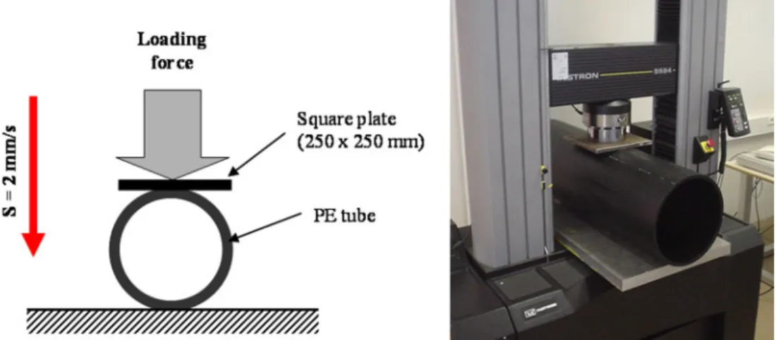
For the static loading, the following FIA standard parameters were used: a loading rate S of 2 mm/s and a radial force in the middle of the tube applied by a rigid square plate indenter of 250 mm6250 mm2 (Fig. 1(a)). To be accurate to specifications, the PE tube must supply a minimum energy of 4 kJ and a maximum radial force of 35 kN, for a radial strain of 0.8 (ratio of the radial displacement DD to the external diameter D0).
*Corresponding author: GeM Research Institute in Civil and, Mechanical Engineering, UMR 6183 CNRS, Ecole Centrale Nantes, 1, rue de la Noe¨, BP 92101, Nantes Cedex 3, 44321, France. email: pierrick.guegan@ec nantes.fr
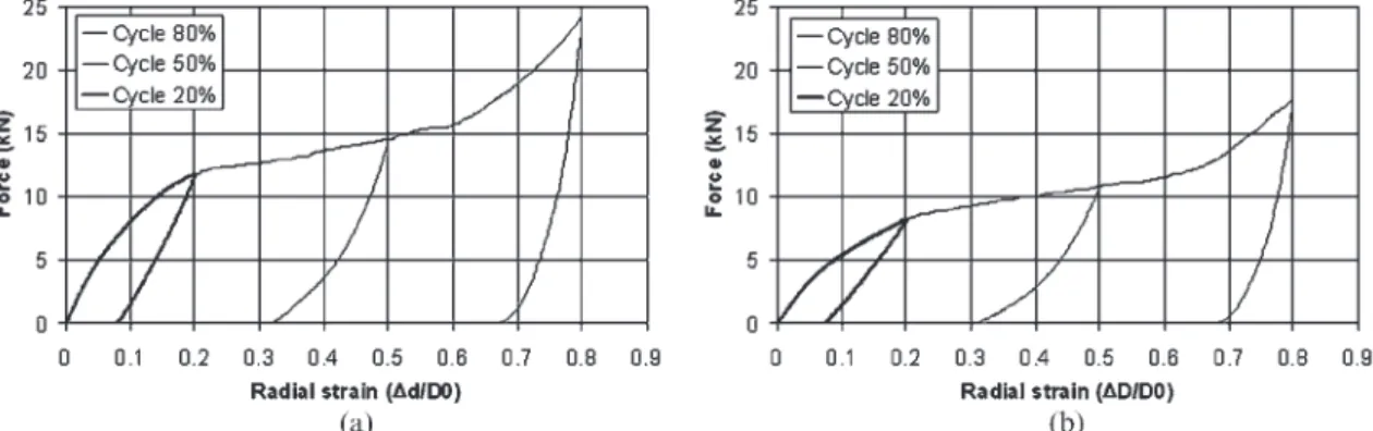
An Instron 5584 static machine was used for these tests on three PE tube specimens (Fig. 1(b)). Each specimen was tested at a different radial strain level of 0.2, 0.5, or 0.8. The operation consists in loading the specimen from 0 to the required radial strain and then unloading to 0 at the same speed. Figure 2(a) shows the evolution of the radial force with the radial strain. First, the accuracy of the selected thermoplastic tube was verified; for a radial strain of 0.8, the maximum force is 33.9 kN (lower than 35 kN) and the supplied energy is 4948 J (greater than 4 kJ). Then, this procedure gives information on the supplied energy Esand the dissipated energy Ed, which is the effective
absorption parameter of the tube insert.
The ratio of the dissipated energy Ed to the
supplied energy Esshows the ability of the insert to
dissipate energy for different crash levels. For the three tested specimens, the ratios are as follows: for a radial strain of 0.2, Ed/Es548 per cent; for a radial
strain of 0.5, Ed/Es565 per cent; for a radial strain of
0.8, Ed/Es580 per cent. The energy ratio is better for
a radial strain of 0.8 because plastic alteration appears at a radial strain of 0.5 (see Fig. 2(a)). The combination of the material behaviour, the tube geometry, and the square indenter causes an amplification of local plastic deformation above this radial strain. Thus, the energy dissipation of the PE tube insert is better for a high radial strain above 0.5. Below this strain level, the PE tube insert has almost elastic characteristics, and so it does not fulfil the criterion for being a suitable absorber. Indeed, a significant part of the absorbed energy is released after the test.
3 BEHAVIOUR OF THE PRESENT INSERTS UNDER DYNAMIC LOADING
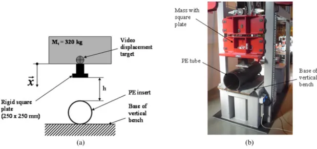
The static investigations were completed by two dynamic tests on similar tubes, realized on the vertical bench at the Ecole Centrale de Nantes (Fig. 3). The experimental conditions are the same
Fig. 2 Results of the three static tests showing (a) the force as a function of the radial strain and (b) the energy as a function of radial strain: test 1, tube specimen 05-110; test 2, tube specimen 05-111; test 3, tube specimen 05-116
as for the static tests, except for the impact speed. The potential energy is produced by a mass Mtof 320 kg,
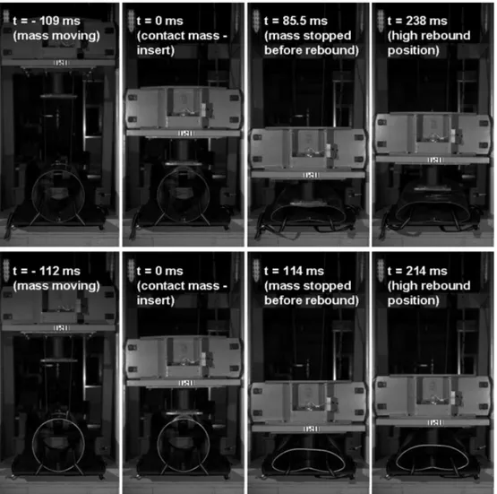
dropped at an initial height h. A high-speed video camera records the test at a frequency of 1000 frames/ s (Fig. 4). Post-treatment of the pictures gives an expression for the mass height during the test (position X1, X2, and X3), and also an expression for
its rebound. For the two dynamic tests, the energy dissipation ratios are explained in Fig. 5 and Table 1. As for the static test, the energy dissipation of the PE tube insert is better for a high strain, greater than 0.5.
In conclusion, the PE insert has an almost elastic behaviour for deformations below 0.5. This explains the increase in the rebound length noticed during experimentation on a barrier including these inserts [1].
4 METALLIC SOLUTIONS
In fact, a problem of the PE tube insert is the high elasticity of the PE material. This is acceptable with Fig. 3 (a) Dynamic test parameters; (b) PE tube on the vertical bench
Fig. 4 Video sequence of dynamic test on a vertical bench (test parameters: tube specimen 05-114; falling height h 1580 mm; contact velocity, 5.6 m/s)
regard to the recovery of the barrier after a crash, but not suitable for optimum energy dissipation. The material has to be changed to improve the energy dissipation of the insert. The creation of a new insert with the same geometry implies using a material that assures some structural integrity during the crash (and therefore without rupture), has a rigidity when used with the weighted force, and, in particular, possesses a minimum elastic return during unload-ing. That is why metallic materials were chosen as they have a better elastoplastic behaviour. For this study, two metallic materials were selected: stainless steel type 304 and aluminium alloy 5754-H111. These materials are stainless (no corrosive problems in use) and their strain failure levels are compatible with crash applications because they withstand a large plastic strain before rupture (greater than 20 per cent). Four prototypes have been made with the following parameters [4]: external diameter
D05321 mm, plate rolled and tungsten–inert-gas
welded; thickness e 5 2.5 mm for stainless steel 304 and e 5 3 mm for aluminium alloy 5754-H111; length L051 m. The thicknesses were initially estimated by
an analytical approach and finite element calcula-tions with the explicit software ABAQUS, with the static conditions defined by the FIA as references.
5 BEHAVIOUR OF THE METALLIC INSERTS UNDER STATIC LOADING
The experimental specifications are the same as for the tests on the PE inserts. A metallic tube is used for the operation, which is divided into three steps, according to three consecutive cycles of loading and unloading at the same speed, for radial deformation levels of 20 per cent, 50 per cent, and 80 per cent. Figure 6 shows the force in terms of the radial strain Fig. 5 Definition of the energy dissipation ratio Ed/Es
Table 1 Parameters and results of the dynamic tests on the PE inserts
PE insert specimen number h (mm) Radial strain DD/D0 X1(mm) X2(mm) X3(mm) Ed/Es(%) 05 114 1580 0.64 0 1781 1271 71 05 115 805 0.43 0 940 532 57
Fig. 6 Force as a function of the radial strain: (a) stainless steel insert specimen 06-050; (b) aluminium alloy insert specimen 06-052
for the two prototypes tested in static loading. First, the plastic alteration observed on the PE curves at a radial strain of 0.5 (see Fig. 2) is not visible in these new results, because the material plastic strain is clearly initiated since the beginning of the test.
For the two static tests on these first prototypes, the global energies used are under the minimum
specification for the PE tube (3464 J for the stainless steel insert and 2507 J for the aluminium alloy insert). This difference is probably due to a variation in the metallurgical state between the materials limit design and the real behaviour of the tested tubes. An increase in the insert thickness would be enough to obtain a final energy equal to that of the PE tube if needed. However, these static tests show that the energy dissipation Ed/Esratio for the three
consecu-tive cycles gives better results with the metallic inserts than with the PE tube (Table 2): 85 per cent and 81 per cent for the tested metallic tubes versus 65 per cent for the PE insert at a radial strain of 0.5; 91 per cent and 92 per cent versus 80 per cent at a radial strain of 0.8. The PE insert tested at a radial strain level of 0.2 has an energy dissipation ratio of 4–9 per cent below those of the metallic materials to date.
Table 2 Results of static tests on PE, stainless steel, and aluminium alloy inserts
Radial strain DD/D0 Ed/Es(%) Stainless steel insert specimen 06 050 Aluminium alloy insert specimen 06 052 PE insert specimen 05 110, 05 111, and 05 116* 0.2 57 52 48 0.5 85 81 65 0.8 91 92 80
*The values for PE inserts are given for comparison.
Fig. 7 Video sequences of dynamic tests on a metallic tubular insert on a vertical bench (test parameters for a high rebound: stainless steel insert specimen 06-051; falling height h 1276 mm; contact velocity, 5.0 m/s) (test parameters for a low rebound: aluminium alloy insert specimen 06-053; falling height h 800 mm; contact velocity, 4.0 m/s)
6 BEHAVIOUR OF THE METALLIC INSERT BEHAVIOURS UNDER DYNAMIC LOADING The dynamic tests were realized with the same specifications as for the PE inserts. In the quasi-static tests at a radial strain of 0.8, the metallic inserts dissipate almost completely the supplied energy: 94 per cent and 96 per cent (see the video sequences in Fig. 7 and the results in Table 3). In contrast, the dynamic test carried out on PE tube specimen 05-114 yielded an energy dissipation ratio of 71 per cent for a radial strain of 0.64.
7 CONCLUSION
Although the crash energy of the prototypes designed for this first study is slightly lower than the FIA energy specifications of the PE tube, the energy dissipating power of a metallic insert under quasi-static and dynamic loading is definitively higher than that of the PE insert used now. In quasi-static conditions, the gain is very interesting at a medium crash level (20 per cent better dissipation at a radial strain of 0.5) and remains significant for a larger crash (increase of 10 per cent at a radial strain of 0.8). It is also positive for a very weak radial strain (6 per cent average of the additional contribution at a radial strain of 0.2). In dynamic conditions, the energy dissipation is almost full scale, with a mean for the two metallic inserts of 95 per cent at a radial strain of 0.89.
Now, the real contribution of this improvement to the general behaviour of the tyre barrier in crash test must be determined. The next steps of this study could be to adjust, if necessary, the metallic insert behaviour, by increasing its thickness, to validate the solution by new quasi-static and dynamic tests, and to realize a crash test on a tyre barrier fitted out with these new inserts, under conditions in conformity with the FIA specifications [3].
ACKNOWLEDGEMENT
Special thanks are due to Mr Franck Corcelle of the FIA for his valuable help.
REFERENCES
1 Wright, P. G. and Mellor, A. Barrier testing. SAE technical paper 983061, 1998.
2 FIA Standard 8861-2000. FIA energy absorbing inserts for Formula One tyre barriers standard, Fe´de´ration Internationale de l’Automobile, Paris, 26 January 2000, available from www.fia.com/sport/ Regulations/standregs.html.
3 FIA safety barriers standard, Fe´de´ration Inter-nationale de l’Automobile, Paris, 26 January 2000, available from www.fia.com/sport/Regulations/ standregs.html.
4 Gue´gan, P., Lebreton, D., Pasco, F., Othman, R., and Poitou, A. Structure amortisseur de chocs, en particulier pour les circuits de compe´titions automobiles. Fr. pat. 07/00547, 26 January 2007.
APPENDIX Notation
D0 external diameter of the insert
e thickness of the tubular insert Ed dissipated energy
Es supplied energy
h falling height on the vertical bench L0 length of the insert
Mt falling mass of the vertical
bench 5 320 kg PE polyethylene
PE-HD high-density polyethylene thermo-plastic material
S loading rate
t time reference in dynamic loading X1 height of the high position before
rebound
X2 height of the low position before
rebound
X3 height of the high position after
rebound
DD radial displacement
DXr indenter displacement during
rebound
DXs indenter displacement during falling
Table 3 Results of dynamic tests on stainless steel and aluminium alloy inserts
Insert h (mm) Radial strain DD/D0 X1(mm) X2(mm) X3(mm) Ed/Es(%)
Stainless steel specimen 06 051 1276 0.84 0 1547 1449 94