Designing the Malqaf for summer cooling in low-rise
housing, an experimental study
Shady Attia
Université Catholique de Louvain, Architecture et Climat, [email protected]
ABSTRACT: The malqaf or windcatcher has been around in Egypt as early as the pre-dynastic period, where a vent of some nature that faces north to catch the cool prevailing winds. This traditional Arabic element has been used successfully in low-rise housing for centuries. The malqaf has been used as a viable solution to ensure natural ventilation by allowing cooler air movement, allow sufficient lighting, avoid offensive glare and reduce the sand and dust in prevalent winds. However, for the last 50 years, Egyptian practice has failed in combining traditional architectural devices into new techniques that could lead to much more sustainable and energy aware buildings. In Egypt, more than half of the urban peak load of energy consumption in the mean time is used to satisfy air conditioning demands alone. Consequently, building cooling using air-conditioners became the single largest consumer of electricity and it accounts for nearly 60% of nation’s peak power demand. Therefore, the objective of the research is to develop a viable passive alternative to active cooling by exploring the potentials and design parameters of windcatchers as solution for passive cooling and natural ventilation during the summer season for low-rise housing. Experimental wind tunnel and smoke visualisation testing were conducted to compare the air flow in a scale model room with and without windcatcher on top of the roof with different orientations. The final result shows that the performance of the windcatcher depends greatly on the position, orientation and size of the inlet and outlet opening in relation to the wall ratio. The study developed a comparative matrix for examined parameters to support architects with the basic principles for windcatchers design. Keywords: malqaf, windcatcher, passive cooling, Egypt
1. INTRODUCTION
1.1 Natural Ventilation in traditional houses
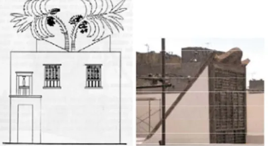
Natural ventilation and passive cooling have been traditionally two important features in ancient Egyptian Architecture, the most outstanding example of which are windcatchers as shown in figure 1. The idea of the malqaf dates back to very early historical times. It was used by the Egyptians in the houses of Tal Al-Amarna and is represented in wall paintings of the tombs of Thebes. One example, shown in figure 1a, is the Pharonic house of Neb-Amun depicted on his tomb, which dates from the nineteenth Dynasty (1300 B.C.). It has two openings, one facing windward and the other leeward, to evacuate the air by suction [1].
Fig. 1.a, Malqaf of the Pharonic house of Neb-Amun, Nineteenth Dynasty (1300 B.C.), fig 1.b. Windcatcher: Sennari House, Cairo (1798)
In most housing examples, the malqaf was placed directly over a roof opening and without a shaft to channel the airflow into the room. Several examples are found in nineteenth-century Turkish-style houses in Cairo, illustrated in fig. 1.b.
1.2 Egyptian Practice
However, for the last 50 years, Egyptian practice has failed in combining traditional architectural devices into new techniques that could lead to much more sustainable and energy aware buildings. The malqaf is one of those vernacular archetypal devices that fall outside existing experience. Today in Egypt, more than half of the urban peak load of energy consumption in the mean time is used to satisfy air conditioning demands alone. Consequently, building cooling using air-conditioners became the single largest consumer of electricity and it accounts for nearly 60% of nation’s peak power demand. Therefore, the new Egyptian Energy Code for residential buildings implies a minimum natural ventilation rate of 3 L/s-person for living and sleeping areas and 14 L/s-person for kitchens and toilets [2]. However, this relatively new code is not enforced until now. On the other hand, we can read from figure 2 that the average wind speed in Cairo is approximately 4 m/s, while the prevailing wind direction is North, and to a limited extent South as indicated by the wind
rose diagram. According to the Egyptian Organisation of Meteorology (EOM), there is a strong seasonal difference with winds in summer blowing almost exclusively from the north and only two months in winter the wind direction is reversed and blows almost exclusively from the south. This means that wind can be used efficiently for natural ventilation at times when outside temperatures have not reached unacceptable levels.
Fig. 2.a, Average annual wind speed and direction in percentage (Egyptian Organisation of Meteorology) Therefore, the objective of the research is to develop a viable passive alternative to active cooling by exploring the potentials and design parameters of windcatchers as solution for passive cooling and natural ventilation during the summer season for low-rise housing. In the present study, the results of the first stage in a series of studies are presented and discussed. The study analyzed flow patterns of windcatchers in low-rise buildings through smoke visualizations in wind tunnel. Relatively, simple cases were modelled with low air speed. The parameters involved in this study were position, orientation, entry cross section, shaft cross section, shaft height, and outlet opening in relation to the wall ratio.
1.3 Function of a Malqaf
The malqaf is a shaft rising high above the building with uni-directional opening facing the prevailing wind. It traps the wind from high above the building where it is cooler and stronger, and channels it down into the interior of the building. The malqaf thus dispenses with the need for ordinary windows to ensure ventilation and air-movement in addition to enhancing indoor environmental quality. The malqaf is also useful when filters are integrated within the shaft; in reducing the sand and dust so prevalent winds of hot arid regions [1].
In fact, the malqaf is an important bioclimatic archetype in dense cities in hot dry climates, where thermal comfort depends mostly on air movement, evaporative cooling and thermal mass [3]. Since masses of buildings reduce the wind velocity at street level and screen each other from the wind, the ordinary window is inadequate for ventilation. This situation can be
corrected by using the malqaf. In this respect it is not only the inflow of unpolluted fresh air into the area that plays an important role, but equally the cooling effect on the buildings during the night. The bottom line is that windcatchers serve mainly for the following functions [4]:
1- Ventilation across the space 2- Provide convective cooling 3- Cool the thermal mass of the space
2. METHODOLOGY
This study investigated, both theoretically and experimentally, the interaction between parameters considered to be important in achieving natural ventilation, passive cooling and indoor environmental quality [5]. The research has been carried out in two parts. The first part consisted of an analysis of existing malqaf houses, necessary to identify the main design parameters and traditional design settings. The second part compromised the flow visualisation in wind tunnel for a model that resembles the traditional buildings in Egypt. Each part was started with a literature review on the specific subject.
2.1 Part 1: Analysis of design parameters of the Malqaf
In planning for the malqaf, several geometrical parameters have to be investigated. In order to realize passive cooling through natural ventilation during the summer season for low-rise housing, we must design and position the
malqaf to allow cross ventilation and maximum
air speed within the space [6, 7]. As a result of an extensive analysis of existing traditional buildings in Egypt the following parameters were found and identified [4, 8]:
Position
Among all examined cases, two settings of catchers were found as shown in fig.3. In the first setting (fig 3.a), which was the most common in traditional buildings, the malqaf was located on top of the roof of the ventilated space itself facing the on-coming wind. Next, in the second setting (fig 3.b), the catcher was located on the windward side in combination with courtyard.
Fig. 3.a. Malqaf on top of the space, Fig.3.b.Malqaf in the back in combination with a courtyard
The courtyard was mainly used as a cool
to the surrounding spaces. However, this study is limited to the first setting.
Orientation
The typical orientation of the malqaf was found facing the prevailing winds. Given that the catcher is uni-directional, the entry is sensitive to capture prevailing wind. Therefore, it is very important to look at the probability of wind distribution speed and direction on site for maximum natural circulation. In most analysed cases we find that the malqaf was oriented towards the north-west from 0o to 7o
Inlet cross-section and shape
Traditionally, we find that the shape of the top end of the malqaf was inclined with a slope of 30o to 45o. Also, we find that the area of the entry cross-section identical to the shaft cross-section area. In fact, the inlet determines the amount of wind trapped from high above the building and channels it down into the interior of the building.
Shaft cross-section and height
In most traditional buildings we find that the shaft was built-in the ventilated space. Generally, the shaft was square or rectangular and its relative height was 1-1.2 H, where H is the height of the space. Moreover, it was found that the shaft cross-sectional area is around 3% of the ventilated space floor area. The shaft height ranged from 0m to 10m, but the most common height in Cairene buildings was 6m and generally the malqaf projected at least one storey above roof height. However, for this study the examined prototype shaft height was zero and the shaft cross section area equalled the entry cross-section area.
Outlet opening
We find that the size of the outlet opening had an important effect on the air flow acceleration. The ratio of outlet opening to wall was similar in most lee side walls of historical buildings with
malqaf. The ratio varied from 0.4 to 0.6.
However, in many cases additional wind escapes such as shukhshikha (stack-driven roof opening) and mashrabiyas (screened windows) made it difficult to precisely calculate this ratio.
Evaporative systems
In some of the analysed buildings, the malqaf was directing the airflow over water elements in order to achieve evaporative cooling. However, evaporative cooling is excluded from the study.
2.2 Part 2: Flow visualisation and test facility
Flow visualizations are the best tool for illustrating air flow around buildings and they are highly instructive for any design. Flow visualisations are important for architects because they make it possible to analyse and propose suitable solutions for windcatchers design [9]. The visualization of the airflow clarify the areas of streaks, stagnation, and separated flow and reattachment zones inside the
building [10]. Several practical methods of flow visualization are available [11]. Such importance not only in giving clear qualitative images of flow phenomena, but also, in some cases, in yielding quantitative information [12-14]. In this study, video image were recorded for the different model settings.
Wind tunnel and smoke visualisation
The flow visualisation tests were conducted in the wind tunnel, built in the Thermodynamics and Turbo Machines Unit of the School of Engineering at the Catholic University of Louvain (UCL). As shown in fig.4, the wind tunnel is an open circuit type with a test section 1.2x1m and a 30m long working section. The smoke was exhausted from the smoke chambers using polyvinyl alcohol. Smoke flow patterns were recorded on the video tape using a black background. Smoke flow patterns of fifteen different settings of the malqaf model were visualized and recorded.
Fig. 4, Wind tunnel facility, UCL.
Test model
Airflow visualizations have been made for a single floor house prototype that resembles the traditional buildings in Egypt. The building prototype is of general form and is not depending on any kind of mechanical cooling. Simple test model, representing low-rise residential prototype, was constructed from Plexiglas sheet 5-mm thickness and has a dimension of 60cm x 25cm x 20cm height as shown in fig.5. It was assumed to be made to a 1:20 scale in the wind tunnel. The model had 10 fixed points to place the anemometer and measure the air velocity. The model was tested in the wind tunnel as shown in figure 4&5.
Fig.5, Plexiglas model was constructed to allow multiple settings, scale 1:20.
All the flow visualisations were carried out with the same wind speed 2m/s using air at
atmospheric pressure. and various wind direction (a = 0°, 10°, 20°, 30°, and 45°). This set of tests was intended to investigate the effect of combinations of openings on flow configuration inside the model (building space), hence on air flow patterns therein.
3. RESULTS
Figure 6,7 and 8 summarize air flow visualisation and rates recorded through the different settings of the malqaf space. The experimental results carried out in the smoke tunnel visualised the flow patterns inside the test model. Also we have measured the velocity, not taking in account internal resistances such as filters. The measurements were based on influence of design parameters (2.1) on the prototypical model. The air velocity profile at test section was measured and presented. It is important to mention that the results are not representing the full scale experience. In fact, the main concern here was to observe the relative effect of specific parameters on the resulting natural ventilation performance. At present, setting 1 was without malqaf and therefore will be reported later in the comparative matrix (4).
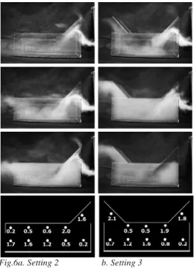
Setting 2
Setting 2 investigated the effect of placing one
malqaf in front in combination with various
outlet openings in the back on the air flow pattern in the model (fig 6a). The best arrangement for getting maximum air flow pattern into the space was achieved when the ratio of outlet opening to wall was 0.6 and when the opening was placed near the floor. The measurements showed that movement of air under the ceiling are slow but are higher in the standard level plane. Setting 2 provided an increase of 200% in the flow rate.
Setting 3
In the case of setting 3, two malqafs were used as shown in figure 5.b, one toward the wind and the other toward the leeward. This case is appropriate, in a space where it is undesirable to place any window in the walls, to permit air movement inside the room. More importantly, the measurements confirmed that this setting was the most effective and significant settings among all other design scenarios. This setting increased the airflow rate and recorded the highest air flow rate. Moreover, this setting has the potential to encourage cross ventilation in the space, during the two months in winter, when wind direction is reversed and blows almost exclusively from the south. Also a turbulent air motion was observed in the zone below the inlet opening. This turbulent curved air movement has also been observed in setting 4. Finally, setting 3 provided an increase of 280% in the flow rate.
Fig.6a. Setting 2 b. Setting 3
Setting 4
In setting 4, two malqafs were placed on the roof both facing the wind. The air flow visualisation shows that the second malqaf on the left became a wind-escape due to the suction caused by the airflow pattern due to the low-pressure zone. The measurements showed that the movement of air under the ceiling are higher than the standard plane. Setting 4 provided an increase of 240% in the flow rate (fig. 7a).
Fig. 7a. Setting 4 b. Setting 5 (m/s)
Setting 5
When the malqaf is placed at the back of the model facing the wind, but the outlet window
covers the full area of the wall, the air flow direction was from right to left. Placing the catcher in the back in combination with various frontal windows showed that the malqaf became a wind-escape. Therefore this setting is not successful especially when placed within a dense urban context (fig.7b).
Setting 6 and 7
The purpose of setting 6 and 7 was to define the optimal orientation of the malqaf. Flow visualisations were carried out for a range of wind direction from 0°, 10°, 20°, 30°, until 45°. Due to the uni-directional nature of the malqaf, it was found that orientation is a very important and sensitive parameter. The performance of the catcher is optimal if the orientation is kept 0° ±10°. After this range, the air escapes from entering the malqaf. However, it is important to mention that the 45° orientation creates a turbulent flow that washes the whole model space creating spiral air circulation (fig. 8).
Fig.8a. Setting 6 b. Setting 7
Summing up the above mentioned results it was found that in general the size of the outlet opening plays a key role in accelerating the air velocity. First of all, the larger and higher elevated the inlet and outlet opening is the higher is the airflow rate. Secondly, it is very important to allow the building occupants to control the inlet and outlet openings during winter and stormy weather when outside air is not welcomed. Thirdly, the malqaf buildings have to be located in sites with environmental and hygienic qualities away from any source of pollution. The ancients located their buildings by hanging pieces of meat in different sites and decided upon the one where the meat lasted longest [15]. Fourthly, in designing the malqaf, they always kept a balance between the opening areas and space floor-area to avoid discomfort caused by high solar radiation (overheating and glare), cold and dusty wind. Finally and above all, convective cooling of thermal mass should be
encouraged by maximizing the total accessible volume of thermal mass materials that has its surface exposed to cool air.
4. COMPARATIVE MATRIX
In order to support the designer with solid design guidelines we have used the measurements to calculate the air change rates in the various model settings, not taking in account internal resistances such as filters. The results of the calculations indicated that by adding the
malqaf(s), one could obtain up to 5.6 air changes
per hour with an opening ratio of 0.6 and the reference velocity of 2m/s (S3). The results confirm that the best arrangement for getting maximum air flow pattern into the space is to make the malqaf inlet and outlet as large as possible. A comparative matrix was created (fig. 9), listing air change rates calculated for the different model settings. In planning for the
malqaf, it was observed that the malqaf position,
orientation, inlet shape, shaft height and outlet opening are some of the main factors in controlling wind environment. It is found that for summer cooling in low-rise housing using the
malqaf has the advantages of higher values of air
change rates and higher air velocities over ordinary flat-roof buildings with windows, which leads directly to keeping spaces more comfortable.
5. CONCLUSIONS
Due to the increasing density of existing and future urban areas in Egypt there is an increasing electric demand caused by mechanical cooling in summer. Therefore, it is essential to take into account the natural ventilation using the malqaf for summer cooling in low-rise housing. Urban planning and development must take into account essential wind patterns and air currents during the summer. It is important during the initial planning stage to achieve natural ventilation of the urban area and a minimisation of urban heat island.
Indeed this study proofed that buildings that includes the malqaf, can significantly alter the direction of the prevailing winds and keep spaces more comfortable. The aerodynamic flows of the
malqaf induced more inflow rate through the
examined building. Also measurements and calculations revealed the effectiveness of two specific settings. Setting 2b proofed that by placing a malqaf on a 1:20 test model one can obtain up to 4 ACH with a outlet wall to opening ratio of 0.6 (reference velocity of 2m/s). Next, setting 3 proofed that one could obtain up to 5.6 air changes per hour with an opening ratio of 0.6 and the reference velocity of 2m/s on a 1:20 scale model. The best arrangement for getting maximum air flow pattern into the space was to make the inlet and outlet as large and high as possible. This can be achieved when placing two
malqafs one toward the wind and the other
toward the leeward. This paper has investigated the potential of integrating the malqaf in residential low-rise housing and proofed that the
malqaf can be utilized to serve the need of
sustainability in contemporary Egyptian practice. However, this study was conducted on a scale of an individual single-space. Therefore, it is important to extend the endeavour to include physical and geometrical parameters, such as convective cooling of thermal mass, building layout and urban fabric. Many existing malqaf buildings succeed only when combined with courtyards. Also the urban context including the arrangement of buildings with the site topography, site environmental and hygienic qualities, landscape features and climatic characteristics, was basic issues that enable natural ventilation in the malqaf house.
6. FUTURE WORK
In the second phase of the research, the authors will continue with visualising and measuring the performance of different building settings
including courtyards. Also CFD simulations will be conducted to analyse and explore the more complex combination of design parameters, in order to predict the human comfort within
malqaf spaces for naturally ventilated and cooled
spaces.
7. ACKNOWLEDGEMENTS
The author expresses his thanks to Prof. Hervé Jeanmart at the Mechanics Department and Michel at the Thermodynamics Lab for their assistance in conducting the experimental work. Also the author extends his gratitude for the valuable advising of Prof. André De Herde and the research team of Architecture et Climat, at the Université Catholique de Louvain.
8. REFERENCES
1.Fathy, H., W. Shearer, and A. Sultan, Natural energy and vernacular architecture: principles and examples with reference to hot arid climates. 1986, Chicago: Published for the United Nations University by the University of Chicago Press. xxiii, 172 p.
2.HBRC, Egyptian code for energy efficiency improvement in buildings, ECP306, (2005), M.o. Housing, Editor. 2005, HBRC Cairo.
3.Givoni, B., Comfort, climate analysis and building design guidelines. Energy and Buildings, 1992. 18: p. 11-23.
4.Al-Wakil, S. and M. Siraj, Climate & the architecture of hot regions [in Arabic]. Third ed. 1989, Cairo: Aalam Al-Kutub.
5.Bahadori, M., An improved design of wind towers for natural ventilation and passive cooling. Solar Energy, 1985. 35(2): p. 119-129.
6.ASHRAE, ASHRAE handbook. Fundamentals. 2005, American Society of Heating, Refrigerating, and Air-Conditioning Engineers: Atlanta, Ga. p. v. 7.Allard, F. and S. Álvarez, Natural ventilation of buildings. A design handbook 2002, London: James & James.
8.Asfour, O. and M. Gadi, Effect of integrating wind catchers with curved roofs on natural ventilation performance in buildings. Architectural Engineering and Design Management, 2006: p. 289–304
9.Yaghoubi, M., Air flow patterns around domed roof buildings. Renewable Energy, 1991. 1(3/4): p. 345-350.
10.Hassan, M., et al., Investigation of effects of window combinations on ventilation characteristics for thermal comfort in buildings. Desalination, 2007. 209: p. 251-260.
11.Pankhurst, R., Wind-Tunnel Techniques. 1968, London.
12.Bienkiewicz, B. and J. Cermak, A flow visualization technique for low-speed wind-tunnel studies. Experiments in Fluids, 1986. 5.
13.Lawson, T., Building Aerodynamics. 2001: Imperial College Press.
14.Cermak, J. and N. Isyumov, Wind Tunnel Studies of buildings and structures. 1998: ASCE. 15.Rabbat, N., The Citadel of Cairo. 1995: BRILL.