Design of the ERIS instrument control software
Andrea Baruffolo *
a, Bernardo Salasnich
a, Alfio Puglisi
b, Paolo Grani
b, Xiaofeng Gao
c, Erich
Wiezorrek
d, Daniela Fantinel
a, Gianluca Di Rico
e, Jens Knudstrup
f, Christophe Moins
f, David Barr
f,
Alexander Buron
d, Mario Kiekebusch
f, Dan Popovich
f, Christian Rau
d, Christian Soenke
f, Chris
Waring
ca
INAF – Osservatorio Astronomico di Padova, vicolo Osservatorio 5, 35122 Padova, Italy;
bINAF –
Osservatorio Astrofisico di Arcetri, Largo Enrico Fermi 5, 50125 Firenze, Italy;
cUK Astronomy
Technology Centre, STFC, Blackford Hill, Edinburgh, EH9 3HJ, UK;
dMax-Planck-Institut für
Extraterrestrische Physik, Giessenbachstrasse 1, 85748 Garching, Germany;
eINAF – Osservatorio
Astronomico d’Abruzzo, Via Mentore Maggini, 64100 Teramo, Italy;
fEuropean Southern
Observatory, Karl-Schwarzschild-Str. 2, 85748 Garching bei München, Germany
ABSTRACT
The Enhanced Resolution Imager and Spectrograph (ERIS) is a next-generation, adaptive optics assisted, near-IR imager and integral field spectrograph (IFS) for the Cassegrain focus of the Very Large Telescope (VLT) Unit Telescope 4. It will make use of the Adaptive Optics Facility (AOF), comprising the Deformable Secondary Mirror (DSM) and the UT4 Laser Guide Star Facility (4LGSF). It is a rather complex instrument, with its state of the art AO system and two science channels. It is also meant to be a "workhorse" instrument and offers many observation modes. ERIS is being built by a Consortium of European Institutes comprising MPE Garching (D), ATC (UK), ETH Zürich (CH), Leiden University (NL) and INAF (I) in collaboration with ESO. The instrument passed Final Design Review in mid-2017 and is now in the MAIT phase. In this paper we describe the design of the ERIS Instrument Software (INS), which is in charge of controlling all instrument functions and implementing observation, calibration and maintenance procedures. The complexity of the instrument is reflected in the architecture of its control software and the number of templates required for operations. After a brief overview of the Instrument, we describe the general architecture of the ERIS control network and software. We then discuss some of the most interesting aspects of ERIS INS, like the wavefront sensors function control, AO secondary loops, IFS quick-look processing and the on-line processing for high-contrast imaging observations. Finally, we provide some information about our development process, including software quality assurance activities.
Keywords: Instrument control software, software development process software quality assurance, adaptive optics, high
contrast imaging, integral field spectroscopy.
1. INTRODUCTION
The Enhanced Resolution Imager and Spectrograph1 (ERIS) is a next-generation, adaptive optics assisted, near-IR
imager and integral field spectrograph (IFS). The instrument will be mounted at the Cassegrain focus of the Very Large Telescope (VLT) Unit Telescope 4 in Paranal, Chile, in early 2020. It will make use of the Adaptive Optics Facility (AOF)2, comprising the Deformable Secondary Mirror (DSM) and the UT4 Laser Guide Star Facility (4LGSF).
It is a rather complex instrument, with its state of the art AO system and two science channels: NIX and SPIFFIER. NIX3
primary function is to provide imaging capabilities from the J to M band. Besides pure imaging, NIX will also offer Sparse Aperture Masking (SAM) imaging, Apodizing Phase Plate (APP) and Focal Plane Coronagraphy (FPC) as well as Long Slit Spectroscopy (LSS). SPIFFIER4 is an upgrade of the existing SPIFFI near-infrared, integral field spectrograph,
part of the SIFONI5 facility. The upgrade consists of new motors, electronics, pre-optics, filters, collimator mirrors, at
least one new diffraction grating and a new detector.
ERIS is meant to be a "workhorse" instrument and therefore offers many AO and observation modes. The AO modes are: “full” correction using both an LGS and an NGS, for higher sky coverage, NGS only, with sufficiently-bright natural reference source, “seeing-enhancer”, using an LGS only for high-order correction, i.e. if no NGS is available, and “seeing-limited”, when no AO correction is performed. Concerning instrument modes, we’ve already mentioned that NIX will offer standard imaging, but also SAM, APP, FPC and LSS. SPIFFIER, while in principle offering just a single mode, Integral Field Spectroscopy, has actually a variety of fixed configuration options for the pixels scale and the spectral settings (wavelength and resolution). Furthermore, ERIS offers field-stabilized and pupil-stabilized de-rotation modes, as well as non-sidereal tracking, when either the natural reference source or the target are Solar-System Objects. The instrument is being built by a Consortium of European Institutes comprising MPE Garching (D), ATC (UK), ETH Zürich (CH), Leiden University (NL) and INAF (I) in collaboration with ESO. ERIS passed Final Design Review in mid-2017 and is now in the MAIT phase.
In this paper we describe the design of the ERIS Instrument Software (INS), which is in charge of controlling all instrument functions and implementing observation, calibration and maintenance procedures. The complexity of the instrument is reflected in the architecture of its control software and the number of templates required for operations. After a brief overview of the Instrument functions, we describe the general architecture of the ERIS control network and software. We then discuss some of the most interesting aspects of ERIS INS, like the wavefront sensors function control, AO secondary loops, IFS quick-look processing and the on-line processing for high-contrast imaging observations. Finally, we provide some information about our development process, including software quality assurance activities.
2. INSTRUMENT FUNCTIONS
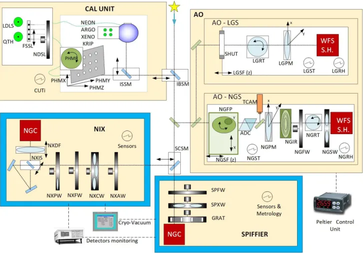
Figure 1 gives a conceptual view of the ERIS functions that must be controlled by the Instrument Software. The ERIS instrument is subdivided in four sub-systems: Calibration Unit6 (CU), Adaptive Optics module7 and two science
channels: NIX and SPIFFIER.
From a control-software point of view, the Calibration Unit consists of a set of standard calibration functions: motors for light path selection (through the movement of mirrors and/or fibers), various types of lamps and neutral density filters. The most complex function in ERIS CU is the positioning of the pinholes mask (PHM-prefixed functions in the Figure), which needs to be moved in three directions and rotated.
In ERIS, the Adaptive Optics module contains two wavefront sensors (WFS): one for the Laser Guide Star (LGS) and one for the Natural Guide Star (NGS). The LGS WFS contains a shutter (SHUT) to protect the detector from over-illumination, a pupil rotator (LGRT) to counter-rotate the pupil when observing in field-stabilized mode (i.e. following the sky), a pupil stabilization mirror, which keeps the pupil aligned with the detector, and the WFS detector which includes a Shack-Hartmann lenslet array. The whole LGS WFS bench is mounted on a linear axis (LGSF) which compensates for the LGS focus. The pupil mirror and focus devices are operated by INS based on input received from the AO Real Time Computer (RTC).
The NGS WFS channel contains a “Field Patrol” device (NGFP), an Atmospheric Dispersion Compensator (ADC), a Technical Camera (TCAM), a pupil mirror (NGPM), a spatial filter (NGIR), a filter wheel (NGFW), a pupil rotator (NGRT), a Shack-Hartmann lenslet array selector (NGSW) and the WFS camera. The Field Patrol device is composed of a linear and a rotary stage and is in charge of picking up the light from the NGS, which can be off-axis, and track it. Tracking is required when the NGS is off-axis and the observation is performed in pupil-stabilized mode. Tracking is also required when either the target or the natural reference source is actually a solar-system object, i.e. it moves non-sidereally. The technical camera is used to support NGS acquisition (the experience at AOF2 shows that this is not
necessary for the LGS). Also in the case of the NGS WFS the whole bench is mounted on a linear axis (NGSF) which compensates for differential focus w.r.t. the science channel in use.
Both WFS channels contain also sensors for temperature (LGST, NGST) and relative humidity (LGRH, NGRH). In NIX, devices to be controlled by INS are, in order from the entrance window to the science detector: aperture, coronagraph, filter and pupil plane optics wheels, an image scale selection mechanism, a focusing mechanism, the science detector and some sensors.
Regarding the number of functions to be controlled, SPIFFIER is the simplest ERIS sub-system, consisting, besides the science detector control electronics, of three motorized functions (filter, optics and grating wheels) and some sensors.
Figure 1: Conceptual view of ERIS Instrument functions.
3. CONTROL NETWORK
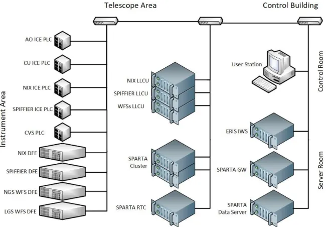
The general architecture of the ERIS control network is illustrated in Figure 2. Control electronics physically closer to the instrument hardware are shown on the left, in the “Instrument Area.” These components include the NIX and SPIFFIER Science Detector Control Electronics (DFE) and the Natural (NGS) and Laser Guide (LGS) Star Wave-Front Sensors (WFS) DFEs. Besides detector electronics, four Programmable Logics Controllers (PLCs) are devoted to instrument functions control and sensor monitoring. According to the new ESO standard for control systems of VLT/VLT Instruments8, these PLCs are based on Beckhoff Embedded PCs and EtherCAT fieldbus. Each PLC is
dedicated to a specific instrument sub-system: Adaptive-Optics WFSs, Calibration Unit, NIX and SPIFFIER. This architecture, with one PLC per sub-system, has been adopted because it allows to integrate and test each sub-system independently, greatly simplifying AIT. The AO PLC also receives precise time (PTP, IEEE1588), required for the control of “tracking axis” (de-rotators, ADC and field patrol), via a dedicated link, not shown in the figure. Finally, all cryogenic and vacuum functions and sensors are controlled by a dedicated Siemens Simatic S7 PLC, which works autonomously and is only monitored by the Instrument Software. All the PLCs, the DFEs and other electronics components which must also reside close to the instrument, are located in cabinets mounted on a co-rotator at the Cassegrain focus of UT4.
All the electronics and computers which must be located within a limited distance from the instrument but don’t need to be close to it, are placed in a dedicated area in the Telescope building. This includes all detectors Linux Local Control Units (LLCUs), part of the New General Controller9, and the SPARTA Real-Time Computer10, composed of a
VME-based hard-RTC and a cluster (soft-RTC).
The Instrument Workstation (IWS), where the coordination and supervisory part of the Instrument Software runs, is located in a Server Room in the VLT Observatory Control Building. In the same place are located the SPARTA Gateway
and the Data Server. The former hosts software which mediates between the IWS and SPARTA RTC; its main purpose is to reduce coupling between the two systems allowing, e.g., software and hardware updates in the IWS without affecting SPARTA (and vice-versa). The SPARTA Data Server is a general facility, not devoted exclusively to any specific instrument, for storing and analyzing large amounts of data collected in real-time using SPARTA “data recording” functionality, which allows to record in real-time a number of loop parameters (intensities, slopes, DM commands, etc).
Figure 2: Conceptual architecture of ERIS control network.
4. INSTRUMENT SOFTWARE ARCHITECTURE
Since ERIS is an instrument for the VLT, the overall partitioning of control software functions must follow the standard architecture for VLT Instrument Software applications.
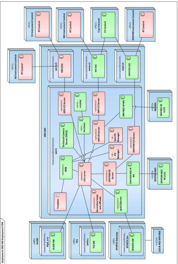
The architecture of the ERIS Instrument Software is illustrated in Figure 3, where components which will be re-used from the VLTSW framework are shown in light-green, while components specifically developed or customized for ERIS are shown in light-red.
For each science channel, three main components are present: an Instrument Control Software (ICS), in charge of controlling all hardware functions except detectors, a Detector Control Software, and an Observation Software (OS), in charge of the coordination of ICS and DCS for the execution of individual exposures. The Detector Control Software is composed of several processes: some running on the IWS, whose main task is to interface with OS and transfer bulk data, and some running in the LLCU, controlling the hardware and interfacing the processes in the IWS. The Instrument Control Software is also composed of several parts: one server process in the same execution environment of the OS, which acts as a front-end, a set of device drivers in a dedicated execution environment in the IWS (DCE or Device Control Environment) and, finally, a part running in the PLC, providing real-time control of functions.
The overall coordination of all internal sub-systems and the interface with external systems is a task of the Super-OS (SOS). SOS interfaces directly with the AO and CU ICS, as well as with the Technical DCS. In this case, an “intermediate” OS is not foreseen, unlike what has been done for NIX and SPIFFIER, because the main task of OS is the
coordination of the execution of science exposures, which only applies to the science channels and not the AO and CU subs-systems.
During normal operations, the instrument is operated by means of templates: scripts which implement all target acquisition, observations, calibrations and maintenance procedures. Templates are grouped in Observation Blocks, which are read and executed by the Broker of Observation Blocks (BOB). SOS receives commands from BOB, processes and forwards them to the appropriate sub-systems, collects science data and instrument status information and forwards them to the Archiver process for the creation and archiviation of data products.
4.1 Interfaces
ERIS INS must manage a number of interfaces: with the hardware functions, detectors, SPARTA, the telescope control system, the Four Laser Guide Stars Facility (4LGSF) and the archive.
The interface with the hardware functions is materialized in the configuration of signals, communication channels, motor parameters, etc., that are stored in a TwinCAT “solution” (the TwinCAT development system is based on Microsoft Visual Studio and adopts the same “solution” file format). The complete solution is archived in SVN directly from the Microsoft Visual Studio environment.
Since the science detectors control system is based on NGC, the corresponding interface is represented by a set of configuration files, archived as a software module, which are used by the NGC software to properly drive the hardware. It is to be noted that the control of AO detectors, also based on NGC, is entirely managed by SPARTA and is not part of INS.
Control of the Technical Camera conforms to the new ESO standard for technical detectors11 which is based on the GigE
Vision protocol. The technical camera software is therefore an application of ESO Technical Detector Control Software (TDCS) toolkit.
The interface with SPARTA is purely software and consists of commands and data. Commands are mediated by a process (spaCCSServer) running in the INS IWS execution environment, which takes care of routing them to the appropriate component in the SPARTA gateway. Data are exchanged through a variety of mechanisms, depending on the purpose: shared memory (e.g. for data to be displayed), files on shared storage (e.g. data recorded by SPARTA or matrices to be loaded in the RTC) or the database (e.g. status information).
ERIS INS interfaces with the telescope for “normal” operations (e.g. slew to target, perform offsets) as well as during observations with AO for offloading defocus, coma and low-order aberrations from the DSM to the Telescope Active Optics.
The artificial source for AO is provided by the Four Laser Guide Stars Facility. As the name implies, 4LGSF is capable to produce four artificial sources, of which only one is used by ERIS. INS interfaces to 4LGSF to select the LGS (any of the four can be used), point it, set focus position and offset, ask for laser propagation, ask for laser tuning/detuning (for calibration), get status information for display and/or storage in the FITS header of the science images.
4.2 Instrument modes and templates
As already anticipated, ERIS is a “workhorse” instrument, which offers many observation modes. This is reflected in the number of templates to be implemented. At the moment, it is expected to develop about twenty acquisition, ten observation, twenty calibration and more than fifty maintenance templates, or about one hundred templates in total. Concerning target acquisition, separate templates are needed for the supported AO modes: “full” AO, where an LGS is used as reference source for the high-order loop and an NGS for tip-tilt and “truth” sensing, NGS AO, where a natural reference source is used both for tip-tilt and high order correction, and the no-AO mode, where no correction is performed. A “seeing-enhancer” mode is also foreseen, where the LGS is not complemented by an NGS, as a special case of the “full” AO mode. In all AO modes where an NGS is foreseen, the natural source can also be a Solar System Object (SSO). In this case, ephemerides are attached to the OB, passed to INS so that the field patrol device can follow the trajectory resulting from the non-sidereal movement between the science target and the reference source.
d e p lo yme n t ER IS IN S D e p lo yme n t FD R ER IS IWS « e xe cu ti o n En vi ro n m e n t» w e ri s « p ro ces s» :S O S ser ve r « p ro ce ss » :B O B « p ro .. . :A rc h iv e r « p ro ce ss » :E R IS IC S Se rv e r « e xe cu ti o n En vi ro n m .. . w e ri cs 1 « e xe cu ti o n En vi ro n m .. . w n xi cs 1 « e xe cu ti o n En vi ro n m .. . w sp ic s1 « p ro ce ss » :N IX IC S Se rv e r « p ro ce ss » :N IX O S Se rv e r :N IX N GC -I R WS « p ro c. .. :v cs o la c « p ro ce ss » :S P IF FI ER O S Se rv e r « p ro ce ss » :S P IF FI ER IC S Se rv e r :S P IF FI ER N G C -I R WS « P LC » C ry o -V ac u u m « P LC » N IX In st ru me n t C o n tr o l R T C o n tr o l C V C o n tr o l « LL C U » N IX N GC N IX N GC -I R LL C U « LL C U » SP IF FI ER N GC SP IF FI ER N GC -IR L LC U « W S» SP A R TA Ga te w ay « LL C U » LGS & N GS WF S N GC « p ro ce ss » sp aC C SS e rv e r « W S» TC S « e xe cu ti o n En vi ro .. . SP A R TA E n v SP A R TA S W « e xe cu ti o n En vi ro .. . w t4 tc s TC S SW « W S» 4 LGS F « e xe cu ti o n En vi ro .. . 4 lg sf _e n v 4 LGS F SW Te m p la te s « P LC » A O In st ru me n t C o n tr o l « P LC » SP IF FI ER In st ru me n t C o n tr o l R T C o n tr o l R T C o n tr o l Te ch n ic al C ame ra Se rv e r (T D C S) « P LC » C U In st ru me n t C o n tr o l R T C o n tr o l « p ro ce ss » Se co n d ar y lo o p s an d o ff lo ad s « p .. . P SI M an ag e r SP IF FI ER D C E N IX D C E ER IS D C E « p .. . Q A C IT S M an ag e r
4.3 Secondary loops and offload manager
In a typical AO-assisted instrument, during normal operations several secondary loops and offloads must be active, at a frequency much lower than the AO loops, to keep the system working nominally.
In ERIS INS a component, labelled “Secondary loops and offloads in Figure 3, is dedicated to this task and is in charge of:
• Offloading of DSM actuators to TCS: while the high-order adaptive optics loop is closed, SPARTA RTC will average in time the position commands of the DSM and project them on elastic modes of the primary mirror plus defocus and coma. ERIS secondary loops manager will offload these aberrations to TCS, so that defocus and coma are corrected by the secondary mirror and the other modes are corrected by the primary mirror active optics actuators.
• WFSs pupil tracking: performed both in NGS and LGS channels, it offsets the NGS/LGS pupil mirror based on data published by SPARTA. In addition, since a motion of the pupil mirror in the NGS path results in a shift of the PSF, the Field Patrol device is also moved to compensate for it.
• LGS WFS focus: during AO-LGS observations, information from TCS (telescope elevation) and from SPARTA (integrated focus term of the truth sensing loop) is combined to offset the LGS focus position from the nominal one.
• Differential tip-tilt and focus between the NGS WFS and the science channel. This results from several contributions and are corrected by moving the NGS WFS field patrol device (NGFP) or the focus stage (NGSF), respectively.
Besides secondary loops and offloads, the component will also handle AO-related alarms, like Aircraft Avoidance System alarm, SPARTA alarms (detector over-illumination, actuator saturation, etc), low telescope altitude. In general, triggering of these alarms will cause the component to open all AO loops. Operator intervention will then be required to resume operations when the alarm is cleared or abort the running observation.
4.4 SPIFFIER Quick-Look
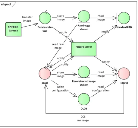
Since SPIFFIER is an Integral Field Spectrograph, the raw frames coming out of the science detector contain the spectra for each of the 32×32 spaxel. In order to support target acquisition procedures and to have a visual feedback about the status of the observation, it is required to reconstruct an image of the target from the IFS frames. The Quick-Look component is in charge of this operation.
The architecture of the SPIFFIER Quick Look is illustrated in Figure 4. Science frames coming from the SPIFFIER camera are transferred by NGC data transfer task into “raw image” shared memory, from which they can be displayed using the VLT standard Real Time Display (RTD) application. Raw frames are also taken from shared memory by the “spoql” process which applies a simplified version of SPIFFIER data reduction pipeline to produce a 32×32 reconstructed image, which is then stored in the “reconstructed image” shared memory from which it can be displayed using the “sportd” application. The latter is a customized version of the standard RTD, with the addition of widgets and menu entries which allow the user to control the quick-look process. The necessary exchange of messages to notify the availability of data is mediated by the “rtdcore server” process.
4.5 QACITS
For observations in Focal Plane Coronagraphy (FPC), NIX will employ a vortex phase mask. Since such mask is very sensitive to target de-centering errors it is necessary to perform on-line measurement of de-centering and apply corrections. “QACITS Manager” is the component in charge of the measurement, using the QACITS technique12, while
the correction is applied by the Secondary loops and offloads component.
QACITS manager is directly commanded by FPC templates. The algorithm is set-up during target acquisition, when background, coronagraph reference position and target PSF are measured. During observations the component is commanded to analyze science frames and estimate that target shift w.r.t. the coronagraph. This data is then written in the on-line database, from which it is then retrieved by Secondary loops and offloads component to perform a correction.
sd spoql SPIFFIER Camera rtdcore server Standard RTD sportd Raw image shmem Reconstructed image shmem spoql Data transfer task OLDB transfer image store image read image read configuration write configuration CCS message read raw image read image notify notify notify notify notify store image
Figure 4: SPIFFER Quick Look software architecture.
The QACITS manager is currently being implemented. Luckily enough, the VLT2017 release of the VLTSW framework has added support for control tasks written in Python and the team which devised the QACITS technique has a working implementation in that language. Therefore, the component is being written in Python, instead of the more “traditional” C++ language, and we expect that this will greatly reduce development and testing times.
4.6 Phase-Sorting Interferometry
For all High-Contrast Imaging (HCI) AO-assisted observations with NIX, it is foreseen to offer the possibility of using Phase Sorting Interferometry13 to suppress quasi-static speckles and other residual diffraction halo.
When required, the process will be commanded by templates. The observing template will take care of starting slopes recording in SPARTA before starting the science exposure. At the end of the exposure, the template will retrieve the recorded slopes and pass them to PSI Manager component together with the image data, which will be stored in cube mode (i.e. containing all individual integration frames). Actually, only file names will be passed, for efficiency. PSI Manager will then combine slopes data with individual integration frames to compute delta-slopes to correct for residual, semi-static, speckles and will store them to disk. The template will apply the delta-slopes in SPARTA at the end of the ongoing exposure (or immediately if no exposure is running).
Also in this case, the implementation of the component will be done in Python, leveraging the existing algorithm implementation is the same language performed by the group which developed the PSI technique.
5. SOFTWARE ENGINEERING
The software development process for ERIS is the typical one adopted for VLT instruments: a waterfall-like approach for the initial phases, up to Final Design Review, and an incremental delivery approach during the “manufacturing” phase.
In the initial, or preliminary design, phase, the main goal has been the collection of user requirements and their analysis, to produce an architectural design. The main deliverables for this phase were the Instrument Software User
Requirements (ISURS) and the Functional Specification (ISFS) documents, which were submitted for review at the Preliminary Design Review milestone, together with a preliminary version of the Templates Manual.
In the detailed design phase, the user requirements and architectural design were consolidated, and each component has been designed, specifying functions and algorithms. Software interfaces with external systems were defined and mock-ups of user interfaces were produced. Procedures were also defined which specified which software must be tested and how. Besides updated versions of the PDR documents, at the end of the design phase the Instrument Software Design Description (ISDD) and the Acceptance Test Plan (ATP) were also produced. Also, a skeleton of the Instrument Software was developed, by adapting a template provided by ESO and containing only configuration information but no ERIS specific code. These deliverables were submitted for the Final Design Review, which took place successfully in May 2017.
After FDR, the actual implementation of the software has started, building upon the skeleton prepared for the review, by completing the configuration, developing templates and the software components. The ERIS INS is kept under revision control using ESO subversion repository. We adopted a “stable trunk” branching model, meaning that the trunk of development should always build and pass automated tests successfully. Developers are allowed to modify the trunk only for small changes, while any non-trivial development shall take place in a branch, which is then re-integrated after checking that it builds and pass tests.
The stability of trunk is checked automatically by means of the ESO Jenkins14 Continuous Integration system. The
system is set-up to perform a complete re-build of the software and execute automated tests every night. Any modification that “breaks the build” is reported by Jenkins via email, so that it can be corrected quickly.
Support for sub-system and system integration will be provided by creating a dedicated branch, tailored for each specific configuration of hardware available at the [sub-]system integration site. Such branch will be installed in the target system following a well-defined procedure, which includes a backup of the existing installation to allow for a quick roll-back in case of problems and an initial functional testing. After that the branch is tagged, to keep track of the initial configuration. Any issue with a specific software installation will be reported using an internal ticketing system (trac15)
to ensure that they’re followed-up properly. When the branch is stable, i.e. no modifications are requested, or issues reported, it is merged back in trunk and a tag is created, to clearly mark a tested and working configuration.
6. FINAL REMARKS
The ERIS instrument is a quite complex facility, featuring a calibration unit, two science channels and an Adaptive Optics module that will take advantage of VLT UT4 Adaptive Optics Facility, i.e. Deformable Secondary Mirror and the Four Laser Guide Stars Facility. ERIS is also meant to be a “workhorse” instrument and therefore offers many observing modes, with the corresponding need for calibration and maintenance procedures.
In this paper, we have presented the design of the ERIS Instrumentation Software, which is currently being implemented and that will soon begin to “meet the hardware” when the instrument sub-systems will start being integrated. On the basis of our past experience with AO-assisted instrumentation for the VLT16, we think that the ERIS INS design is
adequate to provide all the need functionalities and required performance to properly support instrument operations.
REFERENCES
1. Davies, R., et al., “ERIS: revitalising an adaptive optics instrument for the VLT,” Proc. SPIE 10702 (2018).
2. Madec, P.-Y., et al, “Adaptive Optics Facility: control strategy and first on-sky results of the acquisition sequence,” Proc. SPIE 9909 (2016).
3. Pearson, D, et al., “NIX, the imager for ERIS: the AO instrument for the VLT,” Proc. SPIE 9908 (2016).
4. George, E. M., et al, “Making SPIFFI SPIFFIER: Upgrade of the SPIFFI instrument for use in ERIS and performance analysis from re-commissioning,” Proc. SPIE 9908 (2016).
5. Eisenhauer, F., et al, “SINFONI - Integral field spectroscopy at 50 milli-arcsecond resolution with the ESO VLT,” Proc. SPIE 4841 (2003).
6. Dolci, M., et al, “Final design and construction of the ERIS calibration unit,” Proc. SPIE 10702 (2018). 7. Riccardi, A., et al, “The ERIS adaptive optics system: from design to hardware,” Proc. SPIE 10703 (2018).
8. Kiekebusch, M. J., et al, “PC based PLCs and ethernet based fieldbus: the new standard platform for future VLT instrument control,” Proc. SPIE 9152 (2014).
9. Baade, D., et al, “NGC — ESO's New General Detector Controller,” The Messenger 136, 20-24 (2009). 10. Suárez Valles, M., et al, “SPARTA for the VLT: status and plans,” Proc. SPIE 8447 (2012).
11. Duhoux, P., et al, “VLT instruments: industrial solutions for non-scientific detector systems,” Proc. SPIE 9152 (2014)
12. Huby, E., Baudoz, P., Mawet, D., Absil, O., “Post-coronagraphics tip-tilt sensing for vortex phase masks: the QACITS technique,” A&A, 584, 74 (2015).
13. Codona, J., Kenworthy, M. A., Lloyd-Hart, M., “A novel WFS technique for high-contrast imaging: Phase Sorting Interferometry (PSI),” Proc. SPIE 7015 (2008).
14. https://jenkins.io/ 15. https://trac.edgewall.org/