HAL Id: hal-02140520
https://hal.archives-ouvertes.fr/hal-02140520
Submitted on 27 May 2019
HAL is a multi-disciplinary open access archive for the deposit and dissemination of sci-entific research documents, whether they are pub-lished or not. The documents may come from teaching and research institutions in France or abroad, or from public or private research centers.
L’archive ouverte pluridisciplinaire HAL, est destinée au dépôt et à la diffusion de documents scientifiques de niveau recherche, publiés ou non, émanant des établissements d’enseignement et de recherche français ou étrangers, des laboratoires publics ou privés.
Time-of-flight angiography at 7T using TONE double
spokes with parallel transmission
Gaël Saïb, Vincent Gras, Franck Mauconduit, Nicolas Boulant, Alexandre
Vignaud, Pierre Brugieres, Denis Le Bihan, Laurent Le Brusquet, Alexis
Amadon
To cite this version:
Gaël Saïb, Vincent Gras, Franck Mauconduit, Nicolas Boulant, Alexandre Vignaud, et al.. Time-of-flight angiography at 7T using TONE double spokes with parallel transmission. Magnetic Resonance Imaging, Elsevier, In press, �10.1016/j.mri.2019.05.018�. �hal-02140520�
Time-of-flight angiography at 7T using TONE double
spokes with parallel transmission
Saïb Gaël1, Gras Vincent1, Mauconduit Franck2, Boulant Nicolas1, Vignaud Alexandre1, Brugières
Pierre3, Le Bihan Denis1, Le Brusquet Laurent4, Amadon Alexis1*
1 CEA/DRF/Joliot/NeuroSpin, Université Paris-Saclay, 91191 Gif-sur-Yvette, France 2 Siemens Healthcare, 40 avenue des Fruitiers, 93210 Saint-Denis, France
3 Department of Radiology, AP-HP, CHU Henri Mondor, 94000 Créteil, France
4 Laboratoire des Signaux et Systèmes (UMR CNRS 8506), CentraleSupélec, Université Paris-Saclay, 91190 Gif-sur-Yvette, France
* Corresponding author: alexis.amadon@cea.fr at CEA-Saclay, NeuroSpin, Bât. 145, 91191 Gif-sur-Yvette Cedex, France.
Abstract
:
Purpose: To demonstrate that fast-k
z spokes can be used in parallel transmission tohomogenize flip angle ramp profiles (known as TONE) in slab selections, and thereby
improve Time-Of-Flight angiography of the whole human brain at 7T.
Methods:
𝐵1
+and 𝐵0 maps were measured on seven human brains with a z-segmented coil
connected to an 8-channel pTx system. Tailored two-spoke pulses were designed under strict
hardware and SAR constraints for uniform slab profile before transforming their subpulse
waveforms for linearly-increasing flip-angle ramps. Increasing angulations along the
feet-head direction were prescribed in 2-slab and 3-slab TOF acquisitions. Excitation patterns
were simulated and compared with RF-shimmed (single spoke) ramp pulses. Excitation
performances were assessed in ~10-min TOF acquisitions by visually inspecting Maximal
Intensity Projections angiograms.
Results: The flip-angle ramp fidelity achieved by double spokes inside slabs of interest was
improved by 30-40 % compared to RF-shimmed ramps. This allowed better homogenizing
signal along arteries, and depicting small vessels in distal areas of the brain, in comparison
with RF-shimmed ramp pulses or double-spoke uniform excitation.
Conclusion: Ramp double spokes used in conjunction with parallel transmission yield better
blood saturation compensation and more finely resolved TOF angiograms than mere double
spokes or ramp single spokes at 7 T.
1. Introduction
Time-Of-Flight Magnetic Resonance Angiography (TOF-MRA) is advantageous at 7T compared to lower field MRI as it benefits from longer T1 relaxation time and thus from a better vessel-to-background contrast [1]. In addition, the major asset of ultra-high field (UHF) scanners remains their capacity to provide higher signal-to-noise ratio (SNR) [2] which can be used to increase the image spatial resolution. Thus, the use of 7T imagers enhances the sensitivity of TOF angiograms and improves by the same token the depiction of vascular abnormalities such as stenosis, small aneurysms and microvascular diseases [3–11].
Non-contrast-enhanced TOF is a non-invasive technique and the most widely used MRA sequence for intracranial applications. Nevertheless, it is sensitive to spatial RF heterogeneities inherent to the 𝐵1+ field propagation at UHF, preventing fine visualization of the whole intracranial vasculature. Yet, the use of fast-k𝑧 spokes [12] to perform slice-selective excitations have proven very useful to flatten the in-plane flip angle (FA) distribution, especially with parallel transmission (pTx) [13]. Their use outperforms the more conventional static RF shimming to mitigate the transmit field heterogeneity at 7T [14]. The goal of this study is to design and assess tailored pTx spokes that not only homogenize the in-plane FA distribution, but also target FA ramp profiles, such as achieved by Tilted Optimized Non-saturating Excitation (TONE) pulses commonlyused in TOF, as discussed below.
Multiple Overlapping Thin Slab 3D Acquisition (MOTSA) efficiently reduces the blood saturation effects in TOF MRA [16], by splitting the acquisition in several thin slabs. As the number of separately-acquired slabs increases, residual overlapping between adjacent slabs typically produces venetian blind artefacts, affecting the vessels visualization. As shown previously [17], TONE [18–21] minimizes these drawbacks by allowing thicker slabs and less overlap. TONE consists in generating a linearly-increasing flip angle profile through the slab, with an initial FA and a slope presumably adapted to the thru-slab component of the arterial blood velocity 𝑣⊥ [22]. The FA ramp slope is adjusted to restore as much as possible a homogeneous blood signal along the vessels, and thereby between the slabs.
TOF is very sensitive to blood dynamics and intra-voxel signal dephasing. In particular, pulsatile flow in regions involving strong susceptibility ∆𝐵0 inhomogeneities tends to accentuate intra-voxel dephasing conducive to signal intensity losses [27]. To avoid misleading interpretations, the echo time TE has to be minimum and the use of gradient moment nulling techniques is highly recommended [29].
As suggested by Schmitter and colleagues [14], the goal of the following work is to enhance TOF imaging capacities at 7T by compensating blood saturation with TONE pulses based on spokes using pTx, and to compare resulting Maximum Intensity Projection (MIP) images on the whole human
brain with those obtained from static RF shimming. These spoke pulses are meant to counteract RF heterogeneities which hamper the desired TONE profile in order to make the flowing blood signal as uniform as possible [26]. For this purpose, the following study presents a slab selective spoke design optimized under SAR constraints, ensuring an optimal power control of the radiofrequency field.
2. Methods
2.1. Parallel-transmission ramp spoke design
Multi-spoke RF pulses consist in successive selective excitations [12], i.e. series of identical symmetrical sub-pulse shapes (typically sinc shapes) and their associated slice or slab selection gradient waveform, interleaved with magnetic field gradient blips in the slice in-plane directions (cf. Fig. 1). For TOF, slab selection is performed along the z magnet axis so as to capture arterial blood inflow from the bottom to the top of the brain. The design of a multi-spoke RF pulse hence consists in determining a set of spoke locations and RF coefficients that allows approaching a desired FA profile (𝜃𝑡𝑎𝑟𝑔𝑒𝑡) with the highest fidelity.
For multiple-spoke excitations, the starting point of TE becomes unclear as peaks of RF energy are spread out in time. In this study, the center of the multiple-spoke window is picked as the start of TE. As seen earlier, it is important to minimize TE, therefore shorten the RF pulse length as much as possible, which will minimize T2* decay during excitation. Thus, only two spokes were considered to address the FA fidelity problem for each slab.
Since the FA range in TOF sequences does not exceed 40°, the spoke RF coefficients (vector 𝒃 of complex weights each addressing a transmit channel) could be designed under the small tip angle approximation (STA) using the spatial domain method [31]. In this framework, the relationship between the flip angle map 𝜽 and the RF coefficients is linear: 𝜽 = 𝑨𝒃 where matrix 𝑨 encodes the in-plane components of the k-space trajectory, the 𝐵1+ maps for each transmit channel and the 𝐵0 offset (𝐵0) distribution. The spoke problem usually addresses a 2D slice where in-plane uniformity is targeted. Here the addressed region of interest consists in all voxels located in the selected slab, regardless of their z-component. Let 𝜃𝑡𝑎𝑟𝑔𝑒𝑡 be the desired FA in the center of the slab profile. We separate our spoke problem from the FA ramp production, and first solve the former by considering uniform excitation, i.e. 𝜃𝑡𝑎𝑟𝑔𝑒𝑡 is also the target in the entire slab.
Let (𝑘𝑥, 𝑘𝑦) be the coordinates of the 1st spoke, the second spoke going through the center of
k-space. To optimize the 𝒃 complex coefficients along with (𝑘𝑥, 𝑘𝑦) as in [32,37], a two-step procedure was used:
Figure 1 : Pulse diagrams for 1-spoke and 2-spoke excitations (top) and their associated k-space trajectory (bottom). The selection gradient G is represented in black in the pulse time chart. On the right, the vertical spokes (black lines 1 and 2) in transmit k-space are played along with the RF waveforms whereas the (kx, ky) location of the first spoke is induced by the
(Gx, Gy) gradient blips respectively in blue and orange.
Step 1: given an initial choice for (𝑘𝑥, 𝑘𝑦), an initial value for 𝒃 was obtained by numerically solving the optimization problem:
min
𝒃 ‖|𝑨(𝑘𝑥, 𝑘𝑦)𝒃| − |𝜃𝑡𝑎𝑟𝑔𝑒𝑡|‖2 2
+ 𝜆‖𝒃‖2 (1)
where 𝜆‖𝒃‖2 is a Tikhonov regularization term with 𝜆 adjusted for the RF peak amplitude constraint fulfillment. This magnitude least squares (MLS) problem is solved using the Variable Exchange method (VEM) [33,34].
Step 2: The optimal value for 𝒃 returned by the previous optimization is then used to initialize the full MLS problem:
min 𝑘𝑥,𝑘𝑦,𝒃
‖|𝑨(𝑘𝑥, 𝑘𝑦)𝒃| − |𝜃𝑡𝑎𝑟𝑔𝑒𝑡|‖2
2 (2)
which is solved under explicit constraints with regards to the RF peak amplitude, average power, global and peak local SAR limitations [35,36] (thresholds given below).
radius were set as initializations of these two-step local optimizations. Indeed, by retaining the best candidate as the optimal solution, 20 initializations are deemed sufficient to reach the global optimum with more than 99% probability [32,37].
As the addressed problem is two-dimensional (no degree of freedom along kz), a uniform FA
was chosen for the target inside the entire ROI, namely the target FA corresponding to the center of the selected slab in a linear ramp configuration. The resulting excitation was then made a TONE pulse by assigning pre-computed ramp sub-pulse waveforms to the spokes. These RF waveforms were obtained by multiplying the frequency response of a conventional sinc with the desired ramp, and by taking the inverse Fourier transform of the resulting product [26,38].
The optimization problem [see Eq. (2)] was numerically solved using the Active-Set algorithm from Matlab (MathWorks, Natick, MA). In compliance with the IEC guidelines [39], local and global SAR limits of 10 W/kg and 3.2 W/kg were respectively enforced at the spoke pulse design stage. RF pulses were generated separately for each slab using an apodized TONE sub-pulse waveform with a time-to-bandwidth product of 10, a maximum average power of 6 W per channel, and a maximum peak voltage of 160 V per channel. Considering peak power limitations, sub-pulse durations could be decreased to 0.8 ms for 2 spokes. For a fair comparison between static RF shim and double-spoke design, the static RF-shimming single spoke duration was set to 1.6 ms. However, for this duration, the conventional circularly polarized (CP) mode could not reach the specified FA anywhere in the human head due to the peak local SAR constraint saturation. Furthermore, the CP mode is known to yield poor RF homogeneity in the head at UHF. Therefore, the study essentially focused on a comparison between RF-shimming and TONE double-spoke excitations (Fig. 1). The double-spoke excitations were designed with an alternating polarity gradient allowing to reduce the pulse length compared to monopolar schemes. For the double-spoke pulses, the gradient delay reported in [40] was handled by delaying the RF waveforms by 2.69 𝜇s.
Even though the STA was used to optimize both spoke locations and RF coefficients, resulting FA-maps were simulated from the ramp RF waveforms using numerical integration of the Bloch equations. The performance of the pulse was then measured as the voxel-wise root mean square error from the ramp target FA profile, normalized to the desired average FA across the slab:
NRMSE (%) =100. √∑(𝜃𝐵𝑙𝑜𝑐ℎ− 𝜃𝑑𝑒𝑠𝑖𝑟𝑒𝑑) 2 √𝑁𝑣. 〈𝜃𝑑𝑒𝑠𝑖𝑟𝑒𝑑〉
(3)
where 𝑁𝑣 is the number of voxels contained in the slab selection, and 𝜃𝑑𝑒𝑠𝑖𝑟𝑒𝑑 is now the z-dependent desired FA ( 〈𝜃𝑑𝑒𝑠𝑖𝑟𝑒𝑑〉 = 𝜃𝑡𝑎𝑟𝑔𝑒𝑡). This NRMSE index may later be referred to as FA-ramp fidelity, or simply FA fidelity.
measured FA maps obtained on a spherical water phantom using the AFI B1-mapping sequence [42].
2.2. Experimental set-up and TOF protocol
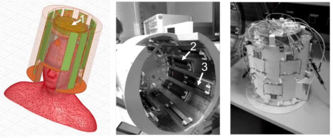
The experiments were performed on a 7 Tesla (T) scanner (Magnetom, Siemens Healthcare, Erlangen, Germany) equipped with an eight-channel pTx system and AC84 head gradient system (50 mT/m maximum amplitude and 333 T/m/s maximum slew rate). Transmission and reception were carried out using a homemade 12-Tx/22-Rx head array including a circularly-polarized (CP) transceiver patch close to the top of the head and 11 azimuthally-distributed transceiver dipoles segmented in two rows along the z-direction (Fig. 2). According to a previous study [41], this coil demonstrated higher 𝐵1+ enhancement potential away from the isocenter in the z direction, easing the pulse design performance in comparison with a non-segmented transmit-array commercial head coil. Seven healthy volunteers aged 27 ± 7 years (5 men, 2 women, height: 1.68 – 1.82 m, weight: 60 – 98 kg) were scanned with this equipment under local SAR supervision. The study was approved by an Institutional Review Board and all subjects signed an informed consent form. Each experiment included two second-order 𝐵0 shimming iterations, a calibration step, a fast sagittal phase-contrast localizer, offline RF pulse computations and multi-slab TOF acquisitions. The calibration step consisted in the acquisition of eight individual channel-specific 3D 𝐵1+ maps (in T/V) using the XFL sequence (PreSat FLASH) in an interferometric fashion (5 mm isotropic resolution, matrix size 40 x 64 x 40, TR = 20 s, TA = 4 min) [43–45]. Additionally, the 𝐵0-map was measured using a 3D GRE sequence (2.5 mm isotropic resolution, matrix size 80 x 128 x 80, echo times TE = 4.6/6.3/8 ms, TR = 25 ms, TA= 2 min 56 s). Magnitude of the first echo was used to generate the brain mask required for the pulse design thanks to the Brain Extraction Tool from FSL [46]. Yet for RF pulse design, the 𝐵0 -map resolution was downgraded to that of the 𝐵1+-maps.
Figure 2 : Homemade 12-Tx/22-Rx z-segmented head array. The coil includes a patch element (1), eleven z+ (2) and z- (3) dipoles azimuthally distributed to improve the spatial homogeneity of the RF transmission in the whole head. In addition to
Then not all subjects underwent the exact same acquisitions as some piloting and tuning was required, in particular to determine pseudo-optimal TONE ramp slopes. In the end, only three subjects were scanned with stable TOF acquisition parameters presented next. Two multiple-slab
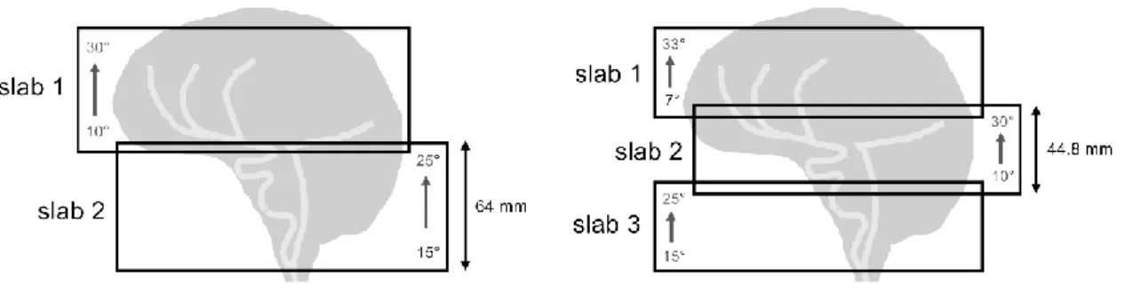
configurations were investigated to cover the whole arterial brain: two 64-mm slabs and three 44.8-mm slabs respectively overlapped by 15% and 18% for TA=10 min and 11 min 5 s (Fig. 3). In a typical clinical context, for the sake of simplicity and rapidity, the same linear ramp is used for every slab. Here we attempted to optimize slab-assigned ramp slopes, since the higher the slab, the slower the arterial blood velocity is expected along z. The ascending FA target profiles were empirically chosen with increased slopes from the bottom to the top of the head. The specified FA was set to a reference of 20° in the centers of the slabs. Thus, optimal slopes found for 2-slab acquisition were 15° to 25° in the feet-head direction for the bottom slab, and 10° to 30° for the top slab. For three slabs, identical 15°-25° and 10°-30° angulations were chosen for the bottom and middle slabs while the highest slab was addressed with a steep slope varying from 7 to 33°. All ramped flip angle assessments are illustrated in Fig. 3 for the two configurations used in this study.
After the calibration process, pTx RF pulses were computed on the fly for each corresponding multi-slab scenario using the spoke method previously described. They were then integrated into a modified pTx TOF sequence where the slabs were reordered to be sequentially played from the top to the bottom of the head (i.e. against flow direction), avoiding potential inter-slab arterial blood
saturation effects. To evaluate the double-spoke benefit to compensate for 𝐵1+-inhomogeneities, each slab selection was benchmarked with a TONE single-spoke design (RF shimming). Thus, to cover the 2-slab and 3-slab configurations, a total of 10 tailored pulse designs had to be run after patient
calibration.
Figure 3 :2-slab and 3-slab TONE angulations. Linearly ascending flip angle profiles were addressed from the bottom to
the top of each slab. The overlapped region was 15% (18%) for the 2-slab (3-slab) configuration covering 118.4 mm. Acquisitions were carried out sequentially from the top to the bottom of the head to avoid inter-slab blood saturation effects.
The three-dimensional TOF sequence was acquired as MOTSA [16] and the whole-brain MIP image merged by the scanner reconstruction algorithm. Each slab selection was set 5-mm thicker than the imaged portion to keep away from signal dropouts at the edge of the slab. This forced the use of a slice oversampling of 37% to avoid aliasing issues. Three of the seven subjects were scanned with
2-slab and/or 3-2-slab configurations (Fig. 3) and the following imaging parameters: TR = 20 ms, TE = 3.14 ms, asymmetric echo = 36%, resolution: 0.4 x 0.4 x 0.8 mm, FOV = 200 x 200 x 118.4 mm, GRAPPA acceleration factor 4 in the phase encoding direction (right to left) and readout bandwidth = 511 Hz/px. Moreover, to prevent ghosting artefacts and signal losses in turbulent flows, first-order flow compensation gradients were used in the slice and phase directions.
2.3. SAR management
For the sake of the volunteers’ safety, validation of our home-made pTx coil with respect to SAR control has been the subject of an internal procedure at NeuroSpin, approved by both an external review board and ANSM (French National Safety Agency). The description of the validation
procedure is provided in [58].
Siemens pTx system at 7T allows monitoring the amplitude and phase of the RF signals dispatched on the Tx-array, enabling local and global SAR evaluation in real-time. The dedicated Siemens software calculates the peak 10-g SAR in real-time based on the measured waveforms. The calculation relies on Virtual Observation Points (VOPs) [59] that we provided to the scanner. We computed VOPs from the result of HFSS (Ansys, Canonsburg, PA) simulations of two numerical home-made head models (1 male [60] + 1 female [61]) placed in our RF coil. The mean error between simulation and measurement of B1+ maps on a phantom of known dielectric properties propagated into
a 1.4 safety margin accounting for model/measurement discrepancies. Additional safety factors were applied to the VOPs to account for inter-subject variability (1.4 factor), and waveform monitoring uncertainty (1.21 factor).
3. Results
3.1. Single versus double spoke ramp excitations
Comparing in Fig. 4 FA profile simulations of a representative subject for the different TONE pulses, the optimized double-spoke showed better FA fidelity than a single spoke. Static RF shimming (single spoke) indeed seemed not sufficient to restore acceptable FA homogeneity as it generates destructive RF interferences in the bottom slab (blue region in Fig. 4a). Calculation for two spokes took about 2 minutes whereas just a few seconds were needed for the single-spoke computation. For the static RF shim (1.6-ms pulse duration), we found that the saturation of the peak RF power and local SAR constraints (cf. Supplementary Information Table 1) severely limited the performance of the single spoke and explained the B1+ drop in Fig. 4a. This was not recoverable by relaxing the
Figure 4 :Sagittal and transversal slice views of the simulated FA maps for TONE single and double spoke (for subject 1).
FA ramps were established for 2 slabs as specified in Figure 2. For each excitation type (a and b), the top row displays the axial FA patterns of the top slab from feet to head while the bottom row shows the FA patterns for the bottom slab. The TONE double spoke (b) generated a more uniform thru-slab profile compared to TONE single spoke (a). Top slab FA-NMRSE for single and double spoke was respectively 19.5% and 13.4%. In the bottom slab FA-FA-NMRSE was 28.5% for single spoke and 20% for double spoke excitations. Note that the 1-D FA profiles shown at left follow a vertical line in the center of the sagittal profile. The slab profiles obtained for double spokes showed better fidelity to the ramp desired profiles (grey line) compared to single spoke. The slab profiles overlap by 15%.
Figure 5 : Statistical comparison of TONE single- vs double-spoke FA-fidelity based on the set of seven subjects. Box plots of the FA-NRMSE estimated on seven subjects for 2-slab (a) and 3-slab (b) configurations. The edges of the box indicate the 25th and 75th percentiles while the cross and central marks represent the mean and median FA-NRMSE, respectively. Whiskers show minimum and maximum FA-NRMSE. This distribution denotes a good inter-subject pulse design reproducibility.
drop occurred in the lower slab of all 7 subjects. As a result, in the 2-slab selection, the average FA-NRMSE [see Eq. (3)] dropped by 35.5 % when replacing the RF-shimmed spoke by the double-spoke excitation, given identical pulse total durations and power/SAR constraints. This is shown in Fig. 5, which depicts a quantitative analysis of the FA-NRMSE values computed after pulse design for the chosen TOF slabs in all subjects. In the 3-slab selection, the average improvement of the slab FA-fidelity with double spokes is 31.1 %, with a record gain of 38.6 % for the middle slab (cf. Fig. 5b).
Native TOF images of Subject 1 in Fig. 6.a corroborated these observations showing that double-spoke pulses improve the saturation uniformity of surrounding tissues compared to the signal heterogeneities visible in the RF-shim acquisition. Corresponding angiograms acquired with TONE double spokes also demonstrated better contrast and spatial homogeneity in comparison to single spokes, improving the MIP background-to-vessel contrast, as shown in Figs. 6.b-c. Although depiction of posterior arteries was more noticeable for the RF-shim, the destructive RF interferences located near the carotid siphon induced local signal loss affecting the internal carotids and basilar artery. Indeed, the inflowing blood experienced little excitation in the upstream basilar region impacted by the local RF interference. As mentioned earlier, this B1-drop phenomenon in RF-shim occurred in all
subjects. Supplementary Information Fig. 1 gives another instance of poorly-shimmed B1-maps and of
how this affects associated TOF angiograms compared to clean double spoke excitations.
Figure 6 :Comparison of TONE single vs double spoke for native TOF images (a) and corresponding maximal intensity projection (MIP) angiograms (b). As shown in the corresponding FA maps (Figure 4), in the bottom slab, a linear varying
FA of 15-25° in the feet-head direction was addressed, while a 10-30° FA profile targeted the upper slab. Double spoke excitations yield better signal homogeneity and fat signal attenuation in comparison to single spoke. Notice how the single-spoke RF destructive interference impacted the carotids and basilar artery (yellow arrows). Also notice a « third arm artifact » in the temporal lobe on the native images - hypersignal on the left in (a) - due to the z-limited extent of the AC84 gradient head coil linearity: excited protons in the neck/shoulders region fold back into the image. As the excitation scheme differs between (a) and (b), so does the artifact. At last, (c) depicts signal profiles along the colored lines in the coronal view. Notice how the double spoke recovers contrast between arteries and the brain parenchyma, especially in the lower slab.
3.2. Blood saturation compensation with TONE double spokes
Different angulations were experimentally addressed in order to determine the best TONE ramp for each slab. It has been observed that in the lower slab, too steep FA slopes lead to weakened FA at the slab inlet, therefore a detrimental impact on the carotids and vertebral arteries signal located in this region. Hence, 15°-25° was considered as the optimal angulation for the range of blood velocity and for the arterial vasculature anatomy in this region. Supposing a lower arterial velocity in the upper slab, a steeper angulation of 10°-30° was addressed in this selection (cf. Fig. 7c-d). This substantially improved the distal arteries conspicuity, as well as the middle cerebral arteries (MCA) and anterior cerebral arteries (ACA) visualization. Overall it improved the global signal homogeneity along the vessels. The same slope shifted to 30° at the center of the slab (Fig. 7b) accentuated blood saturation effects, justifying the 20° FA reference.
Figs. 8 and 9 compare the effect of conventional (sinc) double-spoke uniform excitation (UE) with that of TONE double spokes on FA maps and partial MIPs respectively, for the third subject. While most FA profiles look faithful to their target, the MIPs in Fig. 9 confirm the soundness of TONE to recover some arterial signal, as can be observed for example in the right temporal lobe or the posterior part of the brain in the 2-slab configuration.
Also, as can be seen on the whole brain MIP in Fig . 10, the TONE double spoke applied in this configuration improves the vessels conspicuity in both slabs, as well as blood signal uniformity. However, from Figs. 7, 9 and 10, it can also be noticed that the continuity of some small arteries is lost at the slab interface. This shows the main limitation of TONE pulses, known to yield a stronger saturation of blood vessels oriented in-plane, especially close to the upper edge of the slab. Moreover, TONE induced inevitable non-uniform contrast across the slabs arising from the increasing level of saturation of static tissue in the background, increasing the visibility of their junction. This was not detrimental to image interpretation.
As can be appreciated in Fig. 6b, the superior sagittal venous sinus appears saturated in the upper slab compared to the bottom slab where its confluence with the transverse sinus is visible. Indeed, venous flow experienced more RF pulses in the upper slab enabling stronger venous
saturation. Moreover, the effect of the TONE profile on the venous system allowed to accentuate the venous saturation. This observation was similar for all subjects in the study, as can be seen in the Supplementary Information Fig. 2.
3.3. Two versus three slabs
Retrospective TONE double-spoke pulse designs comprising the seven pilot subjects were independently conducted for 2-slab and 3-slab selections. TONE waveforms resulted in a mean
NRMSE of 18% and 10% respectively for the bottom and top slab of the 2-slab configuration, and 21%, 16% and 8%, for the bottom, middle and top slab of the 3-slab configuration (Fig. 5). These results demonstrate the pulse design method robustness and yet the difficulties to yield the desired FA pattern in the lowest slab suffering from 𝐵1+ losses and high ∆𝐵
0 heterogeneities. In contrast, in both configurations, the pulse design achieved FA profiles closer to target in the higher region where B0 and B1 inhomogeneities are not as severe. Yet it is worth mentioning faithful ramps were also
facilitated in the highest slabs by the z-segmentation of the coil, which includes a patch element at the top of the head allowing maximizing the 𝐵1+ magnitude therein (cf. Fig. 2 and ref. [41])
TONE simulated FA maps of the third subject (Fig. 8) and their associated TOF angiograms (Fig. 11) allow comparison of 2-slab and 3-slab acquisitions covering exactly the same volume. FA profiles close to linear target were indeed fulfilled with TONE double spokes in both configurations, although the bottom slab was particularly hard to address in the 3-slab design.
Figure 7 : Effect of different FA ramp profiles on blood saturation. Sagittal MIP of the top slab selection for double spokes addressing a uniform 20° FA (a), a TONE FA pattern 20-40° (b) and 10-30° (c) in the feet-head direction. The latter provides better vessel-to-background contrast as can be appreciated in the one-dimensional anterior-posterior signal profile
(d). Shifted 20-40° ramp (green line) tends to increase blood saturation, reducing arterial signal. In contrast, the 10-30° ramp (blue line) enhanced the blood signal intensity compared to a flat 20° profile (orange line).
Figure 8 :Simulated FA maps of 2-slab and 3-slab 2-spoke UE and TONE. Sagittal and transversal views of the 2-slab (a)
and 3-slab (b) FA Bloch simulations for representative subject #3. FA ramps were chosen as in Figure 2. Note that the TONE profile was more challenging to generate in the lower slab.
Figure 9 : 2-slab and 3-slab TOF acquisitions for 2-spoke UE and TONE. Sagittal 70 MIP and coronal zoom 30 mm-MIP images for 2-slab and 3-slab TOF acquisitions using the excitations simulated in Figure 8 (subject #3). In the middle slab, the MCA were more impacted by saturation effects, and TONE compensation was more challenging in this region (white arrows). In the upper slab, the ascending ramp of 7-33°compensated ACA and MCA signal saturation more efficiently allowing further small arteries visibility in comparison with the 2-slab acquisition.
Figure 10 : Full MIP for axial, sagittal and coronal views using double spoke uniform excitation (UE) and TONE for 2
slabs for subject #1. As indicated by the white arrows, TONE RF pulses provided higher signal intensity in the polygon of
Willis region and distal arteries. Signal intensity was increased in MCA and ACA, resulting in additional small arteries depiction. Subcutaneous fat and obvious signal venous signal were manually removed to better appreciate the arterial network.
Figure 11 : 2-slab and 3-slab TOF acquisitions for TONE double spokes. Sagittal 70-mm MIP, coronal 70-mm MIP, and axial full MIP images for 2-slab and 3-slab TOF acquisitions of subject #2 (excitations simulated in Figure 8). In the middle slab, the MCA were more impacted by saturation effects, and TONE compensation was more challenging in this region (yellow arrows). In the upper slab, the ascending ramp of 7-33°compensated ACA and MCA signal saturation more efficiently allowing further small arteries visibility in comparison with the 2-slab acquisition. In this case, the MIP contrast was reduced in the slab inlet region due to the low FA in this region.
As expected, in the 3-slab acquisition, the venetian blind artefacts and the signal from venous vessels were accentuated in comparison with the 2-slab acquisition. Even though, the peripheral vasculature and posterior arteries were relatively better depicted in the full MIP since the reduced thickness of the slabs tends to prevent non-perpendicular flow saturation (cf. posterior halves in Fig.11 axial views). The application of 3-slab TONE provided a better visualization of small arteries,
especially in distal regions eased by a satisfying contrast uniformity. However, in this case, the 10-30° slope of the middle slab could not completely restore the vessel continuity between the middle and top slabs. Also, the steep slope 7-33° in the upper slab highly impacted the background signal as the FA was particularly low in the inlet region. Yet this did not compromise image interpretation. Although the overall arterial vasculature visibility was slightly improved within the 3 slabs, , disruptive junctions were more pronounced and venous signal more problematic as they polluted the arterial interpretation. The TONE pulses succeeded in attenuating these undesirable effects. Finally, the overall vasculature was more homogenous for the 2-slab acquisition even if some distal arteries were not visible.
4. Discussion
4.1. Recap
This study experimentally demonstrates that the generation of TONE profiles with double spokes to compensate for blood saturation at 7T substantially improves the excitation fidelity compared to more traditional CP mode or single spoke RF shimming. Indeed, homogenizing the B1+
-field with static RF shimming becomes increasingly difficult as the brain region of interest gets wider in the x and y dimensions; then the dynamics brought by double spokes overcomes such difficulties, which explains the record FA-fidelity gain for the central slab in the 3-slab configuration. Therefore, in the configurations used, double-spoke and pTx were essential to carry out quality TONE pulses for TOF experiments at 7T. Also, the pulse design method incorporating explicit hardware (power) and SAR constraints enabled optimal RF solutions with shortening of the RF pulse duration to yield the low TE required for TOF imaging while maintaining an acceptable FA pattern.
4.2. Comparison with state of the art
As already observed by Schmitter et al [14], the double-spoke pulses drastically reduce the subcutaneous fat signal intensity. This is probably due to higher resulting FA in this outer region, saturating the fat signal faster than water (𝑇1 𝑓𝑎𝑡 < 𝑇1 𝑤𝑎𝑡𝑒𝑟) (Fig. 6). In the same study, TOF
angiograms seem to show some additional contrast-to-noise ratio and arteries depiction compared to the present study. This may be due to their choice of thinner slabs – unlike [14], our study intended to cover the whole brain – or because they could use more transmit channels (16 vs 8), easing the FA homogenization. In addition, since our study involved larger slab acquisitions, to make it last less than 12 min, a GRAPPA factor of 4 (vs 2 in [14]) had to be used, detrimental to signal and contrast to noise. Nevertheless, although this present work may not bring the best angiograms at 7T, it shows TONE double spokes can compensate blood saturation while mitigating B1+ inhomogeneities.
4.3. Spokes could have been replaced by k
T-spokes
The use of a z-segmented head array eased the TONE RF pulse design performance in off-centered regions [41]. In a related study, we also demonstrated the advantages of kT-spokes to increase
the RF pulse profile fidelity in a large off-centered selection [38]. This method combines the advantages of spokes [12] and the additional degree of freedom of kT-points [47], enabling the
direction. We would generally advocate the use of this method to improve the pulse design
performance for thick slabs at UHF. However, with our z-segmented coil at 7T, kT-spokes make no
significant difference from mere spokes because of the benefit brought by the extra transmit elements along z.
4.4. Internal carotid signal loss
Despite short TE, the high 𝐵0 offsets around the buccal cavity accentuated intra-voxel dephasing and produced signal void artefacts in the internal carotids region. To counteract such 𝐵0 inhomogeneities, broadband RF pulse design proposed by Setsompop et al. [48] was conducted for a large range of 𝐵0 ([-500; 500] Hz). No significant difference was observed in the final MIP images. Indeed, despite the integration of 𝐵0 maps in the RF pulse optimization problem and the subsequent relative fidelity to the FA target in the regions exhibiting large 𝐵0 offsets, signal losses affect blood in the internal carotids due to intra-voxel dephasing from tremendous 𝐵0 gradients near the buccal and internal sinus cavities. Thus, reducing the TE or the voxel size could alleviate such signal void artefacts. As both of those parameters are antagonist, a tradeoff has to be found. Intra-voxel dephasing was not assessed in this study but could have been taken into account through methods as in references [49,50]. Variable-TE TOF sequences have also proven useful [51]. Moreover, turbulent blood flows are frequently increased in this carotid region behind the mouth due to high velocities, pulsatility and vessels anatomy, which may also translate into arterial signal voids. Then, higher order gradient moment nulling could be a solution but this method generally leads to longer TE.
4.5. Ramp slopes are hard to calibrate
In this study, we have reported the ability of TONE double spokes to improve vessel
uniformity and enhance small-artery conspicuity in distal cerebral areas at 7T. However, the choice of the addressed slopes is essential to efficiently compensate the blood saturation; it is related to the vasculature anatomy and blood velocity in the imaged region. As the arterial flow velocities in the brain depend on several factors which vary across individuals [52–54], it is hard to generalize the determination of adequate FA slopes. This was not the purpose of this study which proposed tentative angulations for a limited number of subjects. Indeed, to minimize the impact of blood velocity variability across the experiments, this study focused on a relatively narrow range of volunteer ages around 27-years old. Because of the difference in blood velocities with age, an experiment conducted on older subjects could have resulted in different FA ramp settings.
As can be seen in Figs 6 and 11, discontinuities in background intensity and tissue contrast between neighboring slabs are present in the MIP images. These are due to our choice of ramp slopes.
Indeed static tissues tend to be more saturated, therefore darker, towards the top of each slab. Conversely, the bottom of some slabs appear somewhat bright, especially for the upper slab in the 3-slab configuration, as the FA target only starts at 7° there (cf. Fig. 11, sagittal MIP).
For constant perpendicular blood velocity, the ideal slab FA-target profile is actually a VUSE profile [23-25]. In this study the pulse design could not address sufficiently short VUSE RF pulses with regards to the targeted minimal TE. However, the VUSE double-spoke implementation is an alternative to TONE as we demonstrated in another study [26].
4.6. Three slabs may be preferred if venous signal can be suppressed
This study confirms that addressing thinner slab selections reduces blood saturation effects and hence provides better visibility of the arterial network, in particular along the non-perpendicular flow in distal and posterior arteries, as well as the venous system, both experiencing less RF pulses. For an improved appreciation of the TOF angiograms acquired with 3 slabs, a saturation band
upstream each slab would have eased the suppression of the venous residual signal. This would imply to take special care of the SAR limitations as proposed in different studies [4,7,55] since, at 7T, conventional 90° saturation is hard to implement at high repetition rate given the increased SAR.
On the other hand, TONE in 2-slab acquisitions was more convenient than in 3 slabs,
providing less pronounced venous signal and reduced slab-junction artefacts. The MCA remained less impacted by signal saturation than in 3 slabs. Similar observations can be appreciated in the works of Schulz et al. [56]. Thus, in this study with the specified FA-ramp settings, 2-slab TONE globally offers a better angiogram quality.
4.7. Conclusion
Notwithstanding intrinsic TONE limitations regarding the saturation of in-plane blood vessels at the upper edge of slabs, combining multi-slab acquisitions with TONE double spokes brings quality TOF angiograms of the human brain at 7T scanners equipped with pTx, thanks to a 30 to 40% FA-fidelity improvement compared to static RF shimming. More slabs imply more pulse design computations, but the knowledge of the optimal ramp angulation for each slab is not trivial. The perpendicular component of the arterial blood velocity could be measured and averaged by 4D flow MRI methods. An age-dependent atlas of the perpendicular blood velocity could also give rise to the specification of FA slab profiles that could not only vary along z, but also in-plane. Then universal [57] 3D spoke pulses [26] could be designed to be used without prior calibration. However, for regions including multiple vessel orientations, increasing the number of overlapped slabs might be preferable to achieve better saturation corrections.
Acknowledgements
This research is part of the PhD thesis work of Gaël Saïb, who received a scholarchip from the French Ministère de l’Enseignement Supérieur et de la Recherche.
References
[1]. Rooney WD, Johnson G, Li X, et al. Magnetic field and tissue dependencies of human brain longitudinal 1H2O relaxation in vivo. Magn Reson Med. 2007;57(2):308-318.
doi:10.1002/mrm.21122
[2]. Vaughan JT, Garwood M, Collins CM, et al. 7T vs. 4T: RF power, homogeneity, and signal-to-noise comparison in head images. Magn Reson Med. 2001;46(1):24-30.
[3]. Kang C-K, Park C-W, Han J-Y, et al. Imaging and analysis of lenticulostriate arteries using 7.0-Tesla magnetic resonance angiography. Magn Reson Med. 2009;61(1):136-144.
doi:10.1002/mrm.21786
[4]. Schmitter S, Bock M, Johst S, Auerbach EJ, Uğurbil K, Van de Moortele P-F. Contrast enhancement in TOF cerebral angiography at 7 T using saturation and MT pulses under SAR constraints: impact of VERSE and sparse pulses. Magn Reson Med. 2012;68(1):188-197. doi:10.1002/mrm.23226
[5]. von Morze C, Xu D, Purcell DD, et al. Intracranial time-of-flight MR angiography at 7T with comparison to 3T. J Magn Reson Imaging JMRI. 2007;26(4):900-904. doi:10.1002/jmri.21097 [6]. Heverhagen JT, Bourekas E, Sammet S, Knopp MV, Schmalbrock P. Time-of-flight magnetic
resonance angiography at 7 Tesla. Invest Radiol. 2008;43(8):568-573. doi:10.1097/RLI.0b013e31817e9b2c
[7]. Johst S, Wrede KH, Ladd ME, Maderwald S. Time-of-flight magnetic resonance angiography at 7 T using venous saturation pulses with reduced flip angles. Invest Radiol. 2012;47(8):445-450. doi:10.1097/RLI.0b013e31824ef21f
[8]. Mönninghoff C, Maderwald S, Theysohn JM, et al. Evaluation of intracranial aneurysms with 7 T versus 1.5 T time-of-flight MR angiography - initial experience. ROFO Fortschr Geb
Rontgenstr Nuklearmed. 2009;181(1):16-23. doi:10.1055/s-2008-1027863
[9]. Zwanenburg JJM, Hendrikse J, Takahara T, Visser F, Luijten PR. MR angiography of the cerebral perforating arteries with magnetization prepared anatomical reference at 7 T: comparison with time-of-flight. J Magn Reson Imaging JMRI. 2008;28(6):1519-1526. doi:10.1002/jmri.21591
[10]. Liem MK, van der Grond J, Versluis MJ, et al. Lenticulostriate arterial lumina are normal in cerebral autosomal-dominant arteriopathy with subcortical infarcts and leukoencephalopathy: a high-field in vivo MRI study. Stroke. 2010;41(12):2812-2816.
doi:10.1161/STROKEAHA.110.586883
vessels. 7 T TOF-MRA sequence parameters on different MRI scanners – Literature review. Neurol Neurochir Pol. 2017;51(5):411-418. doi:10.1016/j.pjnns.2017.06.011
[12]. Saekho S, Yip C, Noll DC, Boada FE, Stenger VA. Fast-kz three-dimensional tailored radiofrequency pulse for reduced B1 inhomogeneity. Magn Reson Med. 2006;55(4):719-724. doi:10.1002/mrm.20840
[13]. Setsompop K, Wald LL, Alagappan V, et al. Parallel RF transmission with eight channels at 3 Tesla. Magn Reson Med. 2006;56(5):1163-1171. doi:10.1002/mrm.21042
[14]. Schmitter S, Wu X, Auerbach EJ, et al. Seven-tesla time-of-flight angiography using a 16-channel parallel transmit system with power-constrained 3-dimensional spoke radiofrequency pulse design. Invest Radiol. 2014;49(5):314-325. doi:10.1097/RLI.0000000000000033 [15]. Kim S-E, Parker DL. Time-of-Flight Angiography. In: Magnetic Resonance Angiography.
Springer, New York, NY; 2012:39-50. doi:10.1007/978-1-4419-1686-0_2
[16]. Parker DL, Yuan C, Blatter DD. MR angiography by multiple thin slab 3D acquisition. Magn Reson Med. 1991;17(2):434-451. doi:10.1002/mrm.1910170215
[17]. Ding X, Tkach JA, Ruggieri PR, Masaryk TJ. Sequential three-dimensional time-of-flight MR angiography of the carotid arteries: value of variable excitation and postprocessing in reducing venetian blind artifact. Am J Roentgenol. 1994;163(3):683-688. doi:10.2214/ajr.163.3.8079868 [18]. Purdy D, Cadena G, Laub G. The design of variable tip angle slab selection (TONE) pulses for
improved 3-D MR angiography. In: Berlin; 1992:p882.
[19]. Hardy P, Zelch M, Lammert G, et al. Improved uniformity of vessel contrast in 3D (volume) MRA. In: Berlin; 1992:p3110.
[20]. Tkach J, Masaryk T, Rugieri P, et al. Use of tilted optimized nonsaturating excitation (TONE) rf-pulses and MTC to improve the quality of MR angiograms of the carotid bifurcaton. In: Berlin; 1992:p3905.
[21]. Atkinson D, Brant-Zawadzki M, Gillan G, Purdy D, Laub G. Improved MR angiography: magnetization transfer suppression with variable flip angle excitation and increased resolution. Radiology. 1994;190(3):890-894. doi:10.1148/radiology.190.3.8115646
[22]. Nägele T, Klose U, Grodd W, Petersen D, Tintera J. The effects of linearly increasing flip angles on 3D inflow MR angiography. Magn Reson Med. 1994;31(5):561-566.
doi:10.1002/mrm.1910310515
[23]. Priatna A, Paschal CB. Variable angle uniform signal excitation (VUSE) for three dimensional time-of-flight MR angiography. J Magn Reson Imaging. 1995;5(4):421-427.
doi:10.1002/jmri.1880050409
[24]. Friedli JL, Paschal CB, Loyd JE, Halliburton SS. Quantitative 3D VUSE pulmonary MRA. Magn Reson Imaging. 1999;17(3):363-370.
[25]. Nägele Thomas, Klose Uwe, Grodd Wolfgang, Voigt Karsten, Nüsslin Fridtjof. Nonlinear excitation profiles for three‐ dimensional inflow MR angiography. J Magn Reson Imaging. 1995;5(4):416-420. doi:10.1002/jmri.1880050408
[26]. Saïb G, Gras V, Mauconduit F, et al. Double-Spoke Slab–Selective Ramp Pulse Design for UHF TOF MR Angiography. In Proc. Intl. Soc. Mag. Reson. Med 25.
https://hal.archives-ouvertes.fr/hal-01475112. Published April 2017. Accessed January 17, 2018. [27]. Drangova M, Pelc NJ. Artifacts and signal loss due to flow in the presence of B(o)
inhomogeneity. Magn Reson Med. 1996;35(1):126-130.
[28]. Mair G. Lack of flow on time-of-flight MR angiography does not always indicate occlusion. BJRcase Rep. 2015;2(1):20150187. doi:10.1259/bjrcr.20150187
[29]. Parker DL, Goodrich KC, Roberts JA, et al. The need for phase-encoding flow compensation in high-resolution intracranial magnetic resonance angiography. J Magn Reson Imaging JMRI. 2003;18(1):121-127. doi:10.1002/jmri.10322
[30]. Schmitter S, Johst S, Bock M, Ugurbil K, Van de Moortele PF. Implementing VERSE for Time of Flight RF Pulses at 7Tesla: Methodological Considerations. In: Proc. Intl. Soc. Mag. Reson. Med. Vol 18. ; 2010:4424.
[31]. Grissom W, Yip C, Zhang Z, Stenger VA, Fessler JA, Noll DC. Spatial domain method for the design of RF pulses in multicoil parallel excitation. Magn Reson Med. 2006;56(3):620-629. doi:10.1002/mrm.20978
[32]. Gras V, Luong M, Amadon A, Boulant N. Joint design of kT-points trajectories and RF pulses under explicit SAR and power constraints in the large flip angle regime. J Magn Reson San Diego Calif 1997. 2015;261:181-189. doi:10.1016/j.jmr.2015.10.017
[33]. Grissom WA, Khalighi M-M, Sacolick LI, Rutt BK, Vogel MW. Small-tip-angle spokes pulse design using interleaved greedy and local optimization methods. Magn Reson Med.
2012;68(5):1553-1562. doi:10.1002/mrm.24165
[34]. Setsompop K, Wald LL, Alagappan V, Gagoski BA, Adalsteinsson E. Magnitude least squares optimization for parallel radio frequency excitation design demonstrated at 7 Tesla with eight channels. Magn Reson Med. 2008;59(4):908-915. doi:10.1002/mrm.21513
[35]. Hoyos IA, Weiss P, Massire A, Amadon A, Boulant N. On Variant Strategies To Solve The Magnitude Least Squares Optimization Problem In Parallel Transmission Pulse Design And Under Strict SAR And Power Constraints. ArXiv13091567 Phys. September 2013.
http://arxiv.org/abs/1309.1567. Accessed January 17, 2018.
[36]. Guérin B, Setsompop K, Ye H, Poser BA, Stenger AV, Wald LL. Design of parallel
transmission pulses for simultaneous multislice with explicit control for peak power and local specific absorption rate. Magn Reson Med. 2015;73(5):1946-1953. doi:10.1002/mrm.25325 [37]. Dupas L, Massire A, Amadon A, Vignaud A, Boulant N. Two-spoke placement optimization
under explicit specific absorption rate and power constraints in parallel transmission at ultra-high field. J Magn Reson 2015;255:59-67. doi:10.1016/j.jmr.2015.03.013
[38]. Saïb G, Gras V, Mauconduit F, et al. kT-spokes: combining kT-points with spokes to ease ramp pulse design for TOF slab selection with parallel transmission at 7T. In Proc. Intl. Soc. Mag. Reson. Med 26. https://hal.archives-ouvertes.fr/hal-01633716. Published 2018. Accessed February 6, 2018.
[39]. IEC. International Electrotechnical Commission. International standard, medical electrical equipment. Part 2. Particular requirements for the safety of magnetic resonance equipment for medical diagnosis, 3nd ed. March 2010.
[40]. Gras V, Vignaud A, Amadon A, Mauconduit F, Le Bihan D, Boulant N. New method to characterize and correct with sub-µs precision gradient delays in bipolar multispoke RF pulses.
Magn Reson Med. 2017;78(6):2194-2202. doi:10.1002/mrm.26614
[41]. Saïb G, Tomi-Tricot R, Gras V, et al. Z-segmentation of a transmit array head coil improves RF ramp pulse design at 7T. In Proc. Intl. Soc. Mag. Reson. Med 26.
https://hal.archives-ouvertes.fr/hal-01633707. Published 2018. Accessed February 6, 2018.
[42]. Yarnykh VL. Actual flip-angle imaging in the pulsed steady state: a method for rapid three-dimensional mapping of the transmitted radiofrequency field. Magn Reson Med.
2007;57(1):192-200. doi:10.1002/mrm.21120
[43]. Fautz H-P, Vogel MW, Gross P, Kerr AB, Zhu Y. B1 mapping of coil arrays for parallel transmission. In: Toronto, Ontario, Canada,; 2008:1247.
[44]. Amadon A, Cloos MA, Boulant N, Hang M-F, Wiggins CJ, Fautz H-P. Validation of a very fast B1-mapping sequence for parallel transmission on a human brain at 7T. In: Melbourne,
Australia; 2012:3358.
[45]. Brunner DO, Pruessmann KP. B1(+) interferometry for the calibration of RF transmitter arrays. Magn Reson Med. 2009;61(6):1480-1488. doi:10.1002/mrm.21893
[46]. Smith SM. Fast robust automated brain extraction. Hum Brain Mapp. 2002;17(3):143-155. doi:10.1002/hbm.10062
[47]. Cloos MA, Boulant N, Luong M, et al. kT-points: Short three-dimensional tailored RF pulses for flip-angle homogenization over an extended volume. Magn Reson Med. 2012;67(1):72-80. doi:10.1002/mrm.22978
[48]. Setsompop K, Alagappan V, Gagoski BA, et al. Broadband slab selection with B 1+ mitigation at 7T via parallel spectral-spatial excitation. Magn Reson Med. 2009;61(2):493-500.
doi:10.1002/mrm.21834
[49]. Guérin B, Stockmann J, Baboli M, Torrado-Carvajal A, Stenger AV, Wald LL. Robust time-shifted spoke pulse design in the presence of large B0 variations with simultaneous mitigation for through-plane dephasing, B1+ effects and the specific absorption rate using parallel transmission. Magn Reson Med. 2016;76(2):540-554. doi:10.1002/mrm.25902
[50]. Chen N, Wyrwicz AM. Removal of intravoxel dephasing artifact in gradient-echo images using a field-map based RF refocusing technique. Magn Reson Med. 1999;42(4):807-812.
doi:10.1002/(SICI)1522-2594(199910)42:4<807::AID-MRM25>3.0.CO;2-8
[51]. Jeong Eun‐ Kee, Parker Dennis L., Tsuruda Jay S., Won Jong‐ Yun. Reduction of flow‐ related signal loss in flow‐ compensated 3D TOF MR angiography, using variable echo time (3D TOF‐ VTE). Magn Reson Med. 2002;48(4):667-676. doi:10.1002/mrm.10258
[52]. Bouvy WH, Geurts LJ, Kuijf HJ, et al. Assessment of blood flow velocity and pulsatility in cerebral perforating arteries with 7‐ T quantitative flow MRI. Nmr Biomed. 2016;29(9):1295-1304. doi:10.1002/nbm.3306
[53]. Aaslid R, Markwalder TM, Nornes H. Noninvasive transcranial Doppler ultrasound recording of flow velocity in basal cerebral arteries. J Neurosurg. 1982;57(6):769-774.
[54]. Zarrinkoob L, Ambarki K, Wahlin A, Birgander R, Eklund A, Malm J. Blood flow distribution in cerebral arteries. J Cereb Blood Flow Metab. 2015;35(4):648–654.
[55]. Zhang Z, Deng X, Weng D, et al. Segmented TOF at 7T MRI: Technique and clinical applications. Magn Reson Imaging. 2015;33(9):1043-1050. doi:10.1016/j.mri.2015.07.002 [56]. Schulz J, Boyacioğlu R, Norris DG. Multiband multislab 3D time-of-flight magnetic resonance
angiography for reduced acquisition time and improved sensitivity. Magn Reson Med. 2016;75(4):1662-1668. doi:10.1002/mrm.25774
[57]. Gras Vincent, Vignaud Alexandre, Amadon Alexis, Bihan Denis, Boulant Nicolas. Universal pulses: A new concept for calibration‐ free parallel transmission. Magn Reson Med.
2016;77(2):635-643. doi:10.1002/mrm.26148
[58] Boulant Nicolas, Gras Vincent, Amadon Alexis, Luong Michel, Ferrand Guillaume, Vignaud Alexandre, Workflow proposal for defining SAR safety margins in parallel transmission. In Proc. Intl. Soc. Mag. Reson. Med. 26, #295, Paris 2018.
[59] Eichfelder G, Gebhardt M, Local specific absorption rate control for parallel transmission by virtual observation points. Magn Reson Med. 201;66(5):1468-76. doi: 10.1002/mrm.22927. [60] Massire A, Cloos MA, Luong M, Amadon A, Vignaud A, Wiggins CJ, Boulant N. Thermal
simulations in the human head for high field MRI using parallel transmission. J Magn Reson Imaging 2012;35(6):1312-21. doi: 10.1002/jmri.23542.
[61] Guillaume Ferrand, Michel Luong, Alexis Amadon, Martijn A. Cloos, Eric Giacomini, and Luc Darrasse, Generalized Double-Acquisition Imaging for Radiofrequency Inhomogeneity Mitigation in High-Field MRI: Experimental Proof and Performance Analysis, Magnetic Resonance in Medicine 2012;67:175–182. doi 10.1002/mrm.23006
Abbreviations
ACA: Anterior Cerebral Arteries AFI: Actual Flip Angle Imaging CP: Circularly-Polarized
DC: Direct Current (refers to the center of k-space) FA: Flip Angle
FLASH: Fast Low Angle Shot FOV: Field-of-view
FSL: FMRIB Software Library
GRAPPA: Generalized Autocalibrating Partially Parallel Acquisitions GRE: Gradient-(Recalled) Echo
IEC: International Electrotechnical Commission MCA: Middle Cerebral Arteries
MIP: Maximum Intensity Projection MLS: Magnitude Least Squares
MRA: Magnetic Resonance Angiography
MOTSA: Multiple Overlapping Thin Slab Acquisition NRMSE: Normalized Root Mean Square Error pTx: parallel Transmission
RF: Radio-Frequency
SAR: Specific Absorption Rate SNR: Signal to Noise Ratio
STA: Small Tip-angle Approximation TA: Time of Acquisition
TE: Echo Time
TONE: Tilted Optimized Non-saturating Excitation TOF: Time-Of-Flight
UE: Uniform Excitation (targeting identical FA in entire slab) UHF: Ultra-High-Field
VEM: Variable Exchange Method
VERSE: Variable-Rate Selective Excitation VUSE: Variable-angle Uniform Signal Excitation
Supplementary Information
1-spoke / 2-spoke subject 1 subject 2 subject 3 subject 4 subject 5 subject 6 subject 7
2-slab config.: top slab
Max local SAR (W/kg) 10./9.9 9.9/9.9 10./9.1 10./9.9 10./9.9 10./9.9 10./9.9
Global SAR (W/kg) 0.9/1.1 0.8/1.0 0.9/0.9 0.9/1.1 0.9/1.0 0.9/1.0 0.8/1.0
Peak pulse voltage (V) 160/160 160/160 160/160 160/160 160/160 160/160 160/160 Max power per channel (W) 4.1/4.0 4.1/4.1 4.1/3.1 4.1/3.4 4.1/3.9 4.1/4.1 4.1/4.1
Total power (W) 20./18. 21./17. 21./17. 21./18. 19./16. 20./18. 19./17.
2-slab config.: bottom slab
Max local SAR (W/kg) 10./9.9 10./10. 9.9/9.9 9.9/9.9 10./9.9 9.9/9.9 9.9/10.
Global SAR (W/kg) 0.7/1.1 0.8/1.1 0.7/1.1 0.7/1.1 0.7/1.1 0.7/1.2 0.8/1.0
Peak pulse voltage (V) 160/160 160/160 160/160 160/160 160/160 160/160 160/160 Max power per channel (W) 3.8/3.8 3.8/3.8 3.8/3.8 3.8/3.8 3.8/3.8 3.8/3.8 3.8/3.8
Total power (W) 15./22. 17./21. 13./20. 13./22. 13./21. 13./21. 15./19.
3-slab config.: top slab
Max local SAR (W/kg) 9.9/9.9 9.9/9.9 9.9/8.4 10./9.9 9.9/9.6 9.9/9.9 10./9.9
Global SAR (W/kg) 0.8/1.0 0.7/0.9 0.7/0.9 0.9/0.9 0.8/0.9 0.6/0.9 0.8/1.0
Peak pulse voltage (V) 160/160 160/160 160/160 160/160 160/160 160/160 160/160 Max power per channel (W) 4.3/3.6 4.3/3.7 4.3/3.2 4.3/3.1 4.3/3.4 4.3/2.8 4.3/3.8
Total power (W) 20./18. 20./17. 19./17. 23./17. 19./17. 18./15. 20./19.
3-slab config.: middle slab
Max local SAR (W/kg) 10./9.9 7.2/9.9 7.8/9.9 7.4/9.9 10./9.9 8.8/9.9 6.6/9.9
Global SAR (W/kg) 0.8/1.1 0.6/1.0 0.6/1.0 0.7/1.1 0.8/1.1 0.7/1.1 0.6/1.0
Peak pulse voltage (V) 150/160 160/160 160/160 160/160 160/160 160/160 143/160 Max power per channel (W) 3.6/4.1 4.1/3.9 4.1/4.1 4.1/4.1 4.1/4.1 4.1/4.1 3.3/4.1
Total power (W) 13./19. 13./18. 12./20. 12./22. 16./20. 15./19. 10./17.
3-slab config.: bottom slab
Max local SAR (W/kg) 10./9.9 10./10. 10./9.9 10./10. 10./10. 10./10. 10./10.
Global SAR (W/kg) 0.8/1.2 1.0/1.2 0.9/1.2 0.8/1.2 0.9/1.2 0.9/1.3 0.9/1.0
Peak pulse voltage (V) 160/160 160/160 160/160 160/160 160/160 160/160 160/160 Max power per channel (W) 3.8/3.8 3.8/3.8 3.8/3.5 3.8/3.8 3.8/3.8 3.8/3.8 3.8/3.8
Total power (W) 16./24. 28./22. 21./20. 14./23. 15./21. 17./22. 17./19.
Supplementary Information Table 1: Power and SAR estimates at the end of the spokes optimization (single
spoke / double spoke) for every subject, in 2-slab and 3-slab configurations. Values in red indicate saturation of the associated constraints: almost in all cases, peak power and local SAR constraints are reached.
Supplementary Information Figure 1: As in Fig. 6, comparison of TONE single vs double spoke for subject #2’s native
TOF images and corresponding maximal intensity projection (MIP) angiograms (a). b) Associated FA maps obtained from the pulse simulations; notice the RF-shim B1 drop (in blue) in the lower slab, which gives rise to the disappearance of arteries in the MIPs. c) Signal profile along the colored lines of the coronal MIP. Note how the basilary artery contrast is recovered with the double spoke.
Supplementary Information Figure 2: Comparison of Uniform Excitation versus TONE MIPs for the 3 subjects scanned