is an open access repository that collects the work of Arts et Métiers Institute of
Technology researchers and makes it freely available over the web where possible.
This is an author-deposited version published in: https://sam.ensam.eu Handle ID: .http://hdl.handle.net/10985/14575
To cite this version :
Tiago José DOS SANTOS MORAES, Eric SEMAIL, Mohamed TRABELSI, Hussein ZAHR -Homopolar Current’s Copper Losses Analysis for Different Modulations in Open-End Winding Five-Phase drives - In: 2018 XXIII International Conference on Electrical Machines (ICEM), Grèce, 2018-09-03 - 2018 XXIII International Conference on Electrical Machines (ICEM) - 2018
Any correspondence concerning this service should be sent to the repository Administrator : [email protected]
Abstract -- This paper analyses the copper losses due to the
homopolar current of a five-phase open-end winding machine supplied by a 10-leg inverter and a single DC voltage source. This topology can have non-null high frequency homopolar current components that can increase the machine’s copper losses and result in overheating of the motor phase windings . Accordingly, different modulation strategies are compared with the goal of reducing the homopolar current and, consequently the resulting copper losses. The comparison study is achieved using Matlab/Simulink and a finite element model in order to evaluate these losses.
Index Terms-- Eddy currents, Homopolar current, Integrated
drive, Multiphase Permanent Magnet Synchronous machine (PMSM), Open-end winding, Proximity effects, Pulse width modulation (PWM), Skin effect, Space vector pulse width moduation (SVPWM). I. NOMENCLATURE MM Main Machine SM Secondary Machine HM Homopolar Machine R Phase Resistance
Lp Inductance of Main Machine
Ls Inductance of Secondary Machine
Lh Inductance of Homopolar Machine
VDC DC bus voltage
II. INTRODUCTION
NTEGRATED drive main advantage is its potential high power drive density, especially because only one thermal cooling system is used for the machine and the Voltage Source Inverter (VSI). Other advantages are observed for this kind of drive such as elimination of AC cables, a better Electromagnetic Compatibility and a simplified packaging for use in complex systems such as hybrid automotive [1]-[7]. Otherwise, the main concerns of this drive architecture are the thermal constraints, especially for the most delicate components of the drive such as the Si transistors and the magnets [1], [4]. With wide-gap transistors SiC or GaN with maximum temperature of the same order as the windings, this constraint should be reduced in the future [1], [3]-[7].
This work has been achieved within the framework of CE2I project. CE2I is co-financed by European Union with the financial support of European Regional Development Fund (ERDF), French State and the French Region of Hauts-de-France.
T. J. D. S. Mores, M. Trabelsi, H. Zahr and E. Semail are with Univ Lille, Centrale Lille, Arts et Metiers ParisTech, HEI, EA 2697 - L2EP Laboratoire d’Electrotechnique et d’Electronique de Puissance de Lille, F-59000Lille,France. Emails:{tiago.dossantosmoraes, mohamed.trabelsi, hussein.zahr, eric.semail}@ensam.eu.
Nevertheless, it is likely that transistors fault occurrence will be higher than in the classical drives. This is the reason why fault tolerance of the drive is particularly interesting especially in transportation. As consequence, the multiphase machines are interesting candidates for the integrated drives [1], [3], [8], [9].
When the VSI-legs are inside the machine, the open-end winding drives is no longer a structure which increases the complexity of the external connections. On contrary, for an imposed DC bus voltage such as 48V, , the open-end windings solution allows to reduce the copper losses in comparison with a standard Y-connected drive, since in this case, the voltage on the windings is almost multiplied by two for a given power. Nevertheless, the open-end winding structure allows also the circulation of an homopolar current [10].
The homopolar currents are the common mode components that generate a pulsaing torque (null average torque), generating mostly copper losses. Supplying the machine with a null homopolar voltage does not ensure that the homopolar current is null. Low frequency homopolar current components can be generated by the rotor saliency of a permanent magnet rotor. In this case, the homopolar frequency currents (which order is a multiple of the number of phases) are coupled to the fundamental frequency current, the one that is controlled for torque generation. A high-frequency homopolar current component is also mostly generated by the non-linearity of the inverter. This shows why an homopolar current component is usually obtained at the switching frequency, even if its value is not a multiple of the number of phases [11].
The high-frequency homopolar current might generate more losses per Ampere due to the skin and proximity effects [14] respectively proportional to the frequency or its square. In an experimental set-up with a five-phase Permanent Magnet Synchronous Machine (PMSM) equipped with temperature sensors, the authors have verified that with different PWM modulation strategies, the winding temperatures can be, for a given torque and speed, multiplied by two in comparison with classical star coupling. This is the reason why this study compares different modulation strategies aiming to reduce the high frequency homopolar current. Thereafter, the copper losses for each modulation strategy are calculated using a finite element model allowing to take into account skin and proximity effects and then compared to a reference star-connected PMSM in which the homopolar current is null.
Section 3 presents the multiphase system under investigation. Section 4 describes the chosen modulation
Homopolar Current’s Copper Losses Analysis
for Different Modulations in Open-End Winding
Five-Phase drives
T. J. Dos Santos Moraes, M. Trabelsi, H. Zahr, E. Semail
A B C D E A’ B’ C’ D’ E’ ia ib ic id ie VDC 5φ PMSM VSI1 T1 T6 T2 T7 T3 T8 T4 T9 T5 T1 0 VSI2 T1 5 T2 0 T1 4 T1 9 T1 3 T1 8 T1 2 T1 7 T1 1 T1 6
Fig. 2. Configuration of the open-end winding five-phase PMSM topology supplied by two 5-leg inverters and a single dc voltage source.
strategies which are analyzed. Section 5 presents the simulation results with a comparative analysis of the investigated PWM strategies based on the obtained results of the finite element losses analysis.
III. SYSTEM AND CONTROL'S DESCRIPTION
The considered topology in this study is shown in Fig. 2. It consists of two five-leg inverters VSI1 and VSI2, single DC voltage source and a five-phase open-end windings PMSM. The machine parameters are given in Table 1. The performance analysis is achieved in comparison to the reference topology using a five-phase star-connected machine, as depicted in Fig.3.
The multiple reference frame concept has been successfully applied to the multiphase drives to deduce a simple control scheme [12]. Based on this representation, it is possible to consider the five-phase PMSM as a set of two fictitious magnetically independent two-phase machines (main machine (MM) and secondary (SM)) and one fictitious homopolar one-phase machine (HM). Each equivalent fictitious machine (respectively, MM, SM and HM) is α-β frame, x-y frame and h frame). These frames are obtained by applying the linear Concordia transformation given in (1).
For the system under study, it is assumed that the electromagnetic torque is produced only by the low order harmonic components (1st and 3th harmonics). Consequently,
the α-β current components are supposed to be sinusoidal. On the contrary, the x-y current components are supposed also to
ia ib ic id ie VDC 5φ PMSM VSI T1 T6 T2 T7 T3 T8 T4 T9 T5 T1 0
Fig. 3. Configuration of star-connected 5-phase PMSM topology.
the contrary, the x-y current components are supposed also to exist since they can contribute for the torque production in the five-phase PMSM, when the back electromotive forces (Back-EMF) are not sinusoïdal. Taking this into account, those two bi-dimensionnal subspaces are independently controlled by PI controllers, as shown in the control scheme of Fig. 1.
The homopolar current component ih cannot generate a constant non-null torque. Because of that, this frame will be supplied by a null voltage reference. In practice, this does not ensure that the homopolar current is always null. As mentioned in the introductionrotor saliency and inverter’s non-linearity can generate low and high frequency homopolar currents. Homopolar component would be null if there were two isolated electric sources supplying each inverter. However, industrial applications may impose only one electric source because of cost or technical issues due to the isolation of the two electric sources.
IV. INVESTIGATED MODULATION STRATEGIES
For the open-end wind five-phase PMSM under study, four modulation strategies were chosen to be analyzed. Three of them are classified as intersection modulation strategy in which the PWM signal is generated by comparing a reference voltage to a triangle carrier signal at switching frequency. The fourth strategy is a space vector PWM (SVPWM) strategy in which a combination of 8 voltage vectors is chosen to Fig. 1. Control and co-simulation scheme.
generate the PWM signals at each switching period, as it is explained further in this section.
A voltage vector is composed by the instantaneous voltage of the machine phase. As the studied system is a 5-phase open-end winding machine, this vector has 5 dimensions and each phase can be supplied by VDC, 0V and VDC.
5 16 sin 5 12 sin 5 8 sin 5 4 sin 0 5 16 cos 5 12 cos 5 8 cos 5 4 cos 1 5 8 sin 5 6 sin 5 4 sin 5 2 sin 0 5 8 cos 5 6 cos 5 4 cos 5 2 cos 1 2 1 2 1 2 1 2 1 2 1 5 2 ] [ 6 C (1) TABLE I
PARAMETERS OF THE USED FIVE-PHASE MACHINE Technical data Sinusoidal
PMSM Resistance R (Ω) 0.0011 Inductance Lp (µH) 118.5
Inductance LS (µH) 51.4
Inductance Lh (µH) 110
Number of pole pairs p 7 Fundamental harmonic E1 at 1rd/s (V) 0.1358 Third harmonic amplitude in (%) of E1 10 %
five harmonic amplitude in (%) of E1 1.1 %
Those voltages depend on the state of the two inverter legs that supply the same phase. For an example, to supply motor phase a with +VDC the transistors T1 and T16 must be closed. In order to supply a phase with 0V either upper transistors or bottom transistors of the two inverter legs supplying the same phase must be closed. In conclusion, 243 (35) voltage vectors
are possible.
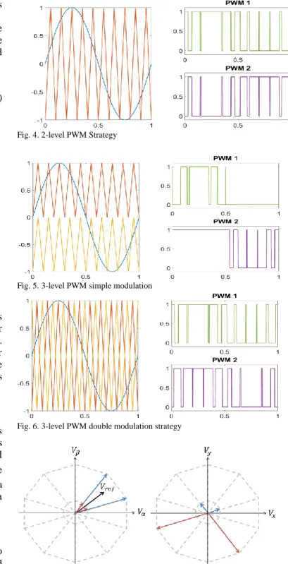
A. Two-level PWM strategy
The principle of this strategy is given in Fig. 4. It consists in giving inversed PWM signals to two inverter legs supplying the same phase. In this case, the phase voltages will be either VDC or VDC, reducing to 32 (2 ) the possible 5 voltage reference vectors. Using the Concordia Transformation, it is possible to see that all 32 vectors have a non-null projection on the homopolar frame .
B. Three-level PWM simple modulation strategy
In comparison to the 2-level strategy, this one uses two triangle carrier signals, one for the positive voltage values and another to the negative values (Fig. 5). It reduces by almost half the number of commutations, which also generate losses in the inverter, but this aspect is not analyzed in this paper. Furthermore, all 243 vectors are used in this modulation strategy. The advantage of this strategy is the fact of using voltage vectors which the homopolar voltage is low or even null and also vectors which value is closer to the referencevoltage vectors one. For example, if the reference vector is [0.1 -0.5 0.9 -0.7 0.3] VDC , a combination of the vectors as [0 -1 1 -1 0]VDC and others can be used in order to obtained reference voltages.
Fig. 4. 2-level PWM Strategy
Fig. 5. 3-level PWM simple modulation
Fig. 6. 3-level PWM double modulation strategy
Fig. 7. Z-SVPWM Strategy. Chosen four vectors projection in α-β and x-y frames.
C. Three-level PWM double modulation strategy
This strategy is similar to the previous one. There are also two triangle carrier signals, the first one is the same of the 2-level PWM and the second is its mirror (Fig. 6). As the 3-level PWM simple modulation strategy, all 243 vectors are used. But, there are as many commutations as the 2-level PWM strategy.
D. Eight-vector Z-SVPWM strategy
The 8-vector Z-SVPWM strategy (Fig. 7) is the most complex one since it involves only some specific vector of the possible 243 ones to supply the machine. Many criterions can be used to select the vectors that will be implemented. In this study, as the homopolar current is the main issue, the select vectors are the ones which the homopolar projection is null. 51 vectors correspond to this criterion. By only using these vectors, the homopolar current is theorically null.
Analyzing the select vectors in the α-β frame, it is possible to see that 10 vectors (Vl) have the highest amplitude (1,94
DC
V ), allowing to supply the phases with a higher voltage. However, those 10 vectors have a non-null projection on x-y frame. This might generate a torque ripples, because the third harmonic of the Back-EMF is not null. That is why 10 other vectors (Vs) will be also used in order to compensate the voltage projection on x-y frame.
Being chosen the 20 vectors that will be used to supply the machine, the modulation strategy will work as follows: with the voltage reference projection on the main subspaces the four closest vectors will be used to generate reference vector projection. Then every vector will have its own activation duration (Tl1, Tl2, Ts1and Ts2) respecting the equation (2):
5 2 2 1 1 j s s s l l s s s l l j ref e T V T V T T V T V T e V (2)
In order to compensate the projection of the vectors on x-y frame, the relation of the equation (3) must be respected.
22 . 4 2 2 1 1 s l s l s l V V T T T T (3) This is made for the four vectors that will generate the voltage reference on the α-β frame. With the same principle, four other vectors will be chosen to generate the voltage reference on the x-y frame, totalizing thus eight vectors as indicated in the strategy name.
For every commutation period the activation durations of all eight vectors must be recalculated.
V. CO-SIMULATION RESULTS AND COMPARISON This section presents a summary of the main simulation results conducted on the finite elements (FE) co-simulation software presented in Fig. 1. The co-simulation software has been set up by using Matlab/SimuLink. Regardless the used modulation technique, the motor-inverter set has been modeled with a toolbox model of the power switches and of the by-pass diodes with data from the supplier. A dead time of 1 µs has been introduced to prevent
supplier. All tests have been carried out in permanent operating conditions.
The obtained motor phase currents derived from Matlab/SimuLink have been then used to fed a FE model (ANSYS Maxwell 2D) of the five-phase machine, generating thus the losses density map of the machine. The parameters of the five-phase PMSM are given in Table. I.
A. Machine control simulation
Simulations are carried out for every modulation strategy for a 1000 rpm as rotation speed. The delivered torque is 20 N.m and the resulting power is 2.1 kW . The fundemental frequency is of 116 Hz and the third harmonic of 350 Hz. The results are depicted on Fig. 8 to Fig. 13. As annouced above, the aim of this work is to apply a modulation technique for the five-phase PMSM giving the same harmonic components as those obtained for a star-connected PMSM, as depicted in Fig. 8.
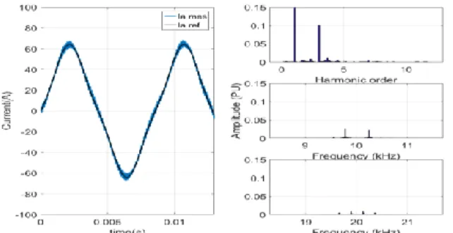
Considering open-end windings configuration, for each modulation strategy, high frequency components (at switching frequency) are visible on the motor phase currents but the highest values are obtained for a 2-level PWM strategy, as illustrated in Fig. 9. These results are in accordance with previous addressed works in this subject. In fact, the harmonic content of the current presents high frequency components at the switching frequency (10kHz) with an amplitude of 14% compared to the fondamental current amplitude.
Regarding the two 3-level strategies (simple or double modulation), the double modulation has the lowest high-frequency components. Moreover, the double modulation induces high-frequency components at the double of the PWM switching frequency.
Even if the Z-SVPWM has theorically the best performance regarding high frequency homopolar components supression, it is not what is obtained in simulation with an almost perfect VSI. This happens mostly because of the low activation duration of the vectors controlling the current in the x-y frame and the transistors dead-time. As a consequence, some low-frequency harmonics appear.
By analyzing the time-domain waveforms of the homopolar currents (see Fig. 13) for each modulation strategy, the observations above are confirmed. The 2-level PWM strategy is the one presenting the highest value of the homoplar current compoenent at switching frequency. However, the next analysis will verify if the two 3-level PWM strategies are already effective enough on heat dissipation reduction. It should be highlighed that the temperatures experimentaly obtained in the different windings with both 3-level PWM strategies are of the same order as the ones obtained with a star connection topology.
Fig. 8. Obtained current of phase A and its reference, with the current harmonics spectrum for star-connected 5-phase PMSM.
Fig. 9. Obtained current of phase A and its reference, with the current harmonics spectrum for 2-level PWM.
Fig. 10. Obtained current of phase A and its reference, with the current harmonics spectrum for 3-level simple modulation.
Fig. 11. Obtained current of phase A and its reference, with the current harmonics spectrum for 3-level double modulation.
Fig. 12. Obtained current of phase A and its reference, with the current harmonics spectrum for 8-vector Z-SVPWM.
Fig. 13. Homopolar current obtained for each modulation strategy.
B. Finite Model co-simulation
The obtained currents from simulation stage are introduced to the FE model using ANSYS Maxwell software.
As the low-frequency harmonic components have really low impact on skin and proximity effects [13]-[15] in the motor phase windings, their RMS values are used instead. The FE simulation is achieved over two PWM periods. The obtained results regarding the copper losses cartographies are illustrated on Fig. 14 to Fig. 19. The average copper losses in all windings of the five-phase PMSM are depicted in Table. II.
From the obtained results, as expected, the high frequency homopolar current components result in a copper losses increase of almost 50%in the case of the 2-level PWM strategy applied in comparison to the star-connected PMSM considered as a reference basis. The two other strategies (3-level simple modulation PWM and Z-SVPWM) have similar behavior concerning the copper losses, which are about 27 % higher than those obtained with the star-connected PMSM, as summarized in Table. II. On the contrary, copper losses obtained for the 3-level
double modulation PWM is similar to the ones obtained with the star connected five-phase PMSM.
Regarding the efficiency, the 3-level simple modulation PWM and the Z-SVPWM have the same efficiency (96.7%) since they have the same level of copper losses as observed in Table II. The 3-level double modulation has the higher efficiency (97.2%) since the copper losses are the lowest. On the contrary, the 2-level PWM strategy has the worst efficiency (96%) among the studied strategies, since the significant level of losses in windings.
Beyond this, there are other particular effects that must be taken into account for analysis like as the skin and proximity effects. As expected by the FE model, the results illustrated in Fig. 14 to Fig. 18 allow the visualization of high copper losses (almost 6 times more) located at the coils conductors close to the rotor. Consequently, this can result in hotspots formation in such conductors. In Fig. 19, the normalized copper losses in some rotor-side conductors in the coils are given for the four PWM strategies. It is observed that are the most impacted by the proximity effect and have the majority of contribution in the overall copper losses.
Fig. 14. Copper losses cartography for the star-connected configuration.
Fig. 15. Copper losses cartography for 2-level PWM strategy.
Fig. 16. Copper losses cartography for 3-level simple modulation PWM strategy.
In future works, the thermal behavior of the five-phase PMSM for each strategy will be investigated, in order to prove the variability of the given conclusions here.
VI. CONCLUSION
If open-end windings machines are attractive for integrated drives, it appears that important losses due to high frequency homopolar current components can be induced. In this paper,
Fig. 17. Copper losses cartography for 3-level double modulation PWM strategy.
Fig. 18. Copper losses cartography for Z-SVPWM strategy.
Conductor number
Fig. 19. Comparison of the copper losses in coil conductors at the rotor-side of motor phase windings for four modulation strategy.
different modulation strategies are compared in order to reduce the copper losses. The 2-level PWM strategy is the one presenting the highest dissipation among all strategies. In order to simplify the modulation, this strategy reduces the number of voltage vectors supplying the machine without taking into account the homopolar current generation. The
TABLE. II
AVERAGE COPPER LOSSS PER TOPOLOGY AND PER MODULATION STRATEGY FOR THE FIVE-PHASE PMSM
Topology Modulation Strategy Total copper losses (PU) Motor efficiency(%) Star-connected 1.0 97.2 Open-end winding 2-level PWM ≈1.5 96 3-level PWM simple modulation ≈1.27 96.7 3-level PWM double modulation ≈1.0 97.2 8-vector Z-SVPWM ≈1.27 96.7
other three strategies present similar results with copper losses very similar to the ones obtained for a star-connected machine. The lowest homopolar current is obtained when the 3-level PWM with double modulation is applied. The double modulation generates harmonics on a frequency that is the double of the commutation frequency of each transistor. Even though the Z-SVPWM strategy theoretically eliminates the homopolar current, in practice this strategy is very sensitive to effects as the transistor’s dead-time, for example. Consequently, low and high frequency harmonics might appear increasing then the copper loss
VII. ACKNOWLEDGMENT
This work has been achieved within the framework of CE2I project. CE2I is co-financed by European Union with the financial support of European Regional Development Fund (ERDF), French State and the French Region of Hauts-de-France.
VIII. REFERENCES
[1] Y. Burkhardt, A. Spagnolo, P. Lucas, M. Zavesky, and P. Brockerhoff, “ Design and analysis of a highly integrated 9-phase drivetrain for EV applications ”, IEEE International Conference on Electrical Machines (ICEM’2014), Berlin, Germany, 2014, p. 450-456.
[2] S. M. Lambert, B. C. Mecrow, R. Abebe, G. Vakil, and C. M. Johnson, “Integrated Drives for Transport - A Review of the Enabling Thermal Management Technology ”,Vehicle Power and Propulsion Conf. (VPPC’15), Montreal, QC, Canada, 2015, p. 1-6.
[3] M. El-Refaie, “Integrated electrical machines and drives: An overview ”, IEEE InternationalElectrical Machines & Drives conf. (IEMDC’2015), Coeur d’Alene, ID, USA, 2015, p. 350-356.
[4] J. Wang, Y. Li, and Y. Han, “Integrated Modular Motor Drive Design With GaN Power FETs ”, IEEE Trans. Industry Applications, vol. 51, no 4, p. 3198-3207, juill. 2015.
[5] R. Abebe and al., “Integrated motor drives: state of the art and future trends ”, in IET Electric Power Applications, vol. 10, no 8, p. 757 771, sept. 2016
[6] T. M. Jahns and H. Dai, “The Past, Present, and Future of Power Electronics Integration Technology in Motor Drives ”, CPSS Transactions on Power Electronics and Applications, vol. 2, no 3, p. 197-216, sept. 2017.
[7] A. Morya, M. Moosavi, M. C. Gardner, and H. A. Toliyat, “Applications of Wide Bandgap (WBG) devices in AC electric drives: A technology status review ”, International Electric Machines and Drives Conf. (IEMDC’2017), Miami, FL, USA, 2017, p. 1-8. [8] F. Barrero and M. J. Duran, “ Recent Advances in the Design,
Modeling, and Control of Multiphase Machines. Part I ”, IEEE Trans. on Industrial Electronics, vol. 63, no 1, p. 449-458, janv. 2016.
[9] A. Rosen, M. Groninger, and A. Mertens, “ Modeling and optimized control of fault-tolerant H-bridge fed multiphase drives ”, 17th
European Conference on Power electronics and Applications (EPE’15 ECCE-Europe), 2015, p. 1-6.
[10] N. Bodo, M. Jones, and E. Levi, “ A Space Vector PWM With Common-Mode Voltage Elimination for Open-End Winding Five-Phase Drives With a Single DC Supply ”, IEEE Trans. Industrial Electronics, vol. 61, no 5, p. 2197-2207, mai 2014.
[11] H. Zhan, Z. Zhu, and M. Odavic, “Analysis and Suppression of Zero Sequence Circulating Current in Open Winding PMSM Drives With Common DC Bus ”, IEEE Trans. on Industry Applications, vol. 53, no 4, p. 3609-3620, juill. 2017.
[12] X. Kestelyn, and E. Semail, “A vectorial approach for generation of optimal current references for multiphase permanent-magnet synchronous machines in real time,ˮ IEEE Trans. Ind. Electron., vol. 58, no. 11, pp. 5057-5065, Nov. 2011.
[13] A. Młot, M. Korkosz, P. Grodzki, and M. Łukaniszyn, “Analysis of the proximity and skin effects on copper loss in a stator core ,” Archives of Electrical Engineering, vol. 63, no. 2, pp. 211–225, 2014.
[14] S. Iwasaki, R. P. Deodhar, L. Yong, A. Pride, Z. Q. Zhu, and J. J. Bremner, “Influence of PWM on the proximity loss in permanent magnet brushless AC machines,” IEEE Trans. Industrial Applications Vol. 45, no. 4, pp. 1359-1367, 2009.
[15] A. S. Thomas, Z. Q. Zhu and G. W. Jewell, “Proximity loss study in high speed flux – switching permanent magnet machine,” IEEE Trans. Magnetics, Vol. 45, no. 10, pp. 4748-4751, 2009.
Tiago José Dos Santos Moraes received the B.Sc. degree in Electrical
Engineering from Institut National de Sciences Appliquées (INSA Lyon), Lyon, France, in 2011 and from the Universidade Federal do Rio de Janeiro (UFRJ), Rio de Janeiro, Brazil, in 2012 and the M.Sc. degree in Electrical Vehicles from the Arts et Métiers ParisTech, Lille, France, in 2013. In 2017, he received his PhD degree from Arts et Métiers ParisTech. His researches include fault-tolerant series-connected multiphase machines for aeronautics and aerospace industries.
Mohamed Trabelsi (M’16) received the B.S. and M.S. degrees from the
École Supérieure des Sciences et Techniques de Tunis, University of Tunis, Tunisia and the Ph.D. degree jointly from the Aix-Marseille University, Marseille, France, and the École Supérieure des Sciences et Techniques de Tunis, University of Tunis, all in electrical engineering. He is a doctor research engineering position with the Laboratory of Electrical Engineering and Power Electronics of Lille, Arts et Metiers ParisTech, Lille, France. He is also an Associate Professor of Electrical Engineering with the École Nationale d’Ingénieurs de Sousse, Sousse, Tunisia. His current research interests include modeling, control, and diagnostics of conventional threephase ac motor drives, power converters, and multiphase drives.
Hussein Zahr (SM’13) received the B.S. and M.S. degrees from the Faculty
of engineering, Lebanese university and Ecole Polytechnique de Nantes, University de Nantes, and the Ph.D. degree from the École Nationale Supérieure des Arts et Metiers in 2016. He is currently postdoctoral researcher in electrical engineering at Ecole Nationale Superieure des Arts et Metiers, Lille, France. His current research interest includes design, modeling, and control of multiphase machines.
Eric Semail (M’02) received the graduate degree from Ecole Normale
Superieure, Paris, France, in ´ 1986. He received the Ph.D. degree in tools and studying method of polyphase electrical systems, generalization of the space vector theory, in 2000. He became an Associate Professor at the Engineering School of Arts et Metiers Paristech in 2001 and a Full Professor in 2010 in the Laboratory of Electrical Engineering of Lille (L2EP), France. His fields of interest include design, modeling, and control of multiphase electrical drives (converters and ac drives). More generally, he studies, as a Member of the Control team of L2EP, Multimachine and Multiconverter systems. Fault Tolerance for electromechanical conversion at variable speed is one of the applications of the research with industrial partners in fields such as automotive, marine, and aerospace. Since 2000, he has collaborated on the publication of 27 scientific journals, 64 International Congresses, five patents, and two book chapters.