HAL Id: hal-01851438
https://hal.archives-ouvertes.fr/hal-01851438
Submitted on 11 Jan 2019
HAL is a multi-disciplinary open access
archive for the deposit and dissemination of
sci-entific research documents, whether they are
pub-lished or not. The documents may come from
teaching and research institutions in France or
abroad, or from public or private research centers.
L’archive ouverte pluridisciplinaire HAL, est
destinée au dépôt et à la diffusion de documents
scientifiques de niveau recherche, publiés ou non,
émanant des établissements d’enseignement et de
recherche français ou étrangers, des laboratoires
publics ou privés.
Influence of design and process parameters on service
life of nut hot forging die
Véronique Garat, Gérard Bernhart, Laurence Hervy
To cite this version:
Véronique Garat, Gérard Bernhart, Laurence Hervy. Influence of design and process parameters on
service life of nut hot forging die. Journal of Materials Processing Technology, Elsevier, 2004, 147 (3),
p.359-369. �10.1016/j.jmatprotec.2003.01.002�. �hal-01851438�
Influence of design and process parameters on service life of
nut hot forging die
Véronique Garat
a, Gérard Bernhart
a,∗, Laurence Hervy
baEcole des Mines d’Albi-Carmaux, Research Center on Tools, Materials and Processes (CROMeP), 81013 Albi CT Cedex 09, France bLISI Aerospace, BP 298, 12200 Villefranche de Rouergue, France
Abstract
A nut hot forging die was investigated in order to increase its life time. In a first step forging process simulation shows that die surface temperature reaches 450 ◦C and that mechanical loads on the die are closely related to the accuracy of the initial billet length. In a second
step die thermo-mechanical simulation was used to optimize the design: geometrical aspect as well as shrink fitting were investigated. Life time increase was estimated in using the Manson universal slope relation. This increase was confirmed from the practical results.
Keywords: Nut hot forging; Die design; Numerical simulation; Shrink fitting
1. Introduction
An aircraft like the airbus A340 is made up of 4 million parts, 2 million of which are fasteners. At the beginning of fastener production, the hot forging step gives the general shape to the product and the hexagonal head is net shape forged. An important aim of the suppliers, nowadays, is to reduce the general costs of their products. The reduction of the costs of the tooling or an increase of their service life contributes to this goal.
Tool scrapping can be attributed to two major causes: the first one is due to wear and loss of accurate dimensions, the second one is rupture after crack propagation. A lot of work has been carried out on this subject for cold forming [1], hot forging[2,3]and the contribution of FEM simulation is clearly demonstrated. Nevertheless, each industrial case is different and requires a specific study.
In this paper, the brittle failure phenomenon of tools is addressed and the influence of process parameters like billet length, billet initial temperature or tool design (radius cor-ner value and shrink fit) are studied. After a description of the industrial tool working conditions, numerical simulation is used to quantify the stress distribution in the tools. The service lives of different designs were estimated using the
∗Corresponding author. Tel.:+33-5-63-49-30-56;
fax:+33-5-63-49-30-99.
E-mail address: [email protected] (G. Bernhart).
universal slope method and some design changes are rec-ommended.
2. Hot forging tool: presentation of the industrial problem
In general materials for aeronautical fastener production are very difficult to forge. To withstand the high loads without deformation, high speed steels (HSS) are usually selected. Such materials show low ductility, even at high temperature. This study concerns a hexagonal nut die which shows a very limited service life (often less than 100 pieces are forged before complete failure). While all parameters related to the forging press are closely controlled, other causes such as design, shrink fit influence, temperature or small variations of billet length are assessed.
2.1. Tools and materials for hexagonal nut hot forging
The high hardness (61–62 HRc) high speed steel (HS-6-5-2, AISI M2) forging die, described in Fig. 1, is shrink fitted before use in an AISI H11 ring with a 200 MPa loading. The cylindrical billets (13 mm long and 7.3 mm in diameter) are in stainless steel X6 NiCrTiMoV 25. They are lubricated with MoS2powder, then heated by induction
to 1100◦C and forged with a 25 t press. The forging takes less than 0.1 s but the time between the strike and the nut ejection is about 8 s, which allows the shrinking of the steel and limits die wear.
Fig. 1. Dimensions of the hexagonal die.
2.2. Die failure
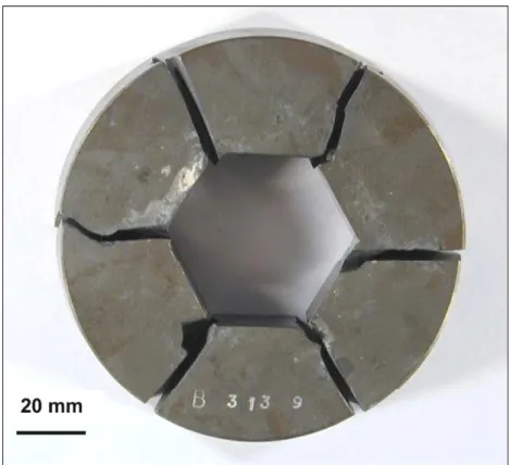
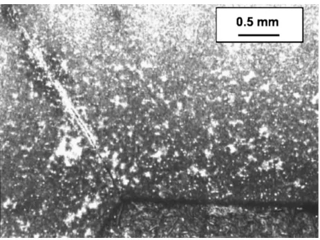
After less than 100 forging cycles, cracks appear in the die corners and reach the external part of the tool a few strikes later, as shown inFigs. 2 and 3. Die failure may be attributed to one of the four following factors[4]:
1. tool steel selection and quality; 2. die design and manufacturing; 3. heat and surface treatments; 4. forging process parameters.
As points 1 and 3 are supposed to follow the basic rules of the forging industry, this study is focused on the ence of die design and process parameters. To avoid influ-ence of the brittle and heat affected layers due to electro discharge machining (which is known to reduce fatigue life
Fig. 2. Typical failure of an hexagonal die at corners.
[5,6]), conventional machining was chosen to manufacture the die.
Amongst the possible mechanisms listed by Bobke and Luig[7], i.e. wear, plastic strain, thermal cracking and me-chanical cracking, nut forging die rupture is clearly a result of the last one. As a consequence, major effort is placed on the understanding and the explanation of this rupture mechanism in relation to die design and forging process parameters.
2.3. Design of hexagonal nuts and screws: norms analysis
Usually, customer specifications give no requirements on the radii in the corners of hexagonal as forged screws and nuts. According to international norms ISO 4759 I and II
[8]regarding tolerances on the dimensions of such products, the maximum value allowed for the radius corner can be defined as (Fig. 4):
Rc=
fmax−√3/2cmax
2−√3 (1)
where Rc is the radius corner value, fmax and cmax are the
across flat and the across corner dimensions.
Related to the nut geometry, a maximum radius value of 0.6 mm is allowed. Taking into account a possible non-uniform filling of the die during the forging and a change of dimension due to wear, a maximum allowable radius of 0.5 mm is considered.
Fig. 3. Failure initiation located in corners.
3. Numerical simulation of nut hot forging 3.1. Presentation of the parametrical study
The methodological approach followed in this study is shown inFig. 5. It involves three different steps:
1. the first step consists in the axisymmetric simulation of the forging operation using the FE software Forge2®. Two combinations of parameters are studied:
• the initial length of the billet, which is cut from bars and may vary in a range of±1.5%;
• the initial billet temperature, which is nominally 1100◦C but can be less (as low as to 1000◦C) due to the time required for the billet transfer from the inductor to the die;
2. the second step aims to study the influence of the radius corner value and the shrink fit pre-loading on the stress and strain levels. The non-axisymmetric isothermal sim-ulation is performed using I-DEAS®finite element soft-ware;
3. in the third step, the two previous simulations are linked, so that the radial stresses calculated under Forge2® are
applied to the different die designs. Results allow an es-timation of the service life, thanks to the universal slope method.
Fig. 4. Hexagonal screw, dimensions and radius.
Finally, the optimum parameters (especially, the radius corner value) are tested on the process line to validate the theoretical results.
3.2. Numerical simulation of forging process parameters variations
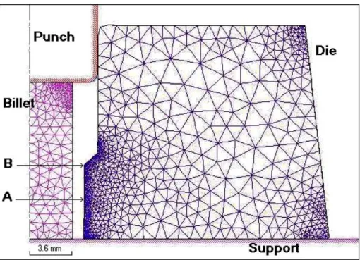
To reduce the computational costs and time, the simula-tion assumes an axisymmetric die and nut.Fig. 6shows the evolutive six-node finite element meshing. In order to ob-tain accurate stress distribution, a refined meshing is used at the inner surface of the die to include the rapid temperature change.
The billet is thermo-viscoplastic, the die is thermo-elastic, the punch and the plate support are assumed to be rigid
Fig. 6. Mesh of die and billet (Forge2®).
Table 1
Physical and mechanical properties of HSS M2 steel[7,8]
E0 (GPa) R0.2 (MPa) ν0 a0 (◦C−1) Cp(J/kg K) ρ(kg/cm3) λ(W/m K) α(10−6K−1)
20◦C 211 2155 0.31 0.378 439 8.15 20 11.3
450◦C 180 1700
bodies. The stress levels along the vertical location of the die are monitored and two points A and B (Fig. 6) are closely observed. Point B corresponds to the transition between the hexagonal head and the flange of the nut (see alsoFig. 8).
3.2.1. Thermal mechanical behavior
The linear temperature-dependent behavior of the die is described as follows:
E= E0(1+ a0T), ν= ν0(1+ a0T) (2)
with E0the young modulus at T = 20◦C and ν0Poisson’s
ratio at T = 20◦C.Table 1 [9,10]summarizes the mechan-ical data.
Billet behavior is described with a Norton–Hoff law, given byEq. (3): σ= K1¯εn ˙¯εmexp ! β T " (3) where K1 is the consistency, m the strain rate exponent, ¯ε
the effective strain, ˙¯ε the effective strain rate and n is the hardening coefficient.
Table 2
Physical and mechanical properties of X6 CrNiTiMoV 25 billet material[9]
K0(MPa) n m β(K) E (GPa) ν ρ(kg/m3) Cp(J/kg K) λ(W/m K) a (×106mm/mm◦C)
297 0.019 0.126 7325 483 0.35 7.3 483 35 23.2
By introducing the stress deviator (Eq. (4)), the constitu-tive equation used in Forge2®can be derived (Eq. (5)): ¯¯s = 2K#√ 3˙¯ε$m−1¯¯¯ε˙ (4) K= K0(¯ε + ¯ε0)nexp ! β T " (5) with K0= K1/ #√ 3$m+1and ˙¯ε = % # 2/√3$¯¯¯ε˙:¯¯¯ε˙
The values of these parameters for the X6 NiCrTiMoV 25 are presented inTable 2 [9].
The contact between the billet and all the tools (rigid and thermo-elastic) is modeled with a Coulomb law limited by Tresca (Eq. (6)): ∥τ∥ = µσn if µσn< ¯m σ0 √ 3, ∥τ∥ = ¯m√σ0 3 if µσn≥ ¯m σ0 √ 3 (6)
Fig. 7. Die boundary conditions for I-DEAS®numerical simulation.
where σn is the normal stress, τ the friction shear stress, σ0
the flow stress, µ the Coulomb friction coefficient and ¯m is the shear friction factor.
The values of ¯m = 0.2, µ = 0.4 were chosen according to previous work[2].
3.2.2. Thermal boundary conditions
Two initial uniform billet temperatures are studied: 1100◦C nominal temperature and 1000◦C. The thermal properties of the billet materials are presented in Table 2 [9]. The thermal exchange coefficient between tools and billet is fixed at 20000 W/m2K[2].
3.3. Numerical simulation of die design
Isothermal numerical simulation is performed under I-DEAS®finite elements software. Taking into account the symmetries of the hexagonal nut, only 1/4 of the cross sec-tion of the die is considered (Fig. 7). A thin shell six-node element meshing is used. Non-linear elasto-plastic behav-ior of the high speed steel material is introduced using a piecewise linear model.
Fig. 8. Temperature in the nut and in the die (scale in mm, temperature in◦C).
A linear loading or the load increase resulting from Forge2® simulation is applied to the inner part of the die. To evaluate the influence of the radius corner, five models are considered, differing only by the radius corner value (0.05; 0.1; 0.2; 0.5; 0.7 mm). The same boundary conditions are applied. The radius values have been selected to be the closest to those found in industry: 0.05 mm corresponds to the minimum possible machining conditions and 0.5 mm is the maximum radius allowed by norms and discussed in
Section 2.3. To have a look beyond this range, a 0.7 mm radius is also studied.
To simulate the shrink fitted die, a steady even load is applied on the outer part and three levels are calculated: no shrink fit, 100 and 200 MPa.
4. Results
4.1. Axisymetric forging simulation (Forge2®) 4.1.1. Temperature and stress distribution in the die
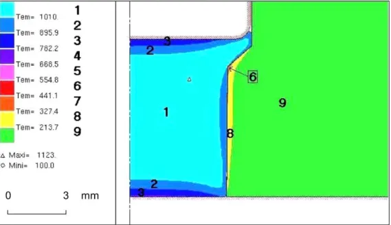
Fig. 8shows the temperature gradients in the billet and die, just after the strike of the punch. Very important thermal gradients are noticed on the die surface and the highest tem-perature (450◦C) is located at the die transition point (point 6) which corresponds to point B inFig. 6. The temperature in the body of the die remains close to room temperature during the whole forging operation.
Fig. 9shows the radial (a) and circumferential (b) stress distribution at the end of the strike. Maximum stresses are located at the mid-high of the nut (point A ofFig. 6), whereas the transition point (point B) is less constrained. The radial stresses in the die are compressive and their values decrease quickly from the inner side to the center of the die. The stress singularity noticed at the bottom of the die (in contact with
Fig. 9. (a) Radial stress σrr in the die (MPa); (b) circumferential stress σt in the die (MPa).
the lower rigid support (b)) may be related to the no-slip contact condition.
4.1.2. Forging load evolution overtime
The load evolution during one forging step is plotted in Fig. 10 for the three billet process parameters studied (see Section 3.1). Compared to nominal conditions (stan-dard length 13 mm, temperature 1100◦C), a drop of 100◦C of the initial billet temperature introduces only a limited in-crease of the load (+12%). In contrary the 1.5% increase of the initial length induces a dramatic increase of the forging load (+60%) and gives evidence of the necessity of a close control of this process parameter.
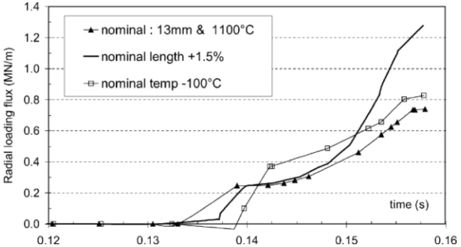
The evolution of radial loading flux is plotted inFig. 11
for point location A. It is defined as the load for a unit length (in MN/m) and corresponds to the radial stress at the inner surface of the die. It will be used later as load condition for I-DEAS®combined load simulation.
4.2. Non-axisymetric simulation of die design influence
A linear load increase is applied to the different radius corner models (see Fig. 7), to point out the importance of
Fig. 10. Forging load evolution in the punch for different billets param-eters.
Fig. 11. Radial loading evolution in the die during the forging for different billets parameters (point A).
the radius corner values and the pre-load applied by the shrink-fitting. All simulations are performed at room tem-perature as the maximum temtem-perature at point A (where the maximum load is applied) reaches only 200◦C and as the HSS M2 steel exhibits low property changes at this temper-ature.
4.2.1. Radius corner value influence
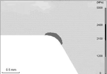
As expected, the radius influence is clearly demonstrated, and is shown inFigs. 12 and 13where the Von Mises plastic equivalent stress is plotted for two radii (0.05 and 0.5 mm) under the same radial loading flux (500 kN/m). In the die with a 0.05 mm radius, the plastic zone looks like a crack front with the formation of two ‘ears’ corresponding to a typical configuration of a high stress concentration zone. It may lead to a crack initiation during the first strike and, as the steel has a low toughness, to a rapid propagation dur-ing the next hits. In the 0.5 mm radius die, the strain is well distributed along the radius; there is a smooth stress
con-Fig. 12. Von Mises equivalent stress in die with a 0.05 mm radius. Radial load: 500 kN/m.
centration. The stress level is significantly reduced, −30% in this particular loading case.
Taking into account the simulated radius values of 0.1, 0.2 and 0.7 mm, Fig. 14 shows the evolution of the Von Mises equivalent stress as the level of the radial loading flux increases. The non-linearity of these curves is related to the non-linear elasto-plastic behavior of the material. The stress decreases while the radius increases, up to a limit value of 0.5 mm, over which the radius seems to have less influence. On this plot are also reported the yield stress and rupture stress of the die material at 20◦C. It can be seen that these stresses are largely over-crossed in the die.
4.2.2. Shrink fit influence
Fig. 15shows the effects of the application of a shrink fit pre-load on the outer part of the die (corner radius 0.5 mm). The stress increases with the forging load, but, if a shrink fit is applied, the equivalent Von Mises stress first decreases. Indeed, the tensile stresses first compensate the compressive
Fig. 13. Von Mises equivalent stress in die with a 0.5 mm radius. Radial load: 500 kN/m.
Fig. 14. Evolution of Von Mises stress with radial loading for different die radii.
Fig. 16. Evolution of Von Mises plastic strain during the forging for different radii.
ones introduced by the shrink fitting; this effect is equivalent to delay the loading and so the entrance into the plastic zone of the material. Below the yield strength, the shrink fitted curves have the same slopes, beyond this value, the influence of shrinking is not as important as die material undergoes important plastic straining. In the elastic zone, the up to 600 MPa stress difference between 200 and 0 MPa shrink fit level shows the great importance of the selection and the control of this parameter.
4.3. Combined simulation
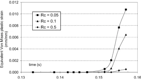
In the combined simulation, the radial loading flux his-tory ofFig. 11(for the nominal conditions 13 mm length and 1100◦C) is applied to a 200 MPa shrink fitted die.Fig. 16
shows the evolution of the equivalent Von Mises plastic strain versus time for three different radii: 0.05, 0.1 and 0.5 mm. For the highest level of the radius, plastic strain is small and remains under the conventional limit of elasticity (corresponding to a 2× 10⁻³plastic strain). Knowing that
the maximum plastic strain in tensile rupture testing of the die material at 450◦C is close to 1.2×10⁻²[10], 0.1 mm and
especially 0.05 mm radius values may produce rapid crack initiation during the first nut production. Moreover, when radius value is low, a little variation (0.05–0.1) introduces an important modification of the plastic strain.
5. Discussion and service life 5.1. Discussion
All these results show the influences of combined design and process factors. One of the most important seems to be the radius in the hexagonal head of the nut. The use of a 0.5 mm radius seems to be the best compromise between the norms specifications and the stress distribution in the die. As a matter of fact, it allows to stay under the conventional
yield strength, whereas for lower radii, the ultimate strength would be overcome. The use of high hardness steels (and in consequence low toughness steels) to form the high me-chanical property billets promotes the crack propagation af-ter initiation on the inner part of the die.
Another important design factor is shrink fit. It enables to reduce the equivalent Von Mises stress in the tools and to delay the failure initiation. Nevertheless, its efficiency is restricted to the elastic domain and seems to vanish when the die undergoes important plastic straining.
At least, this study shows also the influence of the billet initial length, for which an increase of 1.5% (corresponding to the general accuracy of the cutting machine) multiplies the mechanical loads on the die by a factor of 2.
5.2. Service life prediction
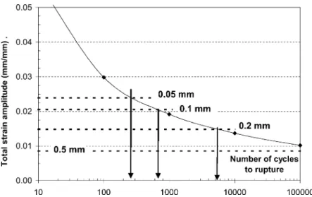
An estimate of the impact of these finite element calcula-tions on fatigue life may be performed using the universal slope method proposed by Manson[11]. This method allows to link service life and total strain amplitude, whatever the material under consideration. The advantages of the method are the limited number of material properties needed and the fact they can be defined thanks to a simple tensile test. He derives the relation below:
)εtotal= M(Nf)Z+
G E(Nf)
γ (7)
where Nf is the number of cycles to failure, E the elastic
modulus of the material, Z and γ are constant parameters (respectively, −0.6 and −0.12) and M and G are defined by the equations: M = −ln(1 − Ra)0.6, Ra is the reduction
in area; G= 3.5σu, σu is the ultimate tensile strength; E,
Ra and σufor the HSS M2 steel are, respectively, 210 GPa,
0.024 and 2400 MPa.
Fig. 17andTable 3report an estimate of the service lives, for different radius corner values. For the lower radius corner value, the service life is very low, 260 cycles. For 0.2 mm, the number of cycles to failure increases to 5200 cycles; it
Fig. 17. Universal slope diagram for HSS M2 steel and life time of dies with respect to corner radius.
reaches more than 105 cycles for 0.5 mm. This evaluation does not take into account the problems like wear and all the other possible causes of failure, but it gives a good way to compare and to quantify the radius corner influence.
5.3. Industrial verification
Verification of simulation results are performed on dies with the 0.3 and 0.5 mm radius. The nominal die life in the 0.05 mm radius configuration is between 50 and 200 pieces. These data are coherent with the theoretical evaluation of service life done in the previous paragraph. Following ob-servations have been performed with the new die designs.
First, the introduction of design with 0.3 and 0.5 mm ra-dius induces no extra costs during the machining. Second, the nuts have good dimensions according to the specifica-tions and norms, and even better: as a matter of fact, nuts with a low radius are sensitive to thermal cracking during quenching, due to the high stress concentration induced by high temperature gradients in the corners. When radius is increased, these problems become less important. Observa-tion of the cross-secObserva-tion of the as forged nuts shows that the radii are 0.4 and 0.6 mm with respectively, the 0.3 and 0.5 mm dies.
Second, filling of the bottom of the dies with the old designs was often difficult and requires higher forging loads. Now there is a radius and there is no more a need to increase
Table 3
Estimated dies service life, depending on the radius corner of the die (Rc), for a 200 MPa shrink fit
Rc(mm) )εtotal (mm/mm) Service life
0.05 2.387× 10⁻² 260
0.1 2.052× 10⁻² 700
0.2 1.448× 10⁻² 5200
0.5 8.55× 10⁻³ >105
the loads to produce nuts without defects.
At least, no rupture nor crack initiation were observed during production after 1000 nuts. Tests are continuing.
6. Conclusion
Increase of nut forging die life time was investigated with a combined forging process and thermo-mechanical die sim-ulation. It was in particular shown that:
• a closer control of the initial billet length is more important than a control of billet forging temperature. A 1.5% error (i.e. 0.2 mm in this case) multiplies the forging load and the radial loading flux on the die by a factor of 2; • an increase of the corner radius of the die from 0.05 to 0.5
(which remains compatible with nut norms) may increase the life time by a factor greater than 100;
• a well controlled shrink fitting of the die has a major effect on stress level. This effect vanishes nevertheless, when high plastic strains are reached, i.e. when die design is not optimized.
Modification of the die design have been introduced in industry and results show a significant increase in die life time as expected.
Acknowledgements
The authors would like to acknowledge the company LISI Aerospace for its financial and technical support to this study.
References
[1] J. Walters, S. Kurtz, W.-T. Wu, J. Tang, The ‘state of the art’ in cold forging simulation, J. Mater. Process. Technol. 71 (1997) 64–70.
[2] O. Brucelle, G. Bernhart, Methodology for service life increase of hot forging tools, J. Mater. Process. Technol. 87 (1999) 237–246. [3] O. Sandberg, B. Klarenford, H. Lindow, A new hot work tool steel
with improved properties, tool steel in the next century, in: Proceed-ings of the Fifth International Conference on Tooling, University of Leoben, Austria, 29 September 1999.
[4] B. Chicco, G.L. Powell, G. Hefrfurth, E. Summerville, Failure in Hot Forging Dies, Materials Australia, September/October 1997, pp. 24–26.
[5] G. Frediksson, J. Bergström, S. Hogmark, Crack growth in cold work tool steels—influence of surface condition, microstructure and hardness, tools steels in the next century, in: Proceedings of the Fifth
International Conference on Tooling, University of Leoben, Austria, 29 September 1999.
[6] H.-J. Kim, J.F. Wallace, Effect of EDM and its mitigation by surface modification on thermal fatigue properties, Surf. Eng. 10 (1) (1994) 56–64.
[7] T. Bobke, H. Luig, Causes de Défaillances des Outils d’Estampage, University of Hanover, 1989 (translation).
[8] Norms ISO 4759, I and II. Tolerances for Fasteners, 1978. [9] Technical Data Base, Blanc LISI Aerospace.
[10] G. Bernhart, unpublished test results.
[11] S.S. Manson, Thermal Stress and Low Cycle Fatigue, McGraw-Hill, New York, 1966.