OATAO is an open access repository that collects the work of Toulouse researchers and makes it freely available over the web where possible
Any correspondence concerning this service should be sent
to the repository administrator: [email protected] This is an author’s version published in: http://oatao.univ-toulouse.fr/26693
To cite this version:
Benoist, Vincent and Arnaud, Lionel and Baili, Maher and Faye, Jean-Pierre Improved design methodology for additive manufacturing including machining load cases: application to an aeronautical workpiece. (2018) In: MUGV & Manufacturing’21, 7 June 2018 - 8 June 2018 (Bordeaux, France).
Improved Design methodology for Additive
Manufacturing including machining load
cases: Application to an aeronautical
workpiece.
Vincent BENOIST
(a) (b), Lionel ARNAUD
(a), Maher BAILI
(a),
Jean-Pierre FAYE
(a)(a) Laboratoire Génie de Production, École Nationale d’Ingénieurs de Tarbes, Université de Toulouse, INP-ENIT, Tarbes Cedex, France. Mail : [email protected],
[email protected], [email protected], [email protected]
(b) Héphaïstos-Cousso, Avenue Cassou de Herre, Nogaro, France.
Abstract: This paper focuses on the impact of post processing machining and mounting
/ unmounting phases on topological optimization methods. In addition to the classical load cases taken into account in optimization methods, various static and vibratory forces occurring during machining phases and manipulations, are also considered. Results of the topology optimization show that the most significant load case for the aeronautical part considered is indeed one of the post processing machining operations and it has a strong impact on the optimized shape. This result shows that such post processing phases have to be taken into account, whatever they represent supports removal or finishing surfaces. Supports are most of the time mandatory but their removal by machining operation may be require a non-negligible time, skill and cost. In this paper the machining operations are first studied through their effects on topological optimization. Then the cutting phenomenon is numerically modeled to explore various options of build supports and prevent the part from damages due to tearing. Finally, this paper demonstrates that cutting forces analysis should encourage designers (i.e. topology optimizers) and machinists to interact, in order to minimize the total cost of the additive manufactured workpiece
Keywords: DFAM, Topology optimization, Support, Cutting force model, Vibrations,
1 Introduction
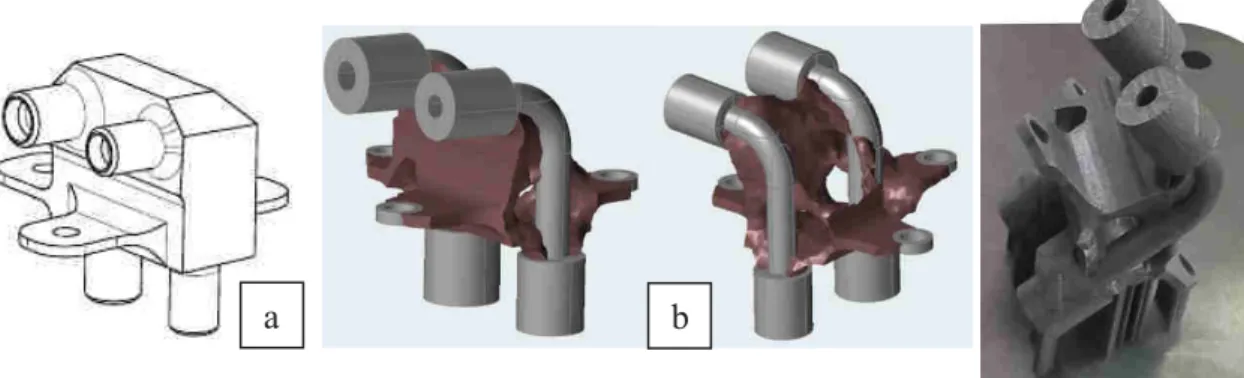
For more than 20 years additive manufacturing has been used for prototyping in research and development fields. Nowadays the aeronautic industry is able to 3D print functional parts at production scale especially using SLM (Selective Laser Melting) technologies (for melting part), but mostly exclusively for high cost parts (Barlier, 2015). Additive manufacturing allows engineers to create very innovative designs but machining post processing operations are quite always necessary, and these parts are often very difficult to machine with conventional turning and milling processes, increasing final cost. Using Design for Additive Manufacturing (DFAM) methods (Louvigny, 2015) (Hällgren, 2016), such as topological optimization, engineers should be able to design the best possible part in order to comply technical specifications and to minimize production and post-production complexity especially with low rigidity parts. The cost of additive manufactured parts is very strongly related to the size and the material used, but it is quite independent of the shape complexity. Machining may represent up to 50 % of part final cost, and sometimes simply reveals to be impossible without part redesign. Aeronautical parts redesigned by topology optimization still similar in size and weight compared to the subtractive manufacturing parts. This induces that the optimize part quotation target is similar to the subtractive manufacturing part, especially if there is a lack of information about the available space around the part, or the additional features that could be included in the part redesign. Furthermore, topology optimization in an aeronautical context has a strong goal of mass reduction which often leads to optimized parts with a lower stiffness and a more complex shape (Benoist, 2017). This low stiffness and organic shape have to be precisely monitored to prevent part damage and to avoid costs due to eventually additional supports. The supports, even those just needed for linking the part to the build plate, also bring another non-negligible constraint of post processing. The entry point of this study is the cutting forces, taken into account during the topology optimization. Beside the cutting forces, that may lead to an unacceptable flexure and poor accuracy, vibration must also be avoided during machining, because it would lead to poor surface quality and possible tool or workpiece break. To ensure that all the numerical models are consistent with reality, numerical results are compared to experimental tests. It is important, here to highlight that machining time, must be precisely taken into account for optimizing the total cost of the part. The machining time has been reduced here from 40 minutes, for the subtractive initial manufactured part) to only 6 minutes for the additive manufactured part). To obtain the best total cost for the additive manufactured part it is important to realize that machining time has to be maintained to the lowest possible level from this 6 minutes level. For example, increasing slightly machining allowance to increase stiffness during machining may imply to add a machining pass and thus to double the machining time.
Figure 1: Subtractive manufacturing (a) and additive manufacturing part (b)
2 Modeling and experimentation
2.1 Cutting forces modeling
The first step, is the definition of realistic cutting forces. In order to validate a first cutting force model, finite elements calculations from the Abaqus software have been done and results compared to literature. This first 2D model is a cuboid sample representing the part, and a rigid shape representing the cutting tool (figure 3).
The literature provides the elastic material parameter for powder bed fusion manufactured Ti6Al4V. The additive manufactured titanium has the particularity to be created at the same time as the part take shape and then to be thermally tempered. So, the material parameters are slightly different from cast titanium due to the so called hyper-quenching. The literature (Barrett, 2017) provides parameters for modelling the plastic strain during machining of 3D printed Ti6Al4V. Johnson-Cook (Johnson, 1983) parameters are given as it is the most used material model in FE machining simulations, and defines the relationship between strain, strain rate and temperature as described in (Equ.1). The material studied from (Barrett, 2017) may be slightly different from the material we used during the printing job, because of thermal treatment.
= (! + "#$) %1 + & '* %#̇ #̇$-- .1 − 0 2 − 23445 25678− 234459 5 : (1)
As said before, Johnson-Cook material model relates strain, strain rate and temperature to flow stress in a multiplicative form through the parameter A, B, n, C and m. These material parameters have been found in the literature (Barrett, 2017) and are summarized in (Table 1).
Table 1: Johnson-Cook material model parameters
A B n C m
970 MPa 756 MPa 0.21 0.047 1.05
To complete material parameters, a damage law is taken into account. The Johnson-Cook failure model defines the strain at fracture as depicted in (Equ.2) (Johnson, 1985):
#;= (<>+ <?. exp (<BC) %1 + <D'* %#̇#̇
$-- %1 + <E0
2 − 23445 25678− 234459-
(2)
Where #; is the equivalent fracture strain, C the stress triaxiality parameter and the parameters <>, … , <E are determined based on a series of experimental fractures tests that depends on variation of stress triaxiality, strain rate and temperatures. Damage parameters used come from (Zhang, 2015) but these parameters concern forged titanium. Nevertheless, we used these parameters because of the lack of information in the literature about 3D printed titanium damage law.
Table 2: Johnson-Cook failure material model parameters
<> <? <B <D <E
-0.09 0.25 -0.5 0.014 3.87
The model is then created in Abaqus, with a dynamic, explicit step on a time period of 0.04 second. This time is enough for the tool to cross the sample at 0.25 m/s speed. As shown in Figure 2 the mesh has been refined in the machined zone of the sample in order to have accurate results. In cutting modelization, chip formation induces large mesh distortions and also brings the necessity to use a separation criterion to prevent numerical problems. An Arbitrary Lagrangian Eulerian (ALE) formulation has been chosen for this simulation. It allows to integrate the advantages of Eulerian and Lagrangian representations in a single description and so reduce mesh distortions (Hashemi, 1994). Finally, we used a Coulomb friction law, G = 0.2, to model the contact zone between the tool and the chip, as used in literature (Pantalé, 2004) (Zhang, 2015).
2.2 Support modeling
The second step of this paper is to investigate the machining of the supports and especially the plastic residual strain after support removal on the part. To answer this question a numerical model, based on the previous one, is created. The model is still a two-part assembly of a sample with supports and the tool. The only change between support removing model and machining models is the sample geometry (2D to 3D).
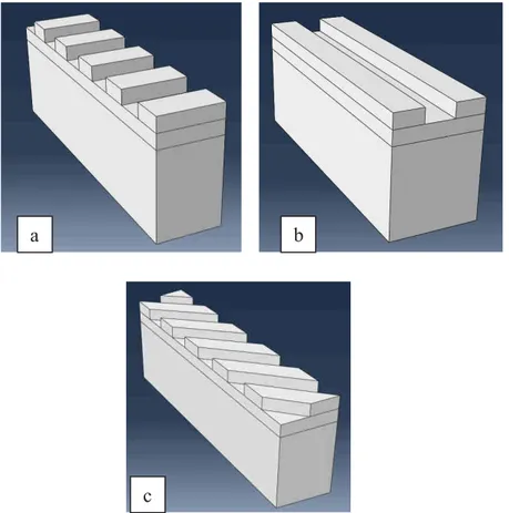
Three geometries have been created to test different supports orientation strategies 0°, 90° and 45° (figure 3). Each support has a width of 1 mm to represent classical support size. The supports are spaced apart of also 1 mm.
Figure 2: Geometry strategies 0 ° (a) up to 90 ° (b) with a 45 ° increment (c)
2.3 Built plate machining
The last investigation in this paper, is to look for the optimization of the built plate machining phase. In additive manufacturing, the built plate is considered as a consumable like the powder. After every printing job the supports have to be cleaned from the plate in order to be used again. The built plate has geometric constraints to respect in order to ensure a well quality printing for the next job. The three main constraints to respect are parallelism (0.05 mm), the flatness of the built face (0.05 mm) and the roughness (R ≈ 1.6 μm).
To process the machining phase, we used an J3 = 45° milling tool with strong inserts to surface the plate.
Aside from the geometric restrictions, our observations during built plate machining show that the built plate behavior during cutting may be very different from the printed material. For example, for 316L 3D printing, the plate material is structural steel (S355) while the printed material is stainless steel (316L). This difference is strongly affecting the cutting process because the two steels have contradictory optimal cutting parameters. The optimal cutting conditions must be able to deal with both materials to obtain high quality surface and high removal rate. The cutting conditions for this machining phases are: spindle speed of 1500 rpm and a feed rate of 0.033 mm/teeth.
a b
3 Results
3.1 Cutting forces modelling results
The first 2D numerical model concerned orthogonal cutting process. The model is constituted of 16948 linear quadrilateral elements of type CPE4R and a total number of nodes of 17202. The results, (Figure 3) with Von Mises stress field, shows a classical chip formation during tool penetration with primary shears bands and is in accord with the Oxley theory (Oxley, 1989).
Figure 3: Creation of shear stress zones
The results show that the cutting force value is always around 2000N, with a +10% maximum at 0.002 s, i.e. when the tool is just becoming to generate the chip, as illustrated (Figure 3).
3.2 Supports removal modelling results
In this section, an extension of the 2D model presented above has been realized to perform an 3D model in order to take into account the supports geometry. The number of elements and nodes in each model, are summarized in (Table 3).
Table 3: Elements and nodes number in each model for the sample
Model 0° Model 90° Model 45° Number of elements 12 400 41 200 29 698 Number of nodes 25844 67 328 46 378
For the tool, the elements and nodes description are the same for the three models. The tool is composed of 944 eight nodes thermally coupled brick explicit elements and 1269 nodes. The cutting forces results agree with 2D results for each modelling.
In figure 5, the difference between the supports are highlighted by showing the residual displacement of the parts surfaces elements and the equivalent plastic strain values (code coloured). The plastic strain and the residual displacement allows us to evaluate if the support is ripped off the sample or if it properly cut by the tool.
Analysis of the simulations shows that only the cutting of the supports oriented at 90 ° has a weak impact on the sample.
It is important to note that the plastic strain and the residual displacement may not be the wisest criterion but further machining are still ongoing to determine the best criterion. This first analysis allows to conclude that the support orientation is non-negligible criterion in such configurations. The designer may to take it into account in order to prevent against possible failure or poor surface quality of the part after support removal machining phase. This first result shows that the supports should be parallel to the cutting direction if possible.
More precise analysis and models are still to be done, in particular with parameters from machining tests on titanium part, like feed rate, type of cutting tool, cutting configurations etc.
3.3 Built plate machining results
A first machining test has been done on steel (S355 and 316L), to investigate the problems related to the machining of the build plate. Due to a strong material difference between the built plate and the printed part, the cutting conditions have to be optimized to ensure a good surface quality of the built plate. For our case, the plate, with a low stiffness, need to be machined at spindle speed of 1500 rpm and a feed rate of 0.033 mm/teeth. This condition allows us to have the Ra of 0.016 mm but with low removal rate.
During this machining test, we saw some changes in the metallurgical structure of the building plate due to the thermal constraints caused by the laser. These changes are located exactly where the supports and the plate are welded. The thermal effect is visible on a thickness of ≈ 0.2 mm inside the plate, and affects the surface finish during machining.
Further tests of built plate machining will allow us to study this phenomenon, i.e. the thermal effect on the plate. So, the cutting conditions will be optimized in order to make this processing as industrially as possible.
4 Conclusion and perspectives
The previous paper (Benoist, 2017) allowed us to understand that the most significant load case, when a part is designed for additive manufacturing, may be due to machining and what we called manipulation load cases of the part (i.e. during mounting/unmounting). These results showed the need to take into account such load cases during the design process, in order to avoid unexpected breakage of the workpiece and/or complex supports during machining.
The paper presented here focus on the support removal, which is considered as a major issue in additive manufacturing. These supports are mandatories to ensure a good quality of printing but their removal for metal is not an easy post processing phase. This paper allows us to better understand how design method may include the work of the machinist and ensure better quality of the part. In this first study we have considered that during
machining Ti6Al4V generated by additive manufacturing is similar to forged titanium during machining. Numerical modeling of the supports removal shows that the orientation of these supports regarding to the cutting direction may have a great impact on the surface quality and plastic strain of the surface of the part. It appears that supports built parallel to the cutting direction minimize plastic strain and surface deformation due to material pull-out.
Another part of this study is about of the build plate machining. We have observed on 316L 3D printing that a difference of material metallurgy between the plate and the part implies to adapt the cutting conditions. So, different cutting conditions have to be optimized to ensure acceptable surface quality for the part and for the build plate. As it generates near shape parts, additive manufacturing often strongly reduces machining time. Indeed, the machinist would just need to machine functional surfaces of the part. Unfortunately, near net shape is often associated with lower rigidity parts during machining, so a classical solution is to add supports or to add thickness on the part, in order to facilitate the machining. These solutions are usually not optimized for industrial costs, because it increases the machining time. The initial subtractive manufacturing part has a machining time of 40 min and the additive manufacturing part have a machining time of 6 min. Adding for example an extra machining pass would lead to ≈ 12 min of machining, i.e. would double the machining time. So, this analysis shows the need for strong collaboration between designer and machinist.
In this paper we obtained several firsts results about machining additive manufactured context. These results will be investigated further with other new experimental tests and simulations.
Future work will concern:
- a more complete comparison of different types of supports, their orientations and problems generated by their machinability
- a further analysis of the problems that the machinist would encounter with additive manufacturing part, like low stiffness, vibrations, supports machinability, build plate machinability and effects of these machining phases on the tool wear.
- a more precise analysis of the possible interactions between the designer and the machinist to ensure quality parts.
5 Reference
C. Barlier, A. Bernard (2015) Fabrication additive du prototypage rapide à l’impression3D, Dunod.
R.A. Barrett, T. Etienne, C. Duddy, N.M. Harrison (2017) Residual stress prediction in a powder bed fusion manufactured Ti6Al4V hip stem, Proceedings of the 20th International ESAFORM Conference on Material Forming.
V. Benoist, L. Arnaud, M. Baili, J.P. Faye (2017) Topological optimization design for additive manufacturing, taking into account flexion and vibrations during machining post processing operations, High Speed Machining 2018 Conference.
R. Johnson, W.K. Cook (1983) A constitutive model and data for metals subjected to large strains rates and high temperatures, 7th International Symposium on Ballistics, The Hague, pp541-547. R. Johnson, W.K. Cook (1985) Fracture characteristics of Three Metals Subjected to Various Strain, Strain Rates, Temperatures and Pressures, Engineering fracture Mechanics, Vol21, pp31-45
S. Hällgren, L. Pejryd, J. Ekengren (2016) (Re)Design for Additive Manufacturing, 26th CIRP Design Conference.
J. Hashemi, R. Stefan (1994) Mesa Model of Orthogonal Cutting Process, Recent Advances in structural Mechanics, ASME-PVP, Vol295, pp113-125.
Y. Louvigny, B. Meunier, J. Nzisabira, P. Dusynz (2015) L’optimisation topologique et la fabrication additive amélioration de la chaine de conception, 14ème Colloque National AIP-Priméca.
P.L.B. Oxley (1989) Mechanics of Machining: An Analytical Approach to Assessing Machinability, Ellis Horwood Limited(UK), pp242.
O. Pantalé, J.L. Bacaria, O. Dalverny, R. Rakotomalala, S. Caperaa (2004) 2D and 3D numerical models of metal cutting with damage effects, Comput. Method Appl. Mech. Engrg, Vol193, pp4383-4399
Y. Zhang, J.C. Outeiro, T. Mabrouki (2015) On the selection of Johnson-Cook constitutive model parameters for Ti-6Al-4V using three types of numerical models of orthogonal cutting, Procedia CIRP, Vol31, pp112-117.