OATAO is an open access repository that collects the work of Toulouse
researchers and makes it freely available over the web where possible
Any correspondence concerning this service should be sent
to the repository administrator:
[email protected]
This is an author’s version published in: https://oatao.univ-toulouse.fr/18243
To cite this version:
Cougo, Bernardo and Dos Santos, Victor and Hilal, Alaa and Tran,
Duc-Hoan Trade-off between Losses and EMI Issues in Three-Phase
SiC Inverters for More Electrical Aircrafts. (2017) In: MEA2017 -
More Electric Aircraft, 1 February 2017 - 2 February 2017
(Bordeaux, France). (Unpublished)
Trade-off between Losses and EMI Issues in Three-Phase SiC
Inverters for More Electrical Aircrafts
Bernardo Cougo, Victor dos Santos, Alaa Hilal, Duc-Hoan Tran IRT Saint-Exupéry
118, route de Narbonne - CS 44248 31432 Toulouse cedex 4 (France) Email: [email protected] Abstract
Power converters will only be effectively used in future aircrafts if they are compact, efficient and reliable. All these aspects can be improved by the use of disruptive technology such as the so-called Wide Bandgap (WBG) semiconductors made of Silicon Carbide (SiC) or Gallium Nitride (GaN). These components can switch much faster than their silicon counterpart, which can reduce converter losses and also decrease differential mode filter given the increase of switching frequency. However, such a fast commutation increases Electromagnetic Interference (EMI) issues in the converter and load connected to it. This paper shows the approach developed at the French Institute of Technology (IRT) Saint-Exupery, in order to evaluate the trade-offs between losses and EMI issues of three-phase inverters used in future aircraft applications. Given the high voltage DC bus of 540V, SiC MOSFETs are investigated and experimental results show the impact of these components on losses and EMI for different parameters.
Introduction
One of the most important questions when it comes to More Electrical Aircrafts is: How to reduce the weight and losses of actual power converters so they can replace existing hydraulic, pneumatic and mechanical devices in modern aircrafts?
The answer is clearly related to the use of new technologies, which can be only seen as disruptive if used in the best way possible and associated to the most adapted topologies and architectures. The most promising technologies for modern power converters are the so-called Wide Bandgap semiconductors. New transistors and diodes made of Silicon Carbide (SiC) and Gallium Nitride (GaN) have recently been introduced to the market. These components, when compared to their silicon counterparts, can switch faster, presenting lower switching and conduction losses and are able to work at higher temperatures. The Integration Project from the More Electrical Aircraft Department of IRT aims to evaluate and characterize these types of components so they can be used in aircraft applications. IRT works on an original method of switching loss characterization which, contrarily to the methods used by manufacturers to characterize their components (as shown in their datasheets), is non-intrusive and can precisely determine switching energies of semiconductors working in the same conditions as in the converters where they will be finally used.
IRT realizes experimental setups and prototypes in order to evaluate SiC MOSFETs devoted to be used in the next generation of aircraft power converters. Energy lost during switching is measured for different conditions, such as different converter voltages and
currents, different transistors’ driver voltages and resistances as well as for different dead times.
Faster switches are synonym of higher switching frequency which usually reduces the size of filters, mostly differential-mode filters. However, since these components can switch faster, they produce higher voltage derivatives (dv/dt) during the switching instant. This induces parasitic capacitive current and higher voltage overshoots at the converter terminals. These two effects increase Electromagnetic Interference (EMI) issues and Partial Discharge ignition risks (PD), not only in the converter but also in the devices connected to it (cables and machines).
Loss reduction in a three-phase inverter due to the use of SiC MOSFET and its influence regarding EMI issues is the focus of this paper.
Three-phase inverters
Three-phase inverter is one of the most used power converter in a More Electrical Aircraft. Applications using this type of converter are electromechanical actuators [1], cabin pressurization system, oil/fuel pumps, engine starter and others. Another important application is the Integrated Modular Power Electronics Cabinet (IMPEC) concept, described in [2]. It consists of several power converters having the same characteristics which can be switched to supply several different loads inside an aircraft. Smart use of these modular power converters can reduce volume, weight and cost of electrical power systems in modern aircrafts.
One of the ideas [3] is to produce standard modular three-phase inverters having 45kVA nominal power, at 540V DC bus voltage and currents from 0 to 80A per
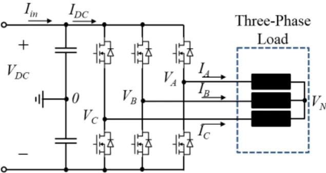
phase. Characteristics of this converter will be used as reference in this paper and the electrical circuit representing this converter can be seen in Fig. 1. One of first SiC MOSFET modules found in the market which could be used to cope with such power and voltage is the half bridge 1200V/100A SiC MOSFET module from CREE, reference CAS100H12AM1. Characterization of this SiC module will be performed in order to shown the trade-off between losses and EMI issues on three-phase inverters using SiC technology.
Fig. 1: Basic three-phase inverter circuit Characterization of SiC module
Calculation of semiconductor losses in three-phase inverters depend on conduction and switching losses. Conduction losses can be calculated using information provided by component’s datasheet. Switching losses are not always possible to calculate using datasheet because either there is not enough data given by manufacturers or because they may not be representative of losses in the real converter.
Switching energies in datasheets are often measured using the “double pulse” method. This method has serious drawbacks including current sensing using resistors or current transformer which changes the commutation loop resistance and the current in the transistor’s parasitic capacitance which is not measured by this method. As a consequence, the calculated switching energy may be inaccurate, especially when it is applied to fast switches such as SiC transistors. A more accurate method for measuring switching losses in fast components such as SiC and GaN transistors is called the “modified opposition method” and is explained in [4]. This method consists of an association of two identical half bridges containing the 4 identical devices (SiC MOSFETs in this case) supplied by the same source. One half-bridge operating as a generator and the other as a receptor. An inductive link connects both converters and the control of the current flowing from one half-bridge to the other is made by small differences applied to the duty cycle and phase-shift of applied switching signals of both half-bridges. Like this, one can estimate turn-on and turn-off losses separately. We applied this method in a test bench used for measurement of switching characteristics. A test board, specifically designed to characterize the CAS100H12AM1 SiC module, is presented in Fig. 2. As
a result, the variation of switching losses, switching speed (dv/dt) and also overshoot with circuit parameters (DC bus voltage Vdc and current I) and driver parameters (gate-source voltage Vgs, gate resistance
Rg and dead time DT) are available from the module
characterization.
Fig. 2: Developed test board used for switching energy measurements specifically designed for the CAS100H12AM1 modules.
a)
b)
Fig. 3: Relationship between turn-on and turn-off energies and a) switching speed and b) overshoot, for different Rg, at Vdc=540V and Iout=50A.
As an example of the experimental results described above, Fig. 3a shows the relationship between switching energies (turn-on and turn-off), dv/dt and gate resistance at 50A, for a DC bus voltage of 540V and
Vgs=20V. The same is shown in Fig. 3b, but related to
the overshoot and not dv/dt.
These figures show that the smaller the Rg is, the higher switching losses are but the lower are the overshoot and switching speed dv/dt. Note that, when changing Rg from 10 to 1Ω, total energy (on + turn-off) decrease from around 2850 to 930 µJ (3 times lower switching losses). However, maximum dv/dt and overshoot increase 1.5 and 4 times, respectively. Losses, dv/dt and overshoot in three-phase inverters
Having the experimental data described above, one can evaluate losses of a three-phase inverter and associate it to dv/dt and overshoot values. This is done using a MATLAB algorithm to calculate transistors switching and conduction losses for different converter’s switching frequencies and output current per phase. Three configurations are evaluated, including a IGBT for comparison purposes: 1 – using the Si IGBT SK100GB12T4 module (referred here as “IGBT Datasheet”); 2 – using the SiC module based on the previous characterizations having Rg=5Ω and Vgs=20V (referred here as “SiC R5”); 3 – using the same SiC module, based on the previous characterizations having
Rg=1Ω and Vgs=20V (referred here as “SiC R1”). The last configuration is the one where one can reduce the most losses in the SiC module. For the four different configurations, total losses in one phase are calculated for nominal power, i.e. for 80A RMS current per phase and for two different switching frequencies Fsw, 15kHz
and 60kHz. Calculation was made considering sinusoidal output currents in phase with the output voltage (i.e. resistive load), having negligible current ripple at room temperature. Results of this calculation is shown in Table 1.
Besides the values concerning losses, we have added the average switching speed and the maximum overshoot for each configuration. They were calculated using experimental results for the SiC and using the datasheet values for the IGBT. Note that at low switching frequency (15kHz) there are about 2.5 lower losses when using SiC MOSFET when compared to IGBT. At high frequency (60kHz), the fact of reducing the gate resistance from 5 to 1Ω, and increasing the gate-source voltage, total losses of SiC module decreases 2 times. However, this loss reduction increased dv/dt of 50% and doubled the maximum overshoot.
Data shown in Table 1 is not sufficient to preview EMI issues in converters. For this, dv/dt and overshoot must be known for each commutation of an entire period of the output current. Thus, an algorithm was developed to
calculate dv/dt and overshoot for each switching period based on experimental results. This data is suitable to be used in algorithms to calculate EMI and filter needs due to high switching speed, as it will be shown in the next section. IGBT Datasheet SiC R5 SiC R1 Total Losses Fsw=15 kHz 423W 150W 119W Fsw=60 kHz 1323W 276W 169W Average Switching Speed 10kV/µs 20kV/µs 30kV/µs Max Overshoot N/A 100V 220V Table 1: Calculated losses in one phase, dv/dt and overshoot for different configurations on a 540V/45kVA/80A three-phase inverter using IGBT or SiC MOSFET.
EMI of three-phase inverters using SiC modules The use of SiC semiconductors will contribute to significantly increase the power density of electromechanical drives. However, the introduction of this emerging technology contributes to an electromagnetic environment degradation with the increase of the Electromagnetic Interferences (EMI). Higher switching speeds causes a greater excitation of the converter’s parasitic elements (stray capacitances and stray inductances of the commutation loop). Knowing that conducted disturbances lead to premature roller bearings damage in motors [5], EMI must not exceed the permissible levels. When results are not compliants with the EMI standard, here the commercial aircraft standard DO160-G [6], one or more passive EMI filters have to be added to efficiently reduce electromagnetic interference emissions; especially common-mode (CM) conducted noise emissions, which are the most disturbing in any variable-speed drive systems. We will then focus on the impact of SiC inverter in the output CM filter
In order to calculate the cut-off frequency of this filter and consequently design it, the switching waveforms between the output of a phase-leg and the middle point of the DC bus have to be determined for each switching period of a load current fundamental period.
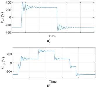
A well-known practice to represent this switching voltage is to simply model it by a trapezoidal waveform. The idea here is to increase the accuracy of this waveform by adding the information of dv/dt and overshoot experimentally obtained and shown above. Besides that, another information issued from experimental data is needed such as the oscillation frequency and dumping right after the commutation. These two parameters are mainly dependent on the circuit parasitic inductance, capacitance and resistance and do not significantly change with the driver
parameters and output current. As a results, the trapezoidal waveform is modified as shown in Fig. 4a, which is a much better representation of an actual experimental waveform.
In a three-phase inverter, the common-mode voltage
VCM can be defined as done in the following equation. VCM = (VA0+VB0+VC0)/3
where VA0, VB0, VC0 are the voltage between the
respective phase and the DC bus mid-point. The result of this equation for a given switching period is shown in Fig. 4b.
a)
b)
Fig. 4: Accurate representation of a) output phase to DC bus mid-point voltage and b) output common-mode voltage based on the combination of trapezoidal waveform and local oscillation information available from experimental results.
The electromechanical drive can be modeled with a quadripolar approach as shown in Fig. 5. Actually, we are mainly interested on the common mode currents generated by the inverter and not on the common currents from a potential mode transfer from DM to CM due to non-symmetric loads.
Fig. 5: Common-mode modelling approach of electromechanical chain.
Using this approach, studies can be made to determine the influence of the use of SiC MOSFET and also the influence of circuit parameters (DC bus voltage and current) and driver parameters (gate-source voltage, gate resistance and dead time DT), as it was shown before related to losses. As an example, Fig. 6 shows the spectrum of the common-mode current ICM at the
output of the inverter calculated using the approach presented here, for a gate resistor value of 10 and 1Ω.
Note that, in the frequency range from 6 to 100 MHz, using Rg=1Ω, ICM has much higher harmonic
amplitudes (about 20dB higher at 37MHz) than using
Rg=10Ω. This leads to larger high-frequency CM filters, although switching losses can be reduced to 1/3.
Fig. 6: Effect of the gate resistor value on the inverter’s output CM current.
Conclusions
The use of SiC components in three-phase inverters was investigated in this paper. The advantages of reducing losses due to fast commutation is quantified experimentally for the variation of different circuit and driver parameters. It was also explained and quantified the disadvantage of such fast commutation on Electromagnetic Interference (EMI) issues in the converter and load connected to it.
We have presented a generic approach to evaluate the trade-offs between losses and EMI issues of three-phase inverters which is precise and suitable for fast switches such as SiC and GaN transistors.. Some results show that, as an example, reducing the gate resistance from 10 to 1Ω, a SiC inverter may present 3 times lower switching losses although the maximum dv/dt of the output voltage increases 50% and larger high-frequency CM filters is necessary to filter an extra 20dB at 37MHz of the output CM current.
References
1 M. Todeschi, Airbus “EMAs for flight controls actuation system 2012 status and perspectives”, Recent Advances in Aerospace Actuation Systems and Components, Toulouse France. June 2012.
2 L. Prisse, D. Ferer, H. Foch, A. Lacoste, “New power centre and power electronics sharing in aircraft”, 13th European Conference on Power Electronics and Applications (EPE), Barcelone, Spain. Sept. 2009. 3 X. Giraud, M. Budinger, X. Roboam, H. Piquet, M. Sartor, J. Faucher, “Optimal design of the integrated modular power electronics cabinet”, Aerospace Science and Technology, vol. 48, pp. 37–52, 2016.
4 B. Cougo, H. Schneider, T. Meynard, “Accurate switching energy estimation of wide bandgap devices used in converters for aircraft applications”, (2013) 15th European Conference on Power Electronics and Applications (EPE), Sept. 2013.
5 ABB. “Guide technique No.5. Les courants de palier dans système d’entraînement c.a. à vitesse variable”, 2012.
6 Environmental Conditions and Test Procedures for Airborne Equipment, DO160-G, Section 21, 2014.