HAL Id: hal-02420238
https://hal.archives-ouvertes.fr/hal-02420238
Submitted on 19 Dec 2019HAL is a multi-disciplinary open access archive for the deposit and dissemination of sci-entific research documents, whether they are pub-lished or not. The documents may come from teaching and research institutions in France or abroad, or from public or private research centers.
L’archive ouverte pluridisciplinaire HAL, est destinée au dépôt et à la diffusion de documents scientifiques de niveau recherche, publiés ou non, émanant des établissements d’enseignement et de recherche français ou étrangers, des laboratoires publics ou privés.
Gilblas, Stéphane Orieux, Stéphane Colin, Yannick Le Maoult
To cite this version:
Georges Saliba, Lucien Baldas, Vincent Raimbault, Ahmad Batikh, Rémi Gilblas, et al.. Study and development of fluidic oscillators for heat removal. istegim2019 - Proceedings of the International Symposium on Thermal Effects in Gas flows In Microscale, Oct 2019, Ettlingen, Germany. pp.1-6. �hal-02420238�
istegim2019:285128
STUDY AND DEVELOPMENT OF
FLUIDIC OSCILLATORS FOR HEAT REMOVAL
Georges Saliba*1, Lucien Baldas1, Vincent Raimbault2, Ahmad Batikh1, Rémi Gilblas1, Stéphane Orieux1, Stéphane Colin1, and Yannick LeMaoult1
1Institut Clément Ader (ICA), Université de Toulouse, CNRS-INSA-ISAE-Mines Albi-UPS, Toulouse, France 2LAAS-CNRS, Université de Toulouse, 7 Avenue du Colonel Roche, BP 54200, 31 031 Toulouse , France.
Abstract
The aim of this project is to evaluate the viability of fluidic oscillators as a means of improving heat transfer rates. The particular device considered herein produces two out-of-phase pulsed impinging jets as opposed to the sweeping jets inherent to other designs in the field of fluidics. The first stage of this project will consist in studying a sub-millimeter prototype (whose smallest channel is200µm wide), both numeri-cally and experimentally, to figure out whether or not improving heat transfer rates is possible. A parametric study is conducted to better understand the effects of pulsation frequency, waveform, amplitude as well as a number of geometric factors such as nozzle-to-plate distance. The prototype is made by stereo-lithography using a medical-grade polymer. The temperature field is measured using an infrared camera. This prelimi-nary study showed qualitative agreement with the literature in terms of the shape of the temperature profiles.
Keywords: heat transfer, oscillators, microsystems, pulsed jets, impinging jet
1. INTRODUCTION
In our day and age, industries heavily rely on electronics in the design of their products. And with increasing dependence on electronics there is a high demand for efficient cooling solutions that are both cost-effective and low-maintenance. The go-to solution when it comes to cooling a heated solid is often impinging jets. They are simple to set up and in certain cases can achieve heat flux densities greater than500 MW m−2. A number of studies over the years have tried to understand the effects of introducing a deterministic oscillatory component to a steady jet on its heat transfer performance. More specifically, the effect of each characteristic of these periodic disturbances has been studied in order to pinpoint the configuration for which the enhancement in heat transfer compared to an equivalent steady jet is largest. The characteristic that is most often studied is the pulsation frequency. Investigations such as Zumbrunnen and Aziz [1] and Zumbrunnen [2] focused on the nonlinear response of the thermal boundary layer to external forcing in order to understand how to improve heat transfer rates. Others like Hofmann et al. [3] sought to better comprehend how coherent structures (responsible for the surface renewal effect demonstrated by Kataoka et al. [4]) can be amplified by modulating the pulsation frequency.
Another important factor is the nozzle-to-plate distance whose precise effects on pulsed impinging jets remains unclear. Two relatively recent studies Esmailpour et al. [5] and Alimohammadi et al. [6] studying very similar configurations arrived at completely different conclusions regarding the effect of nozzle-to-plate distance on relative performance.
Other more specific parameters such as phase difference (Chaniotis, Poulikakos, and Ventikos [7]) and waveform (Geng, Zheng, and Zhou [8], Mohammadpour et al. [9] and Zhang, Li, and Xie [10]) have also been extensively studied in recent times.
It is worth noting at this point that most experimental studies have relied on some mechanism, like a rotating valve, in order to produce the unsteady jet. When it comes to using self-oscillating systems for heat transfer, the literature is scarce. Some recent (Zhou et al. [11]), relatively recent (Narumanchi et al. [12]) and not so recent (Herr and Camci [13]) studies have used sweeping jet variants of the fluidic oscillator for heat transfer. In comparing with steady jets at the same mean mass flow rate, Narumanchi et al. [12] found an improvement of30% while Zhou et al. [11] observed a clear deterioration in performance. The latter attribute their results to the decrease in velocity caused by oscillating the jet which is not offset by the production of turbulent kinetic energy. Zheng et al. [14] have also used oscillators for heat transfer, but this time to produce a pulsating pipe flow. To the extent of our knowledge, no significant study has used a fluidic oscillator to produce pulsating impinging jets for heat transfer.
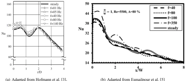
(a) Adapted from Hofmann et al. [3], (b) Adapted from Esmailpour et al. [5]
Figure 1: Nusselt number profile along heated plates cooled by means of steady and periodically excited jets impinging from close distances, showing the typical secondary and tertiary peaks associated with small standoff distances and unsteady jets respectively.
2. NEGATIVE FEEDBACK OSCILLATOR
The oscillator studied here was dubbed the “negative feedback oscillator” Warren [15] by its inventor, Raymond W. Warren in 1964. As can be seen in figure 2, this device is made up of a supply nozzle, two angled branches stemming from an interaction region and two feedback loops. The jet exiting the supply nozzle entrains stagnant fluid around it. Due to hydrodynamic instability (see Michalke [16] for more details on the causes and effects of jet instability), the drop in pressure on both sides of the jet is not symmetrical at any given moment. And seeing that we are dealing with a closed space, the instability keeps increasing until the pressure gets low enough on one wall for the jet to attach itself to it. When this happens, the jet is redirected into the corresponding branch and is divided downstream between the exit and feedback loop apertures. The flow entering the feedback loop is then redirected to the control port. A pressure wave is also formed on the same side of the oscillator. These two phenomena eventually result in the deflection of the main flow which then switches to the other side. This process then repeats itself ad infinitum.
Cerretelli and Gharaibah [17] have recently studied a similar oscillator and found that the frequency response to inlet pressure was different depending on the volume of the feedback loop. For relatively large feedback volumes the frequency of pulsation is no affected by the inlet pressure. On the other hand, for smaller volumes, the frequency kept increasing with inlet pressure (even though the length of the feedback loop was left unchanged until it reached saturation at aroundf = 2500 Hz for pinlet/patm= 2
According to Simões et al. [18], who studied a microscale version of this oscillator, the frequency of pulsa-tion is given by:
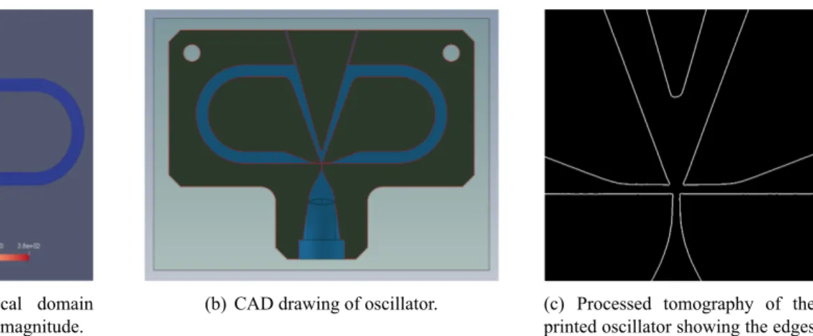
(a) Truncated numerical domain showing mean velocity magnitude.
(b) CAD drawing of oscillator. (c) Processed tomography of the printed oscillator showing the edges of the interaction zone.
Figure 2: Elaboration of the prototype from numerical simulation to 3D-printing by stereolithography
f = 1 2 1 τt+ τs = 1 2 1 l c + ξL u (1)
whereτtis the transmission time,τsis the jet switching time,c is the speed of wave propagation, L is the
nozzle-to-splitter distance and, finally,ξ is an empirical constant.
Wang et al. [19] conducted further studies and showed through numerical simulation that the switching phenomenon was mainly driven by the back and forth propagation of a pressure wave in the feedback loop. In light of that, the following relationship was proposed:
T = 1 f = 4l c + τs = 4l c0+ V + τs (2) wherec≈ c0+ V is the average propagation velocity of the pressure wave inside the oscillator, c0the speed
of sound,V local velocity of the fluid and τs, as before, the switching time.
Finally, Tesař and Peszynski [20] posit that this type of oscillator should have a constant Strouhal number: St = f b
w (3)
wheref is the switching frequency of the inlet jet, b its width (for a two-dimensional configuration) and w the jet bulk velocity. IfSt =const. then we should end up with:
f ∝ ˙m (4)
The experiments they conducted revealed a different behavior. Although the relation between frequency and mass flow rate was found to be linear, the intercept was non-zero. The authors do not provide a physical explanation for this aberration.
Coming back to the present study, the prototypes used were made by stereolithography at the MultiFab platform of the LAAS-CNRS Laboratory. The 3D printer available is setup in the so-called ”bat configuration”, meaning that the stage is plunged in a vat filled with resin that is solidified by a laser-mirror-lens system under-neath. The smallest channel in the current prototype is only200µm wide (at the throat inlet of the oscillator).
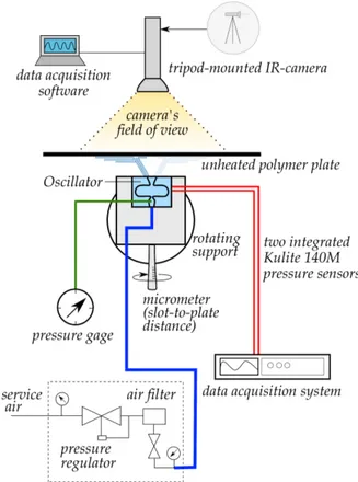
Figure 3: Setup of the preliminary experiment with an unheated polymer plate.
3. EXPERIMENTAL SETUP
The setup for the experimental part is relatively simple. The oscillator is pinned to a sliding platform equipped with a micrometer in order to control the nozzle-to-plate distance. This platform is then attached to a rotating support to ensure that the top face of the oscillator is parallel to the plate .The pulsed jets impact the obverse of the plate while thermal images are being taken on the reverse via an uncooled infrared detector. The particular camera used (SC325) has a maximum thermal resolution of50 mK and, for the configuration used, a pixel size of around 25 µm. The frequency of the oscillator is detected using a Kulite XT-140(M) series subminiature pressure transducer placed at the surface, midway along one of the feedback loops.
As a preliminary test, a non-heated plate is used. The plate is a1.4 mm-thick piece of thermoplastic polymer (acrylonitrile butadiene styrene or ABS for short) having the following physical properties:
• Density: ρ = 1050kg m−3
• Specific heat: cp = 1300J kg−1K−1
• Thermal conductivity:κ = 0.19W m−1K−1 • Emissivity: ε = 0.94
Owing to the low acquisition frequency of the thermal detector, what we are able to measure is a time-averaged temperature field.
4. RESULTS & DISCUSSION
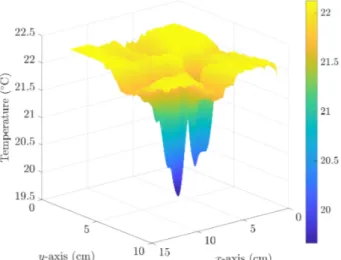
After removing the background noise from the original images and processing them we were able to extract the temperature field as can be seen in figure 4 .
The temperature profile has the features one would expect for a pulsed jet impacting from a short distance, namely a primary trough corresponding to the stagnation point followed closely by a secondary local trough
Figure 4: Temperature field around the impact area with a nozzle-to-plate distance ofH/D = 1
indicating the acceleration of the flow along the plate and finally tertiary troughs a bit farther downstream that characterize pulsed impinging jets (see caption to figure 1). The lack of symmetry in the temperature field present here was the result of a flaw in the fabrication of the prototype. Experiments on a new and improved device are underway.
The frequency of the oscillator, detected by the pressure transducer, was found to be around 1080 Hz re-gardless of inlet pressure. By simulating the exact oscillator on OpenFOAM © we had previously obtained a frequency of970 Hz.
5. CONCLUSIONS
This proof-of-concept setup is the first of a series of experiments to determine the effect of nozzle-to-plate distance, pulsation frequency and velocity on the heat transfer performance of a pulsed impinging jet produced by a fluidic oscillator. The next step would be to replace the unheated polymer plate with a heated metallic plate equipped with heat flux sensor in order to more closely correlate the pulsation signal with the thermal response of the plate. A speedier infrared camera will then be used to capture instantaneous fields of temperature on the reverse of the plate.
The following stage of the project is to make a 1 : 10 scale prototype and to see first whether or not the oscillator still functions at this scale and second to study the possibility of synchronizing an array of oscillators and testing their ability to remove heat in highly confined spaces.
ACKNOWLEDGMENTS
This work was partly supported by the Fédération de Recherche FERMaT, FR 3089, Université de Toulouse, France.
REFERENCES
[1] D. A. Zumbrunnen and M. Aziz. “Convective Heat Transfer Enhancement Due to Intermittency in an Impinging Jet”. In: Journal of Heat Transfer 115.1 (1993), p. 91.
[2] D. A. Zumbrunnen. “Transient Convective Heat Transfer in Planar Stagnation Flows With Time-Varying Surface Heat Flux and Temperature”. In: Journal of Heat Transfer 114.1 (1992), p. 85.
[3] H. M. Hofmann, D. L. Movileanu, M. Kind, and H. Martin. “Influence of a pulsation on heat transfer and flow structure in submerged impinging jets”. In: International Journal of Heat and Mass Transfer 50.17-18 (2007), pp. 3638–3648.
[4] K. Kataoka, M. Suguro, H. Degawa, K. Maruo, and I. Mihata. “The effect of surface renewal due to large-scale eddies on jet impingement heat transfer”. In: 30 (1987), pp. 559–567.
[5] K. Esmailpour, M. Hosseinalipour, B. Bozorgmehr, and A. S. Mujumdar. “A numerical study of heat transfer in a turbulent pulsating impinging jet”. In: The Canadian Journal of Chemical Engineering 93.5 (2015), pp. 959–969.
[6] S. Alimohammadi, P. Dinneen, T. Persoons, and D. B. Murray. “Thermal management using pulsating jet cooling technology”. In: Journal of Physics: Conference Series 525.1 (2014).
[7] A. K. Chaniotis, D. Poulikakos, and Y. Ventikos. “Dual Pulsating or Steady Slot Jet Cooling of a Constant Heat Flux Surface”. In: Journal of Heat Transfer 125.4 (2003), p. 575.
[8] L. Geng, C. Zheng, and J. Zhou. “Heat transfer characteristics of impinging jets: The influence of un-steadiness with different waveforms”. In: International Communications in Heat and Mass Transfer 66 (2015), pp. 105–113.
[9] J. Mohammadpour, M. M. Zolfagharian, A. S. Mujumdar, M. R. Zargarabadi, and M. Abdulahzadeh. “Heat transfer under composite arrangement of pulsed and steady turbulent submerged multiple jets im-pinging on a flat surface”. In: International Journal of Thermal Sciences 86 (2014), pp. 139–147. [10] Y. Zhang, P. Li, and Y. Xie. “Numerical investigation of heat transfer characteristics of impinging
syn-thetic jets with different waveforms”. In: International Journal of Heat and Mass Transfer 125 (2018), pp. 1017–1027.
[11] W. Zhou, L. Yuan, Y. Liu, D. Peng, and X. Wen. “Heat transfer of a sweeping jet impinging at narrow spacings”. In: Experimental Thermal and Fluid Science 103.November 2018 (2019), pp. 89–98.
[12] S. Narumanchi, K. Kelly, M. Mihalic, S. Gopalan, R. Hester, and A. Vlahinos. “Single-phase self-oscillating jets for enhanced heat transfer”. In: Annual IEEE Semiconductor Thermal Measurement and Management Symposium (2008), pp. 154–162.
[13] F. Herr and C. Camci. “Self-oscillating-impinging-jet as a gas turbine cooling enhancement system”. In: Proceedings of the ASME Turbo Expo 3 (1997).
[14] J. Zheng, D. Zeng, P. Wang, and H. Gao. “An experimental study of heat transfer enhancement with a pulsating flow”. In: Heat Transfer - Asian Research 33.5 (2004), pp. 279–286.
[15] R. W. Warren. Negative Feedback Oscillator. 1964.
[16] A. Michalke. “Survey on jet instability theory”. In: Progress in Aerospace Sciences 21.C (1984), pp. 159– 199.
[17] C. Cerretelli and E. Gharaibah. “An Experimental and Numerical Investigation on Fluidic Oscillators For Flow Control”. In: June (2012).
[18] E. W. Simões, R. Furlan, R. E. Bruzetti Leminski, M. R. Gongora-Rubio, M. T. Pereira, N. I. Mori-moto, and J. J. Santiago Avilés. “Microfluidic oscillator for gas flow control and measurement”. In: Flow Measurement and Instrumentation 16.1 (2005), pp. 7–12.
[19] S. Wang, L. Baldas, S. Colin, S. Orieux, A. Kourta, and N. Mazellier. “Experimental and Numerical Study of the Frequency Response of a Fluidic Oscillator for Active Flow Control”. In: June (2016), pp. 1–15. [20] V. Tesař and K. Peszynski. “Strangely behaving fluidic oscillator”. In: EPJ Web of Conferences 45 (2013),