HAL Id: hal-00930191
https://hal.archives-ouvertes.fr/hal-00930191
Submitted on 14 Jan 2014
HAL is a multi-disciplinary open access archive for the deposit and dissemination of sci-entific research documents, whether they are pub-lished or not. The documents may come from teaching and research institutions in France or abroad, or from public or private research centers.
L’archive ouverte pluridisciplinaire HAL, est destinée au dépôt et à la diffusion de documents scientifiques de niveau recherche, publiés ou non, émanant des établissements d’enseignement et de recherche français ou étrangers, des laboratoires publics ou privés.
Electromagnetic modeling and definition of antenna
specifications and positions for radio system deployment
in confined environments
Jorge Avella-Castiblanco, Divitha Seetharamdoo, Marion Berbineau, Michel
Ney, François Gallée
To cite this version:
Jorge Avella-Castiblanco, Divitha Seetharamdoo, Marion Berbineau, Michel Ney, François Gallée. Electromagnetic modeling and definition of antenna specifications and positions for radio system deployment in confined environments. IOP Conference Series: Materials Science and Engineering, IOP Publishing, 2013, 44 (1), 5p. �10.1088/1757-899X/44/1/012010�. �hal-00930191�
This content has been downloaded from IOPscience. Please scroll down to see the full text.
Download details:
IP Address: 137.121.1.26
This content was downloaded on 04/10/2013 at 14:55
Please note that terms and conditions apply.
Electromagnetic modeling and definition of antenna
specifications and positions for radio system
deployment in confined environments
J. Avella Castiblanco1 , D. Seetharamdoo1 , M. Berbineau1 , M. Ney2 , F. Gallee2
1 IFSTTAR, LEOST, 20 Rue Elise Reclus - BP 70317 - 59666 Villeneuve D’Ascq Cedex,
France.
2 Telecom Bretagne, Dept. Microondes, Brest, France.
E-mail: jorge.castiblanco@ifsttar.fr, divitha.seetharamdoo@ifsttar.fr
Abstract. In this paper, the definition of antenna specifications for radio system deployment as well as a methodology to integrate them in confined environments is presented. Modal-based analysis and optimization techniques for mode-weight adjustments are used to determine correct co-excitation of the propagating modes and fulfill the desired specifications.
1. Introduction
Wireless communication system design in confined environments is complex due to harder electromagnetic and spatial constraints. Indeed the number of on-board wireless systems is increasing and polymers are increasingly used to build modern, lighter railway vehicles. The investigation on novel antennas is of outstanding importance to guarantee reliable communication for systems such as control-command. Appropriate methodologies for antenna design and integration have to be developed to face the challenges on such platforms.
Research work on antenna integration in railway environments by using metamaterials is performed in the framework of the METAPHORT project initiated by the French National Institute of Science and Technology for Transport (IFSTTAR). The aim of this project is to develop metamaterial antennas and to establish a methodology for the antenna integration in urban underground railways. Train-to-Wayside communication systems for control command applications for railways in an urban underground environment based on 802.11 a and 802.11 g WLAN standards are considered. Antenna integration in this environment requires appropriate numerical models of the electromagnetic wave propagation accounting for multi-scale geometries such as tunnels and objects, and in a reasonable computation time. Appropriate methodologies for the antenna integration based on these models will be proposed and validated.
The paper is organized as follows. Section 2 presents a methodology for the correct antenna integration. Results using our methodology is shown in section 3. Finally, conclusions and on-going work are developed.
Radio and Antenna Days of the Indian Ocean (RADIO 2012) IOP Publishing IOP Conf. Series: Materials Science and Engineering 44 (2013) 012010 doi:10.1088/1757-899X/44/1/012010
2. Methodology for Meta-material antenna design
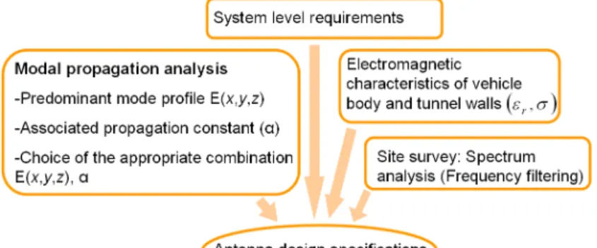
Metamaterials can be described as artificial media tailored to control wave propagation. They can provide a higher degree of freedom in the design of antennas for wireless systems tailored for specific environments by controlling the EM energy stored or radiated around the antenna. For the development of novel antenna solutions in tunnels different inputs are required as depicted in Fig. 1.
Figure 1. Novel metamaterial antenna design methodology.
2.1. Antenna design for tunnels
The specifications and parameters involved in the antenna design for confined environments, such as tunnels, have not yet been established in the scientific or technical literature. A few considerations on the obstruction, separation, installation and maintenance can be found in the U. K. guidance on train rooftop antenna positioning (GK/GN06602) as well as by some manufacturers. However, the problem of antenna operation in tunnel environments is not addressed. Thus, a methodology for antenna design is needed and appropriate models providing physical insight must be considered. Various studies have been done considering several models to analyze radiation characteristics and positioning of antennas in tunnels [1] or simply to model the wave-propagation in these environments [2]. These models are based on asymptotic approaches and they thus fail for antennas which are strongly affected by the surrounding environment. A novel methodology for finding appropriate field specifications and optimum antenna positioning can be obtained by using a modal approach with a full-wave method, such as the Transmission Line Matrix method (TLM) [3].
2.2. Methodology for finding antenna specifications
An efficient modal approach for the analysis of guiding structures is applied to find the fields [4]. Different optimum positions and types of excitation are involved due to multi-modal propagation in these environments. These modes may be combined in some way to produce a desired effect, e.g., the maximization of the power transferred by the modes.The particularity of this approach is that only the cross-section of the tunnel is considered while modeling the field propagation in the longitudinal direction. Tunnels with arbitrary cross section, loaded or unloaded, can be analyzed with this approach.
2.2.1. Description of the Methodology The proposed methodology is divided into five steps. The first one concerns the calculation of the characteristic mode parameters α, β, Eb(x, y) and
b
H(x, y). Second, the modes are discriminated by their power carried through the tunnel so
that only modes with the highest power are considered. Then, an optimization procedure of the transmitted power on the weight coefficients is carried out. A constrained solution in terms of the maximum or minimum power density that can be transmitted or received, respectively, must be found. In the fourth step, the optimum weight coefficients to maximize the mean power along the propagation direction are obtained. Finally, the optimum fields specifications, type of excitation and source positioning are determined by using the optimum weights. A detailed description of this methodology can be found in [3].
3. Results
The wave propagation in a rectangular tunnel with transverse dimension w = 7m × h = 5m was considered. The tunnel walls were modeled by a lossy dielectric with ϵr= 12 and σ = 0.02Sm−1.
The power density specifications were defined to be 0 dB Wm−2 at z
T x = 0 and -40 dBWm− 2
at zRx= 1, 000 m. This tunnel was simulated using our modeling approach. The attenuation, phase
constants, and the field profiles of the Ey11and E11x modes were determined and compared with
Marcatilli’s approximate theory, results are shown in Fig. 2. The attenuation and dispersion
Figure 2. Attenuation, dispersion and field profiles for the Ey11and E11x modes.
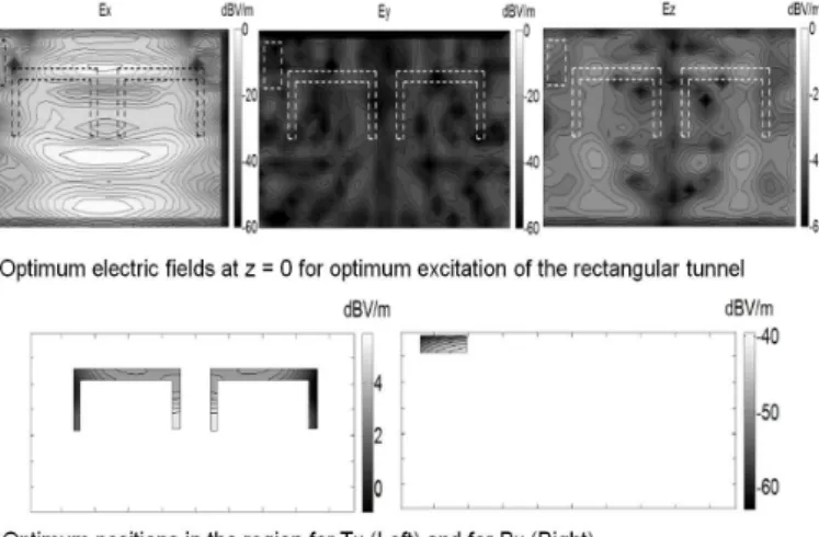
characteristics calculated by our modeling approach are in good agreement with Marcatilli’s theory. However, the attenuation constants obtained for low frequencies are different most probably due to the fact that in Marcatilli’s approach the fields at the corners are canceled unlike in our numerical method. The optimum electric fields to excite the rectangular tunnel are then calculated by using the above results from the modal approach; optimum weight coefficients are then defined using our methodology. Optimum positions where the mean power along the longitudinal distance is maximum were also calculated. By way of illustration, the three field components of the electric field that satisfy the power density specifications in Tx were calculated at z = 0, as shown in Fig. 3.
Intuitively, one could expect that optimum fields are most influenced by the lowest attenuated modes. This result can be confirmed by observing that the points where the x-component of the electric field in Fig. 3 is minimum at corners, and the z-component is minimum at half of the width as it occurs for the Ex
11mode. This observation can also be confirmed as the x-component
is maximum at one-third, as well as one-quarter of the width as for both Ex
21 and E31x modes.
Radio and Antenna Days of the Indian Ocean (RADIO 2012) IOP Publishing IOP Conf. Series: Materials Science and Engineering 44 (2013) 012010 doi:10.1088/1757-899X/44/1/012010
Figure 3. Modeling approach.
Optimum positions to locate the transmitter are those where the mean power along the longitudinal distance is maximum, i.e., for the points close to the white regions in Fig. 3. 4. Conclusions
A methodology for the definition of antenna specifications for radio system deployment and antenna integration in confined environments has been presented. The methodology relies on a numerical model based on modal analysis. Then, optimization techniques were applied, and mode-weight adjustments are used to determine correct co-excitation of the propagating modes and ensure a good power transfer from the transmitter to the receiver. Results are presented for a tunnel in terms of complex propagation constant and mode profiles. Good agreement with an approximate model has been shown, thus validating our numerical results. The antenna design methodology for positioning and determination of specifications was then applied. It should be noted that this methodology has to be repeated for all the critical scenarios varying for traffic considerations, different tunnel cross sections, multiple tracks and different distances between the transmitter and receiver.
Acknowledgments
This work was funded by the French National Agency within the ANR-VTT 2009 program in the framework of the METAPHORT project. The authors also acknowledge support from the I-TRANS railway cluster of the Nord Region of France, as well as the Images et Reseaux cluster of the Brittany region.
5. References
[1] Y. Huo, Z. Xu, H. dang Zheng, and X. Zhou, “Effect of antenna on propagation characteristics of electromagnetic waves in tunnel environments,” in Microelectronics Electronics, 2009. PrimeAsia 2009. Asia Pacific Conference on Postgraduate Research in, Jan. 2009, pp. 268 –271.
[2] D. Didascalou, “Ray-optical wave propagation modelling in arbitrarily shaped tunnels,” Ph.D. dissertation, Institut fur Hochstfrequenztechnik und Elektronik der Universitat Karlsruhe (TH), 2000.
[3] J. Avella Castiblanco, D. Seetharamdoo, M. Berbineau, M. Ney, and F. Gallee, Wave propagation. Chapter: ”Electromagnetic wave propagation modeling for finding antenna specifications and positions in tunnels of arbitrary cross-section”., ser. ISBN 980-953-307-493-6. INTECH, 2012.
[4] ——, “Surface boundary conditions for lossy dielectrics to model electromagnetic wave propagation in tunnels,” European Conference on Antennas and Propagation (EUCAP), pp. 2331 – 2335, April 2011.