Science Arts & Métiers (SAM)
is an open access repository that collects the work of Arts et Métiers Institute of
Technology researchers and makes it freely available over the web where possible.
This is an author-deposited version published in: https://sam.ensam.eu Handle ID: .http://hdl.handle.net/10985/17195
To cite this version :
Yafang LI, Philippe DELARUE, Philippe LE MOIGNE, Frédéric COLAS, Xavier GUILLAUD - Full State Regulation of the Modular Multilevel DC converter (M2DC) achieving minimization of circulating currents - IEEE Transactions on Power Delivery p.1-1 - 2019
Any correspondence concerning this service should be sent to the repository Administrator : [email protected]
Abstract— The M2DC exploits the interleaving between the
three legs of an MMC to realize a promising uninsulated DC/DC converter to interconnect HVDC grids. This paper details a current and energies decoupled model of the M2DC. The major idea proposed in this paper is focused on the full energy control generating optimal current references to minimize the internal currents magnitude. The energy sum and difference models are fully detailed. Both current and energy control loops are based on the model inversion principle in order to control all the state variables. The proposed control is based a dynamic control developed with the model inversion principle associated with an optimization of the current magnitude deduced from a quasi-static analysis. All dynamics of the system are then explicitly controlled, which guarantee a good dynamic behavior during the transient. Therefore, current and energy controls are presented in detail. Simulation results show the dynamic behavior of the converter for various operating points.
Index Terms— Converter control, DC-DC modular multilevel
converter, HVDC converter, Modular Multilevel DC converter, M2DC, MMC
I. NOMENCLATURE
The upper and lower arm components are denoted by “ ” and “ ” as shows Fig. 1.
Equivalent upper and lower SM capacitance. Equivalent upper and lower equivalent Arm capacitance.
Lower side phase current. Differential current.
Upper and lower number of SM
Number of activated SMs in upper / lower arm Power reference set on the low voltage DC side Angle between and
Period, pulsation of AC variables Angle between and
Manuscript submitted December 21, 2018, revised in July 2019 and accepted in sept. 2019 to IEEE Trans on Power Delivery. F. Gruson, Y. Li, P. Le Moigne, P. Delarue, F. Colas and X. Guillaud are with Univ Lille, Centrale Lille, Arts et Metiers, HEI, EA 2697-L2EP - Laboratoire d’Electrotechnique et d’Electronique de Puissance, F-59000 Lille, France.
Angle between and Arm resistance and inductance. DC output resistance and inductance
; Decoupled modulated arm voltages, respectively (controlling ; )
Upper / lower modulated arm voltages
Upper / lower equivalent arm capacitor voltage. Phase stored energy
Difference energy between arms in a leg. II. INTRODUCTION
n the last decades, many HVDC links have been commissioned and many others are under development. Multi-Terminal DC grids (MTDC) have been proposed to build upon existing point-to-point HVDC links to increase their flexibility and robustness. The interconnections of existing HVDC schemes face however technical hurdles, coming primarily from differing voltage levels originating from incoordination between projects and evolving technology. DC/DC converters with a bidirectional power flow capability may thus be required. However, the voltage ratings of such converters prohibit the use of classic DC/DC topologies. As presented in [1] to [5], major topologies for DC/DC converters in the high-voltage area are based on the Modular Multilevel Converter (MMC) architecture, thanks to its modular property, high efficiency and growing technological maturity.
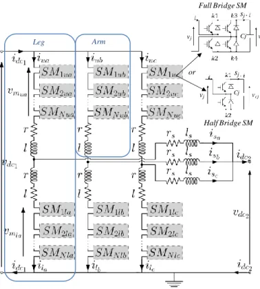
Among these various propositions, the Modular Multilevel DC Converter (M2DC) described in Fig. 1 offers an attractive uninsulated topology. It is composed of at least two interleaved legs, interconnected across the two DC terminal voltages. Each leg consists of two arms made of series-connected Sub-Modules (SMs). The topology of these SMs can be either of half-bridge and/or full-bridge types (see Fig. 1) depending if a DC-fault blocking capability is required on one DC bus or another, since this requires negative voltage capability.
The M2DC inherits some advantages from MMC [6], namely low switching frequency of individual semiconductors and low harmonic content in the current waveforms.
Full State Regulation of the Modular Multilevel
DC converter (M2DC) achieving minimization
of circulating currents
F. Gruson, Member, IEEE, Y. Li, P. Le Moigne, Member, IEEE P. Delarue, F. Colas, Member, IEEE ,
X. Guillaud, Member, IEEE,
Furthermore, the M2DC requires fewer submodules (SM) compared to the “Dual Active Bridge MMC topology” since the stacks only process part of the total converter power. This limits its overall cost and power losses (when a similar balancing control algorithm and therefore a similar switching frequency are used).
Several control challenges have already been identified in the MMC literature as noted in [7]-[8]. In the past decade, significant efforts have been poured into the modeling and control of the AC/DC original version of the MMC, but relatively few studies have been focused on the M2DC structure and, by extension, its control. The functioning principles of the M2DC were first proposed in [9], then its design and steady state operation validating the technological viability of the M2DC topology shortly after in [10]. Following publications combined design and control studies as in [11]-[12].
Fig. 1. Schematic representation of the M2DC.
Even if MMC and M2DC share similarities, a first major difference has to be highlighted: contrary the MMC, M2DC continuously requires internal AC currents to balance the stored energies in its upper and lower arms [11][12], even in steady state. As with the MMC, two different types of AC currents may be used: one AC current flows through the first DC terminal (top of legs in Fig. 1, circulating currents between the arms) and another one flow through the second DC terminal (middle of the legs in Fig. 1). In a MMC, these currents are the phase currents injected into the AC grid, with its frequency imposed by the grid and phase by the active and reactive operating point. In the M2DC, these AC currents are not injected into any AC grid. It can be concluded that additional degrees of freedom are available in the M2DC in the form of frequency, phase and amplitude of these internal AC components. Therefore, the control derived for the MMC has to be revisited for the M2DC. This is a second major difference.
Internal M2DC AC current components are collectively canceled at both the first and second DC terminals thanks to the interleaved leg operation, foregoing the use of AC filters. However, the choice of these new control parameters may have a very great influence on the magnitude of these AC currents and therefore on the sizing of the SM switches, capacitors and converter losses. For certain options, the magnitude of the AC current can be four times larger than the DC current. This phenomenon has been clearly explained in [11]. An optimization process is proposed to minimize the AC circulating internal currents of the M2DC. However, several state variables are not controlled. From the understandings made on the MMC, presented in [13] and [14] for the well-known Circulating Current Suppressing Control (CCSC), a partial control of state variables may induce instability of the converter. This partial control is interesting and open opportunities but potentially risky for HVDC applications. Moreover, as with CCSC in MMC, the lack of control of the upper arm current will generate a large transient current in case of DC fault.
The aim of this paper is to expand the idea developed in [12] in a more general control which ensures a full control of all the state variables of the M2DC in order to avoid the potential instabilities mentioned previously. For doing so, a methodology similar to MMC control methods (i.e. decoupling control & control of all leg state variables) is used but all the degrees of freedom with internal AC choices (eg frequency, amplitude, phase) are used to minimize the internal currents.
The average arm model and a static analysis of the M2DC are introduced in the section III. Then, the M2DC currents model and control are presented in section IV. Section V develops the M2DC energy models and controls. The last section presents the simulation results validating the proposed model and control scheme.
III. AVERAGE ARM MODEL AND STATIC ANALYSIS OF THE
MODULAR MULTILEVEL DCCONVERTER (M2DC) Since the three legs are similar (Fig. 1), the M2DC internal AC currents have the same amplitude and a phase shift equal to 2π/3 is generated between each leg to obtain a continuous current on each DC side as shown in [9] (a generalized M2DC with m legs would use a phase shift of 2π/m). Then, the analysis of the topology and the design of the control are focused on a single leg (Fig. 2) to simplify the presentation.
Due to the large number of SMs in the M2DC, a simplified averaged arm model is used for dynamic and steady-state analysis. This simplified averaged arm model is agnostic to the types of SMs used (e.g. half or full bridges) and considers that the balancing control algorithm of the voltage of each submodule is operating properly. Assumptions as well as the methodology to demonstrate the validity of this model are presented in [15].
For each arm, it is possible to define a modulated voltage and a modulated current where represents the upper ( ) or the lower ( ) arm:
Full Bridge SM Half Bridge SM or Leg Arm Cj v cj vj sj Cj vcj vj sj
(1)
(2)
is defined as the sum of all the submodules capacitor voltages in the arm . (1) and (2) are identical to an ideal chopper. An equivalent model composed of an ideal chopper and an equivalent capacitor could therefore replace the arm SMs. This equivalent average model of a M2DC leg is presented in the gray box of Fig. 2.
Fig. 2. Equivalent average M2DC arm model.
A simplified M2DC design is chosen to lighten the presentation of the original control. In this paper, capacitors
and are considered equal and named . In the sequel, all the losses are neglected. Let’s define
, , and as the DC components of and , and
(3) is defined as the power flowing through the M2DC.
, are the upper and the lower average arm powers generated by the above defined DC components. They have opposite values:
(4) Unlike MMC, these powers are not zero in steady state, as they are proportional to power and ratio α (ratio between the voltages and ) as presented in (4). The energy stored in the M2DC arms cannot remain stable naturally as the average powers in each arm are not equal to zero. Some AC components have to be introduced to stabilize the arm energies [11]. Some new notations also have to be introduced:
(5)
These components generate AC power in the upper and lower arm ( , ). The level of energy in the arm is stable if:
(6) Then, the aim of the control is to create the appropriate AC voltage components to stabilize the internal energy level.
The M2DC arm model is characterized by 4 independent state variables: the upper and lower equivalent arm capacitor voltages ( ), and two currents (for example one arm currents and the output current. The other arm current is therefore a consequence of the first 2 one). In consequence, the control needs four controllers to regulate each state variable independently. The DC component of the power manages the power flow through the converter. The AC component of the power guarantees the internal stability of the stored converter energy. The following sections describe the proposed original control.
IV. M2DCCURRENT MODEL LOOP DESIGN
In a first step, M2DC currents have to be controlled. For designing the control, a model is needed. Based on Kirchhoff laws, it is possible to determine the following relationships:
(7) (8) (9) (10) As for the MMC [6][15], these equations are coupled. New variables (11) are defined to design a controller for an uncoupled system:
(11)
Using (11) in (7) to (10) yields:
(12) (13) From these equations, the current model of the M2DC is created as shown in the upper part of Fig. 3. The lower part of the Fig. 3 shows and current control loops based on the method of the current model inversion. This principle is deeply detailed in [6], [15] for the MMC and in [11] for the M2DC. In the sequel, all the electrical references will be symbolized by the label *,e.g. . For the steady-state analysis, relations (12)
Fig. 3. Current model and current control loops of the M2DC.
DC and AC current references must be generated from a higher control level to ensure the power flow and to maintain the stored arm energy stability.
V. M2DCENERGY MODELS AND CONTROLS
As introduced in section III and shown in [11] and [12], AC and DC current references have to be defined. The current references and are split in AC and DC components:
(14) (15) where and are the RMS value of and AC components. is the angle references between the AC components of and .
The DC component of ensures the DC power flow in the converter when the DC component of the controls the stored energy inside the converter. As it is shown later, several degrees of freedom on the definition of the AC current component: , , , ,) exists. The main focus of this section is to describe the choice operated on the degrees of freedom based on energetic considerations.
A. M2DC energy legs model
and are defined as the stored energy in the upper and
the lower arm. Relationships between the power and the stored energy of each arm are presented in (16) and (17).
²
(16)
²
(17)
From the previous equation, the stored energy in the upper and lower arm are coupled. Let’s define and as the
sum and the difference of the stored energy in the arm,
(18)
(19)
As for the MMC, summing and subtracting these previous equations lead to a set of decoupled equations:
(20)
(21)
Decomposing each element of (20) and (21) by its DC and AC parts, it is possible to conclude that the DC current component controls the average value of the sum of energy ( ), and the AC one controls the average value of the difference of energy . More details can be found in [11] .
Fig. 4 shows the general architecture of the energy control of the M2DC. The inputs of this model are the current references and the outputs are the stored energies into the upper and lower arm capacitors. An energetic model is therefore required to design the controller.
The objective of the energy control is therefore to generate the AC and DC component references ( , , ,
, ) defined in (14) and (15).
Fig. 4. General architecture of the M2DC energy legs controls.
B. M2DC energy sum model and control
In this part, current loops are supposed to be implemented with such a high dynamic (few milliseconds against a few tens or hundreds of milliseconds for the energies) that the currents may be assimilated to their references. Using the definition in (18), the model of the energy can be derived from (16) and (17):
(22) Currents loops model (12) model (13) model control 1 dc
v
v
dc2 1 dcv
v
dc2 l m um
i
li
u vCtotu vCtotl iscurrent Loopidiffcurrent Loop
Lp Filter * Control idiffDC* idiff* is*
P*
isDC* vdc2 and calculation * Control * isAC(t)* idiffAC(t)* isAC(t)* idiffAC(t)* M2DC energetic model E ne rg y ca lc ul at ion, where is the power flowing through the M2DC and is the power requirement for the energy sum control. denotes the mean value of x on T period, T being the period of the internal AC components of the M2DC leg.
From (22), it is possible to design the control of the energy sum as depicted in Fig. 5. The energetic model is reversed to define the control and obtain the DC component current reference .
The inversion of the model implies that the control must define . a PI controller is used in the closed loop system.
Since only the average value of is controlled a low-pass filter must be added on the measurement.
Fig. 5. Block diagram of energy sum loop via model inversion.
Finally, the energy sum control is very similar to the control developed for the MMC [6],[15].
C. M2DC energy difference control
The main difference between MMC and M2DC comes from the energy difference control which is the aim of this paper. As previously, currents are assimilated to their references in the model.
However, different degrees of freedom may be identified and the choice which is operated at this stage may have a large influence on the magnitude of the internal currents.
1) General architecture of the energy difference control Using the definition in (19), the model of the energy difference can be derived from (16) and (17) [11].
(23)
Where the impedance is defined as:
² ² ²
² ² ²
(24) is the AC power requirement to balance the upper and lower energy.
Neglecting the resistive element, the impedance could
be assimilated to . To get a stable value of , has to be null (23). Since the value of is not equal to , the first term (DC) of (23) has to be balanced by the second one (AC). Then, the control must dynamically define a reference value of to balance the energy difference.
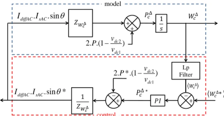
From (23) and (24), it is possible to develop the block diagram representing the behavior of the M2DC energy difference as presented in the upper part of Fig. 6. Based on the model inversion principle, the control loop of energy difference is performed as presented in the lower part of Fig. 6.
Fig. 6. Block diagram of energy difference loop via model inversion.
This control loop generates a reference for the product . It is necessary to distribute this
reference on the three terms constituting this product to define each variable: , and . To do so, the criteria defined in [12] to minimize the AC currents in the M2DC is used. It is based on a very simple idea: minimizing the AC current supposes to maximize the AC component of the modulated voltages. Let’s define the references for these voltages as:
(25) (26) From [12], to minimize the AC currents in the M2DC, the condition on the AC voltage magnitude is:
(27) In the sequel, a link is established between the condition (27) and the generation of the three references , 𝑠 and This supposes to use a steady-state model on the AC component. For doing so, complex phasor variables can be used.
Let’s define:
(28) Let’s also define the references for and :
1 2 * 1 2 ( dc ) dc v P v 𝑠 1 2 1 2 ( dc ) dc v P v diffDC
i
11
2
v
dc Lp Filter 12
v
dc * model control diffDCi
𝑠 2 1 2. .(1 dc ) dc v P v . .sin diffAC sAC I I Lp Filter model control 2 1 (1 2. *. dc ) dc v P v . .sin * diffAC sAC I I (29) (30) The associated complex variables are:
(31)
It is also possible to associate some complex values with the AC current references:
(32) The complex equations between these different variables are
used to deduce some properties.
2) Criteria to define
In a first stage, is calculated. considering (12) and (13) on only the AC component in steady state and neglecting the losses :
𝜔
𝜔 (33)
Hence, it can be considered that = .
Fig. 7 shows a phasor representation of AC M2DC voltages and currents.
Fig. 7. Phasor diagram of AC decoupled M2DC voltages and currents.
Due to equations (34), it can be considered that and are linked with the modulated voltages , :
(34)
Fig. 8 shows a phasor representation of AC voltages in the M2DC. Based on the property of the medians, as and
are equals, the angle is necessarily equal to whatever the value of .
Fig. 8. Phasor diagram of the AC M2DC voltages.
As presented before, is equal to . In consequence, the
angle is also equal to .
3) Criteria to define the ratio between and
When the angle is chosen, the value and has
to be defined. As in the previous step, some considerations have to be done on the voltages , before coming back to the currents.
Firstly (23) can to be reformulated with the modulated voltages , (35) [12].
(35)
In steady state, the variation of the energy difference must be null during a period Tfor a quasi-static analysis.
From these assumptions, the angle
can be determined (36): ²(36) Knowing the angle , it is then possible to determine a reference for and voltages through the following relationships based on the projections of and in
the Fig. 8.
² ² (37)
² ² (38)
At this point, it only remains to introduce in (37) and (38) the simplified impedances from (12) and (13) to determine the reference values for and .
(39) (40) Equations(37) to (40) leads to:
(41) The general architecture of the energy difference control is synthesized in Fig. 9. * diffAC
I
*
* sACI
*2 *
V
diffAC *2 *
V
sAC *2
V
ϕ* * mlACV
* muACV
* V
* mlACV
* mlACV
*2 *
V
diffAC *2 *
V
sACFig. 9. Architecture of the M2DC energy difference control.
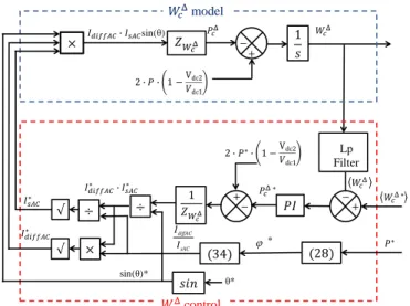
Based on these elements, the global M2DC energy control scheme is synthesized in Fig. 10. It can be noticed the closed loop controls on the energy sum and the energy difference associated with the closed loop control of the current described in section IV. It can be said that the proposed control in this paper merges two mains properties: the control of all the states variables of the system in the same time as the minimization of the AC current. Indeed, the specific way to generate the AC components of the differential currents guaranty a maximization of the AC components of the modulated voltage so a minimization of the internal AC currents.
Fig. 10. Global M2DC energy control scheme.
VI. SIMULATION PARAMETERS AND RESULTS
The control strategy has been implemented in Matlab-Simulink® software using the SimPowerSystem Toolbox. The
simulation results are given for a M2DC converter test case with three legs and a rated power equal to 600MW (200MW by leg). The system parameters are synthesized in Table I. Fig. 11 and Fig. 12 show some simulation results.
t=0.005s: power ramp (slope: 50 pu/s) from 0 to PN,
t = 40ms power ramp (slope: 50 pu/s) from PN to - PN to
show the directionality of the power through the converter,
t = 80ms, the converter is maintained at - PN. TABLEI
SIMULATIONPARAMETERS
Parameter Value Parameter Value
1 dc
v
320 kVl
4mH 2 dcv
250 kVl
s 70mH
700π rad/sr
4mΩ totC
25 µFr
s 50mΩ*
*
Ctotu Ctotlv
v
v
dc1 _ max _ max muAC mlACV
V
70 kV*
2
P
N 600 MWAll PI controllers have been designed based on pole placement design. The response times and of the different loops are defined in Table II.
TABLEII
SIMULATIONPARAMETERS
Parameter Value Parameter Value
Idiff
Tr
1 msTr
Is 1 ms WTr
100 msTr
W 100 ms I
1
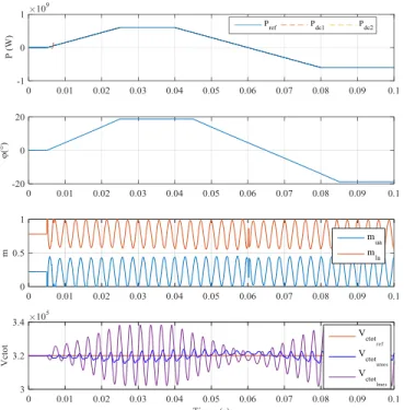
W 0.7The upper part of Fig. 11 shows the power response on both sides of the converter to P*. The input and output power measurements follow perfectly the reference which validates the control current loops. In the second part of Fig. 11, the angle is shown then the proposed control is done with the modulation of this angle. As expected with (36) and Table I values, the angle is equal to 18.85° at the rated power. The third graph shows the modulation indexes of the arms of the leg A. the AC components are close to the limits of saturation of the control (mj reaches 0 or 1 during the simulation).
The last part of this graph shows the upper and lower equivalent arm capacitor voltage . It is shown that the mean value is kept equal to 320kV. The robustness of the proposed control is finally validated. The ripple of is related to the fluctuating power generated by the AC components. The ripple amplitudes are very different between the upper and lower arms as has the same value in the upper and lower arms. It is then clear that we could reduce this value for the upper arm and optimized the M2DC design.
sin(θ) 𝑠 model control Lp Filter θ* 𝑠 * sin(θ)* diffAC sAC I I Lp Filter θ* 𝑠 * sin(θ)* diffAC sAC I I 1 2 * 1 2 ( dc ) dc v P v 1 1 2vdc Lp Filter * diffDC i 2 1 dc v sDC i (t) (t) (t) (t)
Fig. 11. M2DC simulation results with the phase shift control.
Fig. 12 presents all the M2DC current waveforms (IDC1, IDC2, , , and ) of the leg A for the same operating points.
In the first part of Fig. 12, each DC side current has no AC component, as expected and proving the good synchronization of the three phases.
Fig. 12. M2DC Currents.
, , and components at the rated power (600MW) are synthesized in table III.
TABLEIII CURRENTS VALUES AT
P
N DC value AC amplitude Peak value (AC+DC) RMS value ui
624A 1132A 1932A 1114As
i
800A 421.5A 1241A 858.8Al
i
-176A 1308A 1485A 942.4Adiff
i
312A 1196A 1508A 938ABased on table I and (41), the ratio between and must be equal to 2.98. The simulation results (2.84) is quite close. The 4.7% of difference comes from the assumption to neglect the internal resistance of inductances in the theoretical part. The current values summarized in the table III show that the converter is technologically viable using commercially available semiconductor devices.
VII. CONCLUSION
This paper has presented an equivalent average arm model for the M2DC, later used to derive a control scheme based on the lower side phase and circulating difference currents, together with the sum and the difference energy levels. The major idea proposed in this paper is focused on the full energy control generating optimal current references to minimize the internal currents magnitude. The energy sum and difference models are presented, and then the energy control is developed. Both current and energy control loops are based on the model inversion principle in order to control all the state variables. If the control of the energy sum may be considered as very similar to what is done in the MMC, the control of the energy difference presents a clear difference. Indeed, on top of controlling this energy difference with a good dynamic, it ensures the minimization of the circulating currents based on the approach proposed in [11]. Simulation results verify the good performances of the converter control. Future works will focus on the optimal design of the converter and estimation of M2DC losses and the integration of this type of converter in a Multiterminal DC grid.
REFERENCES
[1] G. P. Adam, I. A. Gowaid, S. J. Finney, D. Holliday and B. W. Williams, "Review of dc–dc converters for multi-terminal HVDC transmission networks," IET Power Electronics, vol. 9, no. 2, pp. 281-296, Oct. 2016. doi: 10.1049/iet-pel.2015.0530.
[2] J. D. Páez, D. Frey, J. Maneiro, S. Bacha and P. Dworakowski, "Overview of DC–DC Converters Dedicated to HVdc Grids," in IEEE IEEE Trans. Power Del., vol. 34, no. 1, pp. 119-128, Feb. 2019. doi: 10.1109/TPWRD.2018.2846408.
[3] B. Li, X. Zhao, D. Cheng, S. Zhang and D. Xu, "Novel Hybrid DC/DC Converter Topology for HVDC Interconnections," IEEE Trans. Power Electron., vol. 34, no. 6, pp. 5131-5146, June 2019. doi: 10.1109/TPEL.2018.2866415
[4] D. Jovcic and H. Zhang, "Dual Channel Control With DC Fault Ride Through for MMC-Based, Isolated DC/DC Converter," IEEE Trans. Power Del., vol. 32, no. 3, pp. 1574-1582, June 2017. doi: 10.1109/TPWRD.2017.2675909.
[5] S. H. Kung and G. J. Kish, "Multiport Modular Multilevel Converter for DC Systems," IEEE Trans. Power Del., vol. 34, no. 1, pp. 73-83, Feb. 2019. doi: 10.1109/TPWRD.2018.2846264.
[6] F. Gruson, F. Colas, P. Delarue, J. Freytes, X. Guillaud, S. Samimi, "Impact of different control algorithms on Modular Multilevel Converters electrical waveforms and losses Proc. 17th Eur. Conf. Power Electron. Appl. (EPE), pp. 1-10, Sept. 2015. doi: 10.1109/EPE.2015.7309115
[7] H. Saad, S. Dennetiere, J. Mahseredjian, S. Nguefeu: "Detailed and Averaged Models for a 401-Level MMC–HVDC System," IEEE Trans. Power Del., Vol. 27, no 3, pp. 1501-1508, July 2012, doi:10.1109/TPWRD.2012.2188911.
[8] A. Antonopoulos, L. Angquist, and H. P. Nee, “On dynamics and voltage control of the modular multilevel converter,” Proc. 13th Eur. Conf. Power Electron. Appl. (EPE), pp. 1-10, Sep. 2009.
[9] J. A. Ferreira, "The Multilevel Modular DC Converter," IEEE Trans. Power Electron., vol. 28, no. 10, pp. 4460-4465, Oct. 2013. doi: 10.1109/TPEL.2012.2237413
[10] H. Yang, J. Qin, S. Debnath and M. Saeedifard, "Phasor Domain Steady-State Modeling and Design of the DC–DC Modular Multilevel Converter”, IEEE Trans. Power Del., vol. 31, no. 5, pp. 2054-2063, Oct. 2016. doi: 10.1109/TPWRD.2016.2515498
[11] Y. Li, F. Gruson, P. Delarue, P. Le Moigne, "Design and control of modular multilevel DC converter (M2DC)", Proc. 19th Eur. Conf. Power Electron.
Appl. (EPE), pp. 1-10, Sep. 2017. doi:
10.23919/EPE17ECCEEurope.2017.8099108.
[12] H. Yang and M. Saeedifard, "A Capacitor Voltage Balancing Strategy With Minimized AC Circulating Current for the DC–DC Modular Multilevel Converter," IEEE Trans. Ind. Electron., vol. 64, no. 2, pp. 956-965, Feb. 2017. doi: 10.1109/TIE.2016.2613059.
[13] M. Hagiwara, R. Maeda and H. Akagi, "Control and Analysis of the Modular Multilevel Cascade Converter Based on Double-Star Chopper-Cells (MMCC-DSCC)," IEEE Trans. Power Electron., vol. 26, no. 6, pp. 1649-1658, June 2011. doi: 10.1109/TPEL.2010.2089065.
[14] J. Freytes et al., "Improving small-signal stability of an MMC with CCSC by control of the internally stored energy", IEEE Trans. Power Del., vol. 33, no. 1, pp. 429-439, Feb. 2018. doi: 10.1109/TPWRD.2017.2725579. [15] P. Delarue, F. Gruson, X. Guillaud, "Energetic macroscopic representation
and inversion based control of a modular multilevel converter", Proc. 15th Eur. Conf. Power Electron. Appl. (EPE), pp. 1-10, Sep. 2013. doi: 10.1109/EPE.2013.6631859.
François Gruson (M’14) received the Ph.D.
degree in electrical engineering from the Ecole Centrale de Lille, Lille, in 2010. Since 2011, he has been working as Associate Professor at Arts and Metiers ParisTech in the Laboratoire d’Electrotechnique et d’Electronique de Puissance of Lille (L2EP), Lille, France. His research interests include power electronic converter and power quality for distribution and transmission grid applications and especially for HVDC transmission grid.
Yafang Li received the M.S. (2015) in
electrical engineering from Grenoble Institute of Technology, France and the Ph.D. (2019) in electrical engineering from Ecole Centrale de Lille, France. Her research interests include high voltage and power DC/DC converter.
Philippe Delarue received the Ph.D.
degree from the University of Sciences and Technologies of Lille, Villeneuve d’Ascq, France, in 1989. Since 1991, he has been an Assistant Professor with the Polytech’Lille and the Laboratory of Electrotechnics and Power Electronics, Ecole Polytechnique, Universitaire de Lille, Villeneuve d’Ascq. His main research interests include power electronics and multimachine systems.
Philippe Le Moigne (M’93) received the
Engineering degree from the Institut Industriel du Nord, Lille, France, in 1986 and the Ph.D. degree in electrical engineering from the University of Lille, in 1990. He is currently a Professor with the Laboratoire d’Electrotechnique et d’Electronique de Puissance, Ecole Centrale de Lille, where he is also the Head of the Power Electronics Department. His major fields of interest include hard switched power converters and supercapacitors, especially the control of multilevel and matrix topologies for medium- and high-power applications with the aim of high power quality and high efficiency.
Frédéric Colas was born in Lille,
France, on October 17, 1980. He received a PhD in control system in 2007 from Ecole Centrale de Lille (France). Frédéric Colas is a member of the Laboratory of Electrical Engineering (L2EP) in Lille and is a Research Engineer at Arts et Métiers Paristech, 8 boulevard Louis XIV, 59046 Lille, France.
His field of interest includes the integration of dispersed generation systems in electrical grids, advanced control techniques for power system and hardware-in-the-loop simulation.
Xavier Guillaud (M’04) has been
professor in L2EP - Lille since 2002. First, he worked on the modeling and control of power electronic systems. Then, he studied the integration of distributed generation and especially renewable energy in power systems. Nowadays, he is studying the high voltage power electronic converters in transmission system. He is leading the development of an experimental facility composed of actual power electronic converters interacting with virtual grids modelled in real-time simulator. He is involved on several projects about power electronic on the grid within European projects and different projects with French companies. He is member of the Technical Program Committee of Power System Computation Conference (PSCC) and associated editor of Sustainable Energy, Grids and Networks (SEGAN).