IMPROVING THE SEISMIC RESPONSE OF TALL BRACED STEEL FRAMES WITH SEGMENTAL ELASTIC SPINE
LIANG CHEN
DÉPARTEMENT DES GÉNIES CIVIL, GÉOLOGIQUE ET DES MINES ÉCOLE POLYTECHNIQUE DE MONTRÉAL
THÈSE PRÉSENTÉE EN VUE DE L’OBTENTION DU DIPLÔME DE PHILOSOPHIAE DOCTOR
(GÉNIE CIVIL) SEPTEMBRE 2018
ÉCOLE POLYTECHNIQUE DE MONTRÉAL
Cette thèse intitulée :
IMPROVING THE SEISMIC RESPONSE OF TALL BRACED STEEL FRAMES WITH SEGMENTAL ELASTIC SPINE
présentée par : CHEN Liang
en vue de l’obtention du diplôme de: Philosophiae Doctor a été dûment acceptée par le jury d’examen constitué de :
M. LÉGER Pierre, Ph. D., président
M. TREMBLAY Robert, Ph. D., membre et directeur de recherche Mme TIRCA Lucia, Ph. D., membre et codirectrice de recherche M. BOUAANANI Najib, Ph. D., membre
ACKNOWLEDGEMENTS
This thesis not only represents my work at the keyboard, but is also a milestone in my years of searching for the best seismic resistant systems. Research is never an easy task, I am glad that I have met so many great people along the way.
First and foremost, I would like to express my sincere gratitude towards my supervisor Prof. Robert Tremblay. He has been supportive since the first day I began working with him. He always encourages me to take on harder tasks and uses his immense knowledge and wisdom to guide me through the journey. He helped me come up with the thesis topic and supported me for all the years I spent on this topic. I appreciate all his contributions of time, ideas and funding to make my Ph.D. experience stimulating.
I also would like to thank my co-supervisor Prof. Lucia Tirca. She has been my supervisor since I started my graduate study. Her enthusiasm for research work has been an inspiration to me for over eight years. She is the nicest person I know, and I am really thankful for all the support she provided.
Many people have helped and taught me immensely at Ecole Polytechnique de Montreal. The technicians and researchers at structural lab: Martin Leclerc. Romain Siguier, Xavier Willem. Thanks to them for their kind assistance during the time I worked in the lab. I would also like to thank Yasaman Minouei, Ali Imanpour, Morteza Dehghani, Paul Mottier for their kindly shared research and laboratory experience.
I am grateful to all my colleagues when I worked as an intern in SBSA Experts-conseils en structure: Jeffrey Leibgott, Evan Irvine, Alessio Bernardi. They taught me what civil engineering is about with real-life examples. I will treasure this experience all my life.
I gratefully acknowledge the funding sources that made my Ph.D. work possible. The funding was provided by the National Science Engineering Research Council and the Fonds de Recherche du Quebec – Nature et Technologies. I also want to acknowledge the funding source that provided me the valuable intern experience, the Mitacs Accelerate program.
Lastly, I would like to thank my family for all their love, encouragement and support. For my parents who raised me with a love of science and supported me in all my pursuits. And most of all
for my loving, supportive, encouraging, and patient wife Xuan Qin whose faithful support during this rugged but fruitful journey is much appreciated. Love you.
Liang Chen
Ecole Polytechnique de Montreal August 2018
RÉSUMÉ
Les cadres contreventés en acier conventionnels sont largement utilisés comme systèmes de résistance à la force latérale contre les tremblements de terre pour leur réponse sismique légère et ductile. Cependant, de nombreuses études ont prouvé que les cadres à contreventement concentrique (CBF) et les cadres à contreventement excentré (EBF) sont enclins à un mécanisme d'effondrement à étage mou. Les dommages sont susceptibles de se concentrer sur un seul étage après le début de la production de l'élément de dissipation d'énergie (entretoise ou maillon) à l'étage correspondant.
De nombreuses configurations structurelles innovantes ont été proposées au cours des dernières décennies pour empêcher l'effondrement des cadres à ossature en acier, le cadre à contreventement excentré (TBF) étant l'un d'entre eux. TBF est développé basé sur EBF conventionnel. Des liens élastiques sont ajoutés pour attacher les liens ductiles des étages adjacents. Ainsi, les liens, les colonnes, le faisceau à l'extérieur des liens, et les entretoises forment une colonne élastique continue le long de la hauteur du bâtiment, pour forcer un mécanisme d'effondrement global. Bien que des performances sismiques remarquables soient obtenues avec les TBF, les demandes de force dans les éléments structurels croissent exponentiellement avec le nombre croissant d'étages dans la structure. En conséquence, il devient rentable de concevoir et de construire un tel système dans des bâtiments plus hauts.
Un nouveau type de configuration structurelle appelé structures contreventées de treillis élastique segmentés (SESBF) est proposé et étudié dans cette recherche. Ce système évolue à partir des EBF et TBF conventionnels tout en combinant les avantages des deux systèmes, à savoir le poids léger et la demande sismique réduite des EBF et la performance sismique améliorée des TBF. Un cadre entièrement attelé excentré est divisé en plusieurs segments le long de la hauteur du bâtiment, et les liens entre les segments sont retirés. Par conséquent, le moment fléchissant de l'épine élastique continue est libéré au niveau des articulations entre les segments. Une série d'analyses numériques est menée pour examiner la réponse sismique du système de segment rachidien élastique avec EBF et TBF conventionnels comme références. Il est prouvé que le système d'élasticité segmentaire élastique, s'il est conçu correctement, peut atteindre une performance sismique optimale sans augmentation significative en termes de coût. L'accent d'un design approprié est mis en avant car
une tendance du développement de segment mou est prévisible pour les bâtiments élevés dans des conditions de charge sismique extrêmes.
Afin de développer une méthode de conception pratique et robuste, une combinaison d'approches analytique et numérique est employée. Un groupe de SESBFs allant de 8 à 24 étages avec différentes longueurs de segments est conçu avec les résultats obtenus à partir d'analyses de l'historique de la réponse temporelle non linéaire. La demande en forces de chaque élément structural et la réponse sismique des structures sont étudiées à la fois dans le domaine temporel et dans le domaine fréquentiel. Une analyse modale est également effectuée pour ces structures. On observe que la réponse post-élastique où les composantes principales se sont plastifiées à un effet significatif sur la demande de force maximale des membres des épines élastiques. Avec ces résultats, une méthode de conception qui utilise la technique de superposition modale est proposée et vérifiée numériquement pour déterminer la demande de force des membres structurels dans les fermes élastiques avec des sections de liaison données. Une analyse de spectre de réponse modifiée est utilisée pour prédire la demande de force des éléments élastiques en raison de modes de vibration plus élevés.
Pour aider à déterminer la longueur et la configuration optimales des segments, une procédure complète pour la conception préliminaire et l'optimisation du SESBF est également développée. Cette procédure est basée sur un modèle numérique simplifié. Ce modèle regroupe la rigidité de cisaillement et la rigidité à la flexion de chaque segment dans les SESBFs en un ressort de cisaillement et une colonne élastique. Des équations et des procédures pour estimer ces raideurs sont également développées. Ainsi, les concepteurs peuvent effectuer à la fois l'analyse de spectre et l'analyse de l'historique temporel pour une configuration particulière d'intérêt, sans connaître les propriétés exactes de la trame. Une fois qu'un niveau de performance cible est sélectionné, une configuration optimale peut être déterminée à l'aide de quelques itérations de l'analyse de l'historique temporel. Cette procédure est vérifiée numériquement, une bonne corrélation entre le modèle simplifié et le modèle complet est atteinte. L'application de la procédure proposée est démontrée pour un SESBF de 24 étages.
Un programme d'essais expérimental est également développé à l'aide du simulateur de tremblement de terre du Laboratoire d'ingénierie structurelle de la Polytechnique de Montréal. Un
cadre à chevrons de 8 étages conçu sur la base du NBCC de 1980 et un SESBF de 8 étages à deux segments conçus avec les exigences de force résultant d'une analyse de l'historique temporel non linéaire sont conçus et réduits à 30%. Le cadre mis à l'échelle et le cadre original sont analysés par analyse numérique pour valider le modèle mis à l'échelle. Des tests de mise en forme en temps réel seront effectués sur les trames mises à l'échelle pour confirmer les prédictions obtenues à partir de l'analyse numérique et valider l'adéquation de la procédure de conception proposée et la réponse sismique prédite du SESBF.
ABSTRACT
Conventional steel braced frames are widely used as lateral force resisting systems against earthquakes for their light weight and ductile seismic response. However, numerous studies have proven that both concentrically braced frames (CBFs) and eccentrically braced frames (EBFs) are prone to soft-storey collapse mechanism. Damage is likely to concentrate on a single storey after the energy dissipating component (brace or link) at corresponding storey starts to yield.
Many innovative structural configurations were proposed in the past decades to prevent the soft-storey collapse of steel braced frames, tied eccentrically braced frame (TBF) being one of them. TBF is developed based on conventional EBF. Elastic ties are added to tie the ductile links of adjacent storeys together. Thus, the ties, the columns, the beam outside of links, and the braces form a continuous elastic spine along the building height, to force a global collapse mechanism. Although remarkable seismic performance is achieved with the TBFs, the force demands in structural members grow exponentially with the increasing number of storeys in the structure. As a result, it becomes cost-inefficient to design and construct such system in taller buildings. A new type of structural configuration named braced frame with segmental elastic spine (SESBF) is proposed and studied in this research. This system evolves from conventional EBF and TBF while combines the advantages of both systems, i.e. the light weight and reduced seismic demand of the EBFs and the enhanced seismic performance of the TBFs. A fully tied eccentrically braced frame is divided into several segments along the building height, and the ties between segments are taken out. Consequently, the bending moment of the continuous elastic spine is released at the joints between segments. A series of numerical analyses are conducted to examine the seismic response of the segmental elastic spine system with conventional EBF and TBF as references. It is proven that the segmental elastic spine system, if designed properly, can achieve optimum seismic performance without a significant increase in terms of cost. The emphasize of a proper design is brought up because a tendency of soft-segment development is foreseeable for tall buildings under extreme seismic loading conditions.
To develop a practical and robust design method, a combination of analytical and numerical approach is employed. A group of SESBFs ranging from 8- to 24-storey SESBFs with various length of segments is designed with the results obtained from nonlinear time history analyses. The
forces demand of each structural member and the seismic response of the structures are studied both in time domain and frequency domain. Modal analysis is also performed for these structures. It is observed that the post elastic response where the main yielding components that are yielded has a significant effect on the maximum force demands on the members of the elastic spines. With these findings, a design method that utilizes modal superposition technique is proposed and verified numerically for determining the force demand of structural members within the elastic trusses with given link sections. A modified response spectrum analysis is utilized to predict the force demand of the elastic members because of higher vibration modes.
To help determine the optimum length and configuration of the segments, a complete procedure for the preliminary design and optimization of the SESBF is also developed. This procedure is based on a simplified numerical model. This model lumps the shear stiffness and flexure stiffness of each segment in the SESBFs into one shear spring and one elastic column. Equations and procedures to estimate these stiffnesses are also developed. Thus, designers can perform both spectrum analysis and response time history analysis for a particular configuration of interest in a timely fashion without knowing the exact properties of the frame. Once a target performance level is selected, an optimum setup of SESBF can be determined through a few iterations of time history analysis. This procedure is verified numerically and good correlation between the simplified model and the full model is achieved. The application of the proposed procedure is demonstrated for a 24-storey SESBF.
An experimental test program is also developed using the earthquake simulator at the Structural Engineering Laboratory at Polytechnique de Montreal. Shake table test will be performed on a 30% scaled model of an 8-storey chevron braced frame designed based on 1980 NBCC to confirm the deficiencies identified by nonlinear dynamic analysis. The experimental program includes a second test that will be performed on an 8-storey SESBF with two-segment (SESBF-2) which is designed as retrofit solution for the existing frame. Both the scaled and the original frame are analyzed through numerical analysis to validate the scaling process. The shake table tests will confirm the accuracy of the numerical analysis used to predict the seismic response of both the existing CBF and the SESBF systems and validate the adequacy of the proposed design procedure for the SESBF system. The test will also confirm the possibility of using SESBFs as a rehabilitation scheme to retrofit existing sub-standard structures.
TABLE OF CONTENTS
ACKNOWLEDGEMENTS ... III RÉSUMÉ ... V ABSTRACT ... VIII LIST OF TABLES ...XVI LIST OF FIGURES ...XXII LIST OF SYMBOLS AND ABBREVIATIONS....XXVII LIST OF APPENDICES ...XXX
CHAPTER 1 INTRODUCTION ... 1
1.1 Background ... 1
1.2 Problem definition ... 4
1.3 Objectives and Scope of the Study ... 5
1.4 Methodology ... 6
1.5 Thesis structure ... 6
CHAPTER 2 LITERATURE REVIEW ... 8
2.1 Soft storey mechanism ... 8
2.2 Soft storey mechanism in concentrically braced frames ... 9
2.3 Soft storey mechanism in eccentrically braced frames ... 10
2.3.1 Discussion of seismic response of EBFs in the 1990s ... 11
2.3.2 Seismic response of Modern EBFs ... 14
2.4 Existing structural systems to prevent soft-storey mechanism ... 16
2.4.1 Zipper braced frame ... 16
2.4.3 Tied braced frame ... 29
2.4.4 Rocking frames ... 33
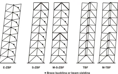
CHAPTER 3 DEVELOPMENT OF BRACED FRAME WITH SEGMENTAL ELASTIC TRUSSES SYSTEM ... 38
3.1 Understanding of soft-storey mechanism in CBFs and EBFs ... 38
3.1.1 The soft-storey mechanism in CBFs ... 38
3.1.2 The soft-storey mechanism in EBFs ... 41
3.2 Braced frames with fully tied systems ... 43
3.2.1 Elastic zipper braced frame (EZBF) ... 44
3.2.2 Suspended zipper braced frame (SZBF) ... 46
3.2.3 Tied EBF (TBF) ... 48
3.2.4 Seismic response of fully tied braced frames ... 49
3.3 Development of segmental systems with elastic trusses ... 49
3.4 Seismic response of braced frame with segmental elastic trusses ... 52
3.4.1 Typical response of braced frame with segmental elastic trusses ... 52
3.4.2 Potential improvement for a braced frame with segmental elastic trusses ... 53
3.5 Design of braced frame with segmental elastic trusses ... 55
3.5.1 Capacity design approach ... 56
3.5.2 Frequency analysis ... 57
3.5.3 Modal superposition ... 58
3.5.4 Inelastic vibration modes ... 59
3.5.5 Determination of inelastic vibration modes ... 60
3.5.6 Design of SESBFs ... 61
3.6 Optimum design of braced frame with segmental elastic trusses ... 65
3.6.1 Simplified structural model ... 66
3.6.2 Validation of the simplified model ... 68
3.7 Proposed design methodology ... 70
3.7.1 Determine the best configuration for a SESBF ... 71
3.7.2 Design the SESBF with selected configuration ... 72
3.8 Experimental test program ... 74
3.8.1 Purpose of the test program ... 74
3.8.2 Test setup ... 75
CHAPTER 4 ARTICLE 1: MODULAR TIED ECCENTRICALLY BRACED FRAMES FOR IMPROVED SEISMIC RESPONSE OF TALL BUIDLINGS ... 76
4.1 Introduction ... 76
4.2 Building and Framing Systems Studied ... 79
4.2.1 Buildings studied ... 79
4.2.2 Design of the structures ... 80
4.2.3 Design of the vertical elastic trusses ... 84
4.3 Seismic Analysis ... 86
4.3.1 Numerical Model ... 86
4.3.2 Nonlinear Static (Pushover) Analysis ... 89
4.3.3 Selection and Scaling of Ground Motions ... 91
4.3.4 Analysis Results for the Structures ... 92
4.3.5 Residual drift responses for the 8-storey and 16-storey frames ... 102
4.3.6 Collapse assessment using incremental dynamic analysis (IDA) ... 104
CHAPTER 5 ARTICLE 2: PRACTICAL SEISMIC DESIGN PROCEDURE FOR STEEL
BRACED FRAMES WITH SEGMENTAL ELASTIC SPINES ... 113
5.1 Introduction ... 113
5.2 Analysis and Design Methods ... 117
5.2.1 Modal superposition method ... 117
5.2.2 Proposed design procedure ... 126
5.3 Case Study ... 127
5.3.1 Buildings studied ... 127
5.3.2 SESBF Design ... 128
5.3.3 Validation of the method through nonlinear dynamic analysis ... 138
5.4 Conclusions ... 156
CHAPTER 6 ARTICLE 3: DETERMINATION OF OPTIMUM CONFIGURATIONS FOR STEEL BRACED FRAMES WITH SEGMENTAL ELASTIC SPINES ... 164
6.1 Introduction ... 165
6.2 Proposed Methodology ... 167
6.2.1 Simplified structural model (SM) ... 167
6.2.2 Stiffness and strength properties ... 169
6.3 Detailed Procedure ... 173
6.3.1 Selection of a truss segment configuration ... 174
6.3.2 Determining initial SM properties using ESFP ... 174
6.3.3 Construct the SM model and perform RSA ... 177
6.3.4 Verification of the fundamental period and seismic drifts ... 178
6.3.5 Verification of the wind drifts ... 179
6.3.7 Verification of NHLRA results ... 179
6.3.8 Comparison with other truss segment configurations ... 180
6.3.9 Final Design ... 180 6.4 Design Example ... 180 6.4.1 Buildings studied ... 181 6.4.2 Preliminary design ... 182 6.4.3 NLRHA ... 184 6.4.4 Final Design ... 190 6.5 Conclusion ... 195
CHAPTER 7 EXPERIMENTAL TEST PROGRAM ... 200
7.1 Introduction ... 200
7.2 Test program ... 200
7.2.1 Overview ... 200
7.2.2 Design of original frames ... 201
7.2.3 Scaling of testing frames ... 208
7.2.4 Selection of ground motions ... 212
7.3 Numerical models and simulation results ... 213
7.3.1 Modeling details ... 213
7.3.2 Modeling of connections ... 215
7.4 Expected results ... 216
7.4.1 Possible failure modes: ... 216
7.4.2 Seismic response of the scaled models ... 218
CHAPTER 9 CONCLUSIONS AND RECOMMENDATIONS... 223
9.1 General ... 223
9.2 Summary and conclusions ... 224
9.3 Recommendations for future studies ... 227
BIBLIOGRAPHY ... 229
LIST OF TABLES
Table 3-1: Calibration of ductile link model ... 42
Table 3-2 Suggested fundamental periods by the code and fundamental periods obtained from dynamic analysis ... 62
Table 3-3 CMR of structural systems ... 65
Table 4-1 Building periods, steel tonnage and maximum seismic base shears (/frame). ... 83
Table 4-2 Test results used for the calibration of link beam elements ... 88
Table 4-3 Drift concentration factors (DCF) from NSA for the 8- and 16-storey frames. ... 91
Table 4-4 Values of response parameters for the 8-storey and 16-storey braced frames. ... 93
Table 4-5 DCF values for the 8-storey and 16-storey braced frames. ... 94
Table 4-6 Evaluation of collapse safety of the 16-storey buildings according to FEMA P695 ... 106
Table 5-1 Elastic and inelastic modal properties for the 8-storey SESBF-1 configuration ... 121
Table 5-2 Design spectrum ordinates for site class C in Vancouver, BC ... 129
Table 5-3 Parameters used to calculate the design base shear ... 129
Table 5-4 Periods (s) of the elastic and inelastic vibration modes of the 8-storey SESBFs ... 130
Table 5-5 Periods (s) of the elastic and inelastic vibration modes of the 16-storey SESBFs ... 131
Table 6-1 Design spectrum ordinates for Site Class C, Vancouver ... 183
Table 6-2 selected ground motions ... 186
Table 6-3 Characteristics and storey drift response of the SESBF configurations ... 194
Table 7-1 Periods of structures (sec) ... 205
Table 7-2 Member sections of selected CBF ... 206
Table 7-3 Member sections for 8-storey SESBF with 2 segments ... 207
LIST OF FIGURES
Figure 1-1: Typical soft-storey response of CBFs ... 1
Figure 1-2: U.S. -Japan EBF Test Structure (Popov, Ricles, & Kasai, 1992) ... 2
Figure 1-3: Braced frame systems proposed to prevent soft-storey response ... 3
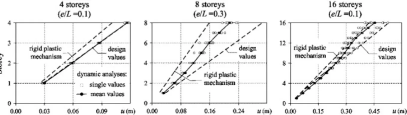
Figure 1-4: 8-storey segmental braced frame with 2 segments: a) segmental ZBF; b) segmental TBF ... 5
Figure 2-1: Maximum response and schematic diagram of Olive View Medical Center under 1971 San Fernando earthquake (Mahin, Bertero, Chopra, & Collins, 1976) ... 8
Figure 2-2: Braced hysteresis loop and different zones (Chen, 2011) ... 9
Figure 2-3 Chevron braced frame configuration and its failure mechanism (Bruneau et al. 2005) ... 10
Figure 2-4: Typical configuration and yielding mechanism of EBFs ... 10
Figure 2-5: Response of six-storey EBF (Popov, 1992) ... 12
Figure 2-6: Seismic response of thirteen-storey EBF (Popov, Ricles, & Kasai, 1992) ... 13
Figure 2-7: Zipper braced frame configuration and its yielding mechanism (Chen, 2011) ... 17
Figure 2-8: Behaviour of zipper braced frame system with weak zipper column (Tirca & Tremblay, 2004): a) zipper yields in tension; b) zipper buckles in compression ... 17
Figure 2-9: Mechanisms and lateral load distributions adopted for design with brace buckling initiating at the: a) upper floors; b) lower floors (Tremblay & Tirca, 2003) ... 18
Figure 2-10 Computed peak axial loads in zipper columns for 4-, 8-, 12-storey buildings (Tirca & Tramblay, 2004) ... 19
Figure 2-11 Axial force in zipper columns obtained from nonlinear dynamic time-history analyses of 4-, 8-, 16-story buildings (Tirca & Chen, 2012) ... 20
Figure 2-12 Maximum compression and tension forces in zipper columns of 12-storey zipper frame under regular, near-field and Cascadia ground motions (Chen, 2011) ... 21
Figure 2-13: BRB with elastic truss (Tremblay & Merzouq, 2004; Tremblay & Poncet, 2007) ... 23
Figure 2-14 Elevation views of six different bracing configurations: (a) V6; (b) X6; (c) X6-3; (d) SB6-3; (e) SB6-3B; (f) SB6-3 L (Lai & Mahin, 2015) ... 24
Figure 2-15 Schematic drawing of strongback test specimen (Simpson & Mahin, 2018) ... 25
Figure 2-16 Elevation drawing of the Heinz Avenue Building (Panian, Bucci, & Janhunen, 2015) ... 26
Figure 2-17 BRBM frame elevation (Panian, Bucci, & Janhunen, 2015) ... 27
Figure 2-18 Concept of stiff rocking core rehabilitation technique (Pollino, Slovenec, Qu, & Mosqueda, 2017) ... 28
Figure 2-19 Hybrid analytical substructuring (Slovenec, Sarebanha, Pollino, Mosqueda, & Qu, 2017) ... 29
Figure 2-20: Force combinations for member design proposed by (Rossi, 2007) ... 31
Figure 2-21: Results of non-linear dynamic analysis in terms of maximum lateral displacement (Rossi, 2007) ... 32
Figure 2-22: Axial forces of braces, beam segments, ties and columns for analyzed structures (Rossi, 2007) ... 33
Figure 2-23 Rocking frame (Roke et al., 2009) ... 34
Figure 2-24 FBF with multiple BRB columns and the axial forces in the columns (Tremblay et al. 2004) ... 36
Figure 2-25 Rocking frame with load reducing fuses (Wiebe et al., 2012) ... 37
Figure 2-26 Shear force envelopes and storey drift distributions (Wiebe et al., 2012) ... 37
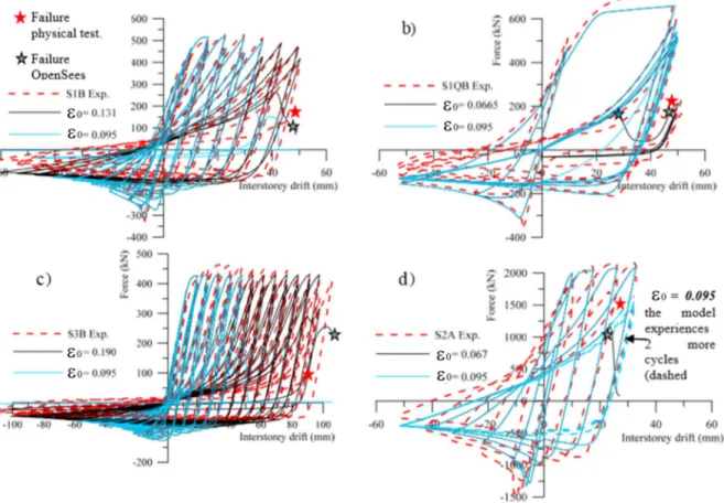
Figure 3-1: Comparisons between simulated brace response and experimental test results ... 39
Figure 3-2: Interstorey drift profiles 4-, 8- and 12-storey CBF buildings under subduction and crustal record sets (Tirca, Chen, & Tremblay, 2015) ... 40
Figure 3-3: a) Replaceable link beams with end plate connections and proposed ties to link connection detail; b) Calibration of the numerical hysteretic link model in OpenSees (Chapter 4) ... 41 Figure 3-4: Ductile link OpenSees model ... 41 Figure 3-5: Result of time-history analyses for 8- and 16-storey EBFs (Chapter 4) ... 43 Figure 3-6: Structural configurations and their failure mechanisms: a) elastic zipper frame; b)
suspended zipper frame; c) TBF ... 44 Figure 3-7: Expected global yielding mechanisms for the framing systems studied ... 46 Figure 3-8: Brace or link induced forces for the design of: a) Exterior columns in ZBFs, b) Zipper
columns in E-ZBFs; c) Zipper columns in S-ZBFs; d) Hat truss and exterior column in S-ZBF; e) Zipper column and hat trusses in M-S-ZBF; and f) Exterior column in TBF ... 46 Figure 3-9: Interstorey drift profile for 8-storey EZBF, SZBF and TBF ... 49 Figure 3-10: Seismic response of 16-storey EZBF, SZBF and TBF ... 50 Figure 3-11: Structural configuration and yielding mechanisms of segmental SZBF and segmental
TBF ... 51 Figure 3-12: Seismic response of segmental SZBF and segmental TBF ... 52 Figure 3-13: Seismic response of 8-storey EBF, TBF and SESBF (2 segments) (Chapter 4) ... 53 Figure 3-14: Structural configurations for SESBFs with energy dissipative devices (EDs)
(Tremblay et al, 2014) ... 54 Figure 3-15: Storey drift profile of SESBFs with dissipative devices (Tremblay et al, 2014) ... 55 Figure 3-16: Snapshots of forces in main structural members obtained from time-history analysis ... 57 Figure 3-17: Power spectral of axial forces in 1st floor braces ... 58 Figure 3-18: Elastic and inelastic vibration modes of the 16-storey braced frame with segmental
Figure 3-19 Spectrum of scaled ground motions ... 62
Figure 3-20 IDA curves of 8-, 9- and 10-SESBFs ... 63
Figure 3-21 IDA curves of 12-, 15- and 16-SESBFs ... 64
Figure 3-22 a) Conventional EBF; b) Simplified model ... 66
Figure 3-23: 8-storey 2- segments SESBF and spring-mass models: a) SESBF; b) shear-spring model; c) rotational spring model; d) proposed model ... 68
Figure 3-24: Comparison of pushover analysis results between discrete model and shear spring model ... 69
Figure 3-25: a) structural model; b) Comparison of shapes of inelastic vibration modes; c) Comparison of roof deflection from time-history analysis ... 70
Figure 3-26: Design flowchart for SESBF: a) preliminary design with simplified model; b) detailed design with finite element model ... 74
Figure 4-1 Mitigation of soft-storey response in multi-storey steel braced frames: a) Concentration of inelastic deformations in EBFs; b) Tied braced frame (TBF); c) Dual-BRBF configuration; d) Higher mode response in TBF; and e) Modular tied braced frame (M-TBF). ... 79
Figure 4-2 a) Floor plan of the building studied; b) Elevation of 8-storey framing systems; c) Elevation of 16-storey framing systems. ... 80
Figure 4-3 Factored link shear forces Vf and factored link shear resistance to shear force Vr/Vf ratios for: a) 8-storey building; and b) 16-storey building. ... 84
Figure 4-4 Anticipated inelastic response of the 16-storey TBF: a) Inelastic vibration modes; b) Design forces in truss members. ... 85
Figure 4-5 Design forces in the braces, columns and tie members of the 16-storey TBF. ... 86
Figure 4-6 a) Replaceable link beams with end plate connections and proposed tie-to-link connection detail; b) Calibration of the numerical hysteretic link model in OpenSees (Test 4C). ... 87
Figure 4-7 Deformed shape of the 8-storey braced frames from NSA: a) EBF; b) TBF; and c) M-TBF. ... 90 Figure 4-8 Deformed shape of the16-storey braced frames from NSA: a) EBF; b) TBF (CL design);
c) M-TBF-1; and d) M-TBF-2. ... 90 Figure 4-9 Lateral load-displacement responses from NSA for the 8-storey and 16-storey braced
frames. ... 91 Figure 4-10 Design spectrum and 5% damped absolute acceleration spectra of the ground motion
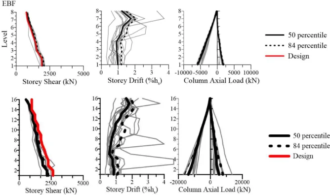
records suites: a) 8-storey frame scaled for 0.4-2.0 s; b) 16-storey frame scaled for 0.6-4.0 s ... 92 Figure 4-11 Storey shears, storey drifts, axial force in columns and tie members of the 16-storey
braced frames. ... 95 Figure 4-12 Comparison of the 84th percentile storey shears, storey drifts, and axial loads in
columns and tie members of the 16-storey braced frames. ... 96 Figure 4-13 Storey drift time histories at the 8th and 16th storeys and horizontal displacement
profiles for the 16-storey braced frames under Ground motion # 776. ... 96 Figure 4-14 Time history of the roof displacement and storey drift at first and top levels of the 16-storey braced frames and profiles of 16-storey drifts and tie axial forces under Ground motion # 776. ... 98 Figure 4-15 Time history of the roof displacement and storey drift at first and top levels of the 16-storey braced frames and profiles of 16-storey drifts and tie axial forces under Ground motion no. 767. ... 99 Figure 4-16 Storey shears, storey drifts, and axial loads in columns and tie members of the 8-storey
braced frames. ... 101 Figure 4-17 Storey shears, storey drifts, axial loads in columns and tie members of the 24-storey
braced frames. ... 102 Figure 4-18 Residual vs peak inelastic storey drifts (90th percentile) for 8-storey and 16-storey: a)
Figure 4-19 IDA curves of 16-storey frames subjected to the selected record set: a) EBF, b) TBF-CL, c) MTBF-1, d) MTBF-2 ... 105 Figure 5-1 Deflected shape of braced frames: a) conventional EBF, b) Dual-BRBF by Tremblay
(2003), c) Tied EBF (TBF) by Martini et al. (1990) and Ghersi et al. (2000), d) Modular tied EBF (M-TBF) by Liang et al. (2012). ... 117 Figure 5-2 Yielding mechanisms and lateral load patterns illustrated for the storey EBF and 8-storey SESBF-1 configuration. ... 118 Figure 5-3 Vibration modes of the 8-storey SESBF-1 configuration: a) Elastic modes; b) Inelastic
modes with reduced link stiffness (= 0.01). ... 121 Figure 5-4 Likely yielding pattern cases for a 12-storey SESBF-3 configuration. ... 124 Figure 5-5 Mode shapes and periods of 8-storey SESBF-2 configuration: a) Elastic modes; b)
Inelastic modes, Case1: links yielding in both segments; c) Inelastic modes, Case 2: links yielding in bottom segment; and d) Inelastic modes, Case 3: links yielding in second segment only (= 0.01). ... 126 Figure 5-6 Building studied: a) Plan view; b) Elevation of 8-storey configurations SESBF-1 and
SESBF-2; and c) Elevation of 16-storey configurations SESBF-2 and SESBF-4. ... 128 Figure 5-7 Calculation of the Set I member forces for the 8-storey frames assuming an inverted
triangular lateral load pattern: a) SESBF-1 configuration; b) SESBF-2 configuration. ... 133 Figure 5-8 Comparison between inverted triangular and RSA lateral load patterns used for the
calculation of Set I member forces for the 8-storey SESBF-2 configuration: a) Lateral load patterns; b) Brace axial forces; c) Tie axial forces. ... 133 Figure 5-9 Comparison between inverted triangular and RSA lateral load patterns used for the
calculation of Set I member forces for the 16-storey SESBF-2 configuration: a) Lateral load patterns; b) Brace axial forces; c) Tie axial forces. ... 134 Figure 5-10 Truncated design spectra for: a) 8-storey SESBF-1 configuration; and b) 8-storey
Figure 5-11 Set II axial forces in braces, ties and columns for cases i = 1, 2, and 3 for: a) 8-storey SESBF-2 configuration; and b) 16-storey SESBF-2 configuration. ... 136 Figure 5-12 Influence of reduced link stiffness on Set II forces of 8-storey SESBF-2 configuration. ... 136 Figure 5-13 Axial forces in braces, ties, and columns of 8-storey seismic force resisting system: a)
SESBF-1 configuration; and b) SESBF-2 configuration. ... 138 Figure 5-14 Scaled response spectra and the scenario-specific period range for each ground motion
suite for Vancouver, Site Class C: a) crustal suite, b) subduction inslab (SIS) suite, and c) subduction interface (SIF) suite ... 139 Figure 5-15 Time-history response series of 8-storey SESBF-2 configuration under ground motion
SIF3: a) Segment drifts; b) Link shear forces; c) Axial force in brace at 7th floor; d) Axial
force in tie at 7th floor; e) Axial force in brace at 3rd floor; and f) Axial force in tie at 3rd floor.
... 145 Figure 5-16 Time-history responses of 8-storey SESBF-2 configuration under ground motion C2:
a) Segment drifts; b) Link shear forces; c) Axial force in brace at 7th floor; and d) Axial force
in tie at 7th floor. ... 145
Figure 5-17 Peak values of storey shears, drifts, and axial forces in braces, columns, and ties along the height of the 8-storey SESBF-2 configuration. ... 147 Figure 5-18 Peak values of storey drifts and axial forces in braces, columns and ties for the 8-storey
SESBF-2 configuration under: a) Crustal records; b) SIS records; and c) SIF records. ... 148 Figure 5-19 Spectra and member forces from records C2, SIS1, and SIF4 for the 8-storey SESBF-2 configuration: a) Response spectra; b) Axial forces in ties; c) Axial forces in braces. .... 149 Figure 5-20 Peak values of storey drift, shears, and axial forces in braces, columns, and ties along
the height of the 8-storey SESBF-1 configuration. ... 150 Figure 5-21 Peak values of storey drifts, storey shear, and axial forces in braces, columns and ties
Figure 5-22 Peak values of storey drifts, storey shears, and axial forces in braces, columns and ties along the height of the 16-storey SESBF-4 configuration. ... 153 Figure 5-23 Shear force time-history in the links of the upper segment of SESBF-2 configuration
under C5 ground motion. ... 154 Figure 5-24 Shear force time-history developed in links of upper segment of SESBF-2
configuration under Mexico City, 1985, ground motion. ... 155 Figure 5-25 Design spectrum and response spectrum of the 1985 Mexico City earthquake (SCT,
S00E record). ... 156 Figure 5-26 Peak values and distribution of axial forces in braces, columns and ties along the height
of 16-storey SESBF-2 configuration under the 1985 Mexico City earthquake (SCT, S00E record). ... 156 Figure 6-1 Evolution of braced frame systems to mitigate the soft-storey response: a) Eccentrically
braced frames prone to damage concentration; b) TBF; c) SESBF ... 166 Figure 6-2 Typical lumped mass-spring structural model for 4-storey frame ... 168 Figure 6-3 SESBF-2 system and its deformed shape: a) Actual frame; b) Simplified model (SM) ... 169 Figure 6-4 Vertical distribution of seismic storey shears from NBCC and ASCE 7 ESFPs and RSA. ... 172 Figure 6-5 Comparison between stiffness values from preliminary design (SM) and after final
design (F): a) Flexural stiffness; and b) Shear stiffness. ... 172 Figure 6-6 Flowchart of the preliminary design process for SESBFs using the SM ... 173 Figure 6-7 Storey shear distribution pattern for the 24-storey SESBF-6 configuration. ... 177 Figure 6-8 Td/Ta for braced frames in past studies ... 178
Figure 6-9 Plan view and specified loads of the building studied. ... 181 Figure 6-10 The studied SESBF-n configurations of the 24-storey building ... 182
Figure 6-11 Storey shear distributions for the SESBF-8 configuration: a) From ESFP; b) From RSA using the SM. ... 183 Figure 6-12 Acceleration response spectra of the scaled ground motion records. ... 185 Figure 6-13 Storey drift profiles from NLRHA with the SM for the SESBF-8 configuration. ... 187 Figure 6-14 Storey drift profiles from SM NLRHA for configurations: a) SESBF-6; b) SESBF-4;
c) SESBF-3; and d) SESBF-5. ... 188 Figure 6-15 Peak storey drifts and drift concentration factor (DCF) from SM NLRHA. ... 190 Figure 6-16 Link overstrength for the SESBF-6, SESBF-4, SESBF-5 and SESBF-3 configurations. ... 191 Figure 6-17 Axial force demands in truss members for configurations: a) 6; and b) SESBF-4. ... 193 Figure 6-18 Storey drift profiles from FM NLRHA for configurations: a) SESBF-6; b) SESBF-4;
c) SESBF-3; and d) SESBF-5. ... 195 Figure 7-1 Structural laboratory (website) ... 201 Figure 7-2: Plan view and elevation view of prototype structures ... 202 Figure 7-3: Comparison between storey shear of buildings of different configurations ... 204 Figure 7-4 Storey drift profile of 8-storey chevron braced frame: a) Class C site; b) Class E site ... 206 Figure 7-5 Drawing of the composite beam ... 210 Figure 7-6: ABAQUS model of the scaled beam ... 211 Figure 7-7 Detail of the link assembly ... 212 Figure 7-8: Ground motion scaling ... 212 Figure 7-9 Spectrum of scaled ground motion records ... 213 Figure 7-10: Result of column analysis ... 214 Figure 7-11: Modeling of connections ... 215
Figure 7-12: Deformed shape ... 217 Figure 7-13 Storey drift profile of the scaled 8-storey CBF ... 218 Figure 7-14 Storey drift profile of the scaled 8-storey SESBF-2 ... 219 Figure 7-15 Axial forces of ties and braces ... 220
LIST OF SYMBOLS AND ABBREVIATIONS
Symbols
A cross-sectional area of section Ag Brace cross-sectional area
Cx Lateral force distribution coefficient
Cu Probable compressional resistance
C’u Probable post-buckling resistance
d Depth of section
E Young’s modulus
Fa Acceleration-based site coefficient
Fv Velocity-based site coefficient
Fy Yielding stress of steel
hn Total height of the structure
hi Height of the ith storey in a structure
I Moment of inertia
IE Earthquake importance factor of the structure
P column axial load for P-Δ effect calculation
r Radius of gyration
rg Force demand in members due to gravity load
rI Force demand in members due to Set I modes effect
rII Force demand in members due to Set II modes effect
Rd Ductility related force modification factor
Sa Spectrum acceleration
Ta Fundamental period of vibration of the structure
Vd Storey shear obtained by dynamic spectrum analysis
Vdesign Design storey shear
Vstatic Storey shear obtained with static equivalent method
W Seismic weight
φ Resistance factor
Abbreviations
2D 2-Dimensional
AISC American Institute of Steel Construction ASCE American Society of Civil Engineers
BF Braced frame
BRB Buckling restrained frame CBF Concentrically braced frame CSA Canadian Standards Association DCF Damage concentration factor EBF Eccentrically braced frame ED Energy dissipating devices HSS Hollow Square Section IDA Incremental dynamic analysis MD Moderately ductile
NBCC National Building Code of Canada NLRHA Nonlinear response history analysis OpenSees Open system for earthquake engineering TBF Tied braced frame
ESFP Equivalent static force procedure
SESBF Braced frame with segmental elastic spines SRC Stiff rocking core
SZBF Suspended zipper frame UHS Uniform hazard spectrum ZBF Zipper braced frame
LIST OF APPENDICES
CHAPTER 1
INTRODUCTION
1.1 Background
Steel braced frames are considered as one of the most efficient, economical and versatile structural systems against earthquake excitations. However, most conventional steel braced systems do not exhibit satisfactory performance when subjected to large earthquake forces primarily due to the concentration of deformations in a single storey which leads to premature dynamic instability of the structure. Both concentrically braced frames (CBFs) and eccentrically braced frames (EBFs), median- to high-rise, are prone to this so-called soft-storey collapse mechanism. This collapse mechanism of steel braced frames is studied extensively in the past decades.
In CBFs, input energy is designed to be dissipated through inelastic behaviour of braces, such as yielding and buckling. Due to the lack of ability of conventional CBFs to redistribute the inelastic demand over the building height, brace inelastic action often creates a soft-storey in terms of both stiffness and strength in the structure and leads to a concentration of deformation and eventually collapse of the structure as shown in Figure 1-1.
Figure 1-1: Typical soft-storey response of CBFs
In EBFs, links act as the primary energy dissipating components, and they are generally considered preferable given their substantial energy dissipating capacity and symmetric hysteretic loops. However, the yielding of link members may still create a soft storey in the structure due to the low post yielding stiffness as shown in Figure 1-2.
Figure 1-2: U.S. -Japan EBF Test Structure (Popov, Ricles, & Kasai, 1992)
During the last decades, to mitigate the soft storey response of high-rise braced frames, the braced frame system has evolved from classical CBFs and EBFs toward more complex systems such as zipper braced frames (ZBFs), tied eccentrically braced frames (TBFs), dual braced frames (DBFs), rocking braced frames (RBFs), and others.
Figure 1-3 shows the aforementioned structural systems and their global yielding mechanisms. In the ZBF system, the addition of zipper columns aims to utilize braces and beams at all storeys during an earthquake event to spread energy dissipation over the entire height of the structure. Better performance is observed when the zipper columns are specifically designed to remain elastic (EZF in Figure 1-3). In the S-ZBF configuration, an elastic hat truss is introduced at the top level. All unbalanced vertical components of the brace forces are collected in the zipper columns up to the roof level and distributed to the edge columns through the braces of the elastic truss. This configuration aims to avoid a full-height inelastic mechanism with loss of lateral strength after buckling of the compression braces.
In TBF systems, vertical ties are added to the conventional EBFs to tie together the ends of all ductile links in order to engage all the links when yielding initiates from one of them. Similar to ZBF, when the ties are designed to remain elastic, the global yielding mechanism is naturally achieved. From a different perspective, the TBFs can also be considered as two elastic brace sub-trusses connected by energy dissipating links, where the sub-sub-trusses act as a vertical spine to the structure to prevent soft-storey formation.
Figure 1-3: Braced frame systems proposed to prevent soft-storey response
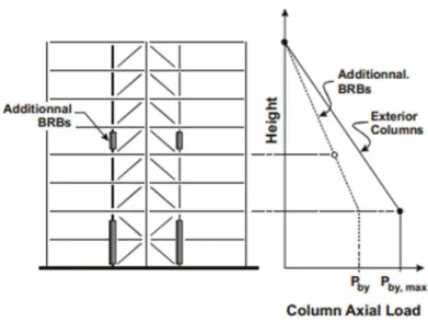
In DBFs, the structural system consists of one elastic vertical brace sub-truss and Buckling Restrained Braces (BRBs) or conventional bracing members on the other side. Input energy is dissipated through yielding of BRBs or braces while vertical continuity of the system is kept by the elastic truss(es). In rocking systems (RBFs), the frame is designed to allow uplift from its support at the base-of-column to foundation interface under strong earthquake excitations. The soft-storey formation is prevented because all structure members are expected to remain elastic during the entire earthquake event. Energy dissipation of RBFs is achieved by introducing hysteretic or viscous energy dissipating devices that are activated upon base rocking.
Most of the structural systems developed to eliminate the soft-storey collapse mechanism introduce a vertical truss or column to the original system. The truss or column is designed strong
enough to remain elastic while forcing the directly connected dissipating members on different floors to act simultaneously. This type of structure systems is categorized as the “Strongback” system.
1.2 Problem definition
Current solutions for soft-storey failure mechanism prevention utilize a full elastic back-bone/link system that attracts tremendous forces when the number of storeys increases. The large sections required to build such system make it less economical and sometimes impossible to construct. Without such systems, however, there are no viable ways to stop damage concentration in a ductile framing system, especially in medium to high seismicity regions.
Previous work also showed that partially relaxing the constraint on lateral deformation could reduce the force demand in the structure while maintaining adequate seismic performance. For instance, this is the case when allowing rocking to occur at several locations along the building height. Member forces due to overturning moments produced by higher vibration modes can then be controlled along the building height.
In this research, this approach will be examined further by introducing the concept of segmental braced frames. In this configuration, the braced frames are broken into vertical modules that extend over a number of storeys along the building height so that some flexibility is introduced in the system when deforming in the inelastic range. In each segment, soft-storey response is prevented by means of elastic truss or vertical ties, but overall frame deformation can take place at the junctions between the modules. This concept is particularly suitable for the ZBF, TBF and DBF systems. An example is given in Figure 1-4 for an 8-storey TBF. As shown, 4-storey segments are used with the ties being interrupted between each of the segment. Very limited data exits on the seismic performance of such segmental braced frame systems and no design provisions have been proposed yet to achieve the intended seismic response.
Figure 1-4: 8-storey segmental braced frame with 2 segments: a) segmental ZBF; b) segmental TBF
1.3 Objectives and Scope of the Study
The ultimate goal of this doctoral research is to develop sufficient knowledge on the seismic response of the segmental braced frame structural system and propose a seismic design method for these systems. The study focuses on segmental braced frame systems adopted for mid- to high-rise building structures.
In this light, the main objective of the study is four-fold:
1. Develop an efficient and economic seismic resisting system that is preventive to the soft-storey formation, which is named Segmental Elastic Spine Braced Frames (SESBFs). 2. Develop a robust and simple design methodology for such system. The proposed design
method will be tightly connected to the current Building Code Provisions to make it easy to apply in for Canadian applications.
3. Verify the newly developed system and design method with numerical analysis.
4. Develop an experimental test program to validate the proposed design method. The experimental program will include a test on a sub-standard CBF and a test on a SESBF. The objective is to confirm the deficiencies of the sub-standard CBF and verify if the newly
proposed system can be used as a seismic retrofit strategy. The test program will be conducted for buildings located in Montreal, Quebec.
1.4 Methodology
Main steps to fulfill aforementioned objectives were as follows:
1) Review the past researches. Great efforts have been devoted by various researchers trying to prevent damage concentration in braced frames. Existing structural configurations were examined and compared.
2) Based on previous comparison, innovative structural configurations were proposed. Prototype structural models were designed and built for these structural configurations. Nonlinear time-history analyses were performed with these models to evaluate and compare the benefits of the systems and identify their limitations.
3) The most beneficial structural system, the SESBFs, was selected and its seismic response was studied through extensive numerically simulations.
4) A practical design method was developed and validated through extensive nonlinear time-history seismic analyses.
5) An easy-to-apply procedure was developed for the determination of the optimum configurations for SESBFs at the preliminary design stage. The method was also validated through numerical simulations.
6) An experimental program was designed to qualify the seismic performance of the SESBF system while exploring the potential of the system to be used as a retrofit strategy for seismically deficient steel braced frames.
1.5 Thesis structure
This PhD dissertation is presented in 9 chapters. It is composed of the journal articles that have been written based on the results of the doctoral research.
Chapter 1 introduces the background information of the existing problem and outlines the objectives and the main activities of the research.
Chapter 2 reviews the past studies conducted by other researchers to understand and examine the existing braced frame systems which have been proposed to prevent soft-storey formation. Past researches regarding numerical simulations are also reviewed and criticized.
Chapter 3 discusses the methodologies and approaches taken to fulfill the research objectives in detail.
Chapters 4, 5, 6 present the following three articles that have been submitted for publication in scientific journals:
1) Modular tied eccentrically braced frames for improved seismic response of tall buildings. 2) Practical seismic design procedure for steel braced frames with segmental elastic spines. 3) Determination of optimum configurations for steel braced frames with segmental elastic
spines.
Chapter 7 describes the proposed experimental program.
A general discussion regarding the research process and findings is presented in Chapter 8. Finally, Chapter 9 concludes this doctoral research and highlights the main original contributions. A list of recommendations for future research is also given in this chapter.
CHAPTER 2
LITERATURE REVIEW
This chapter presents the studies conducted in the past regarding the soft-storey mechanism in braced frames and various structural configurations that have been proposed to eliminate the formation of soft-storeys in such frames. Both the conclusions and limitations of these studies are discussed to evaluate the benefits and disadvantages of each structural system in terms of seismic performance.
2.1 Soft storey mechanism
The soft-storey phenomenon is used to describe undesired structural response under ground motion excitation when large deformation is concentrated at a single floor level. The input energy, in its nature, will search for a breakthrough point in the structure, which is usually created by sudden changes in stiffness, strength and ductility. This phenomenon was observed in numerous major earthquake events, such as 1971 San Fernando earthquake, 1989 Loma Prieta earthquake, 1994 Northridge earthquake and 1995 Kobe earthquake. Figure 2-1 shows the deformation and the deformed shape of Olive View Medical Center during 1971 San Fernando earthquake.
Figure 2-1: Maximum response and schematic diagram of Olive View Medical Center under 1971 San Fernando earthquake (Mahin, Bertero, Chopra, & Collins, 1976)
Mahin, Bertero, Chopra, & Collins (1976) have concluded that the discontinuation of the shear walls in the bottom two storeys was the main reason, which caused the side-way collapse of the structure. Further studies (Cassis & Cornejo, 1996; Alekar, Jain, & Murty, 1997; Kanitkar & Kanitkar, 2004; Hejazi et al., 2011) also emphasized the direct relationship between structure stiffness/strength irregularities and the formation of soft-storey response.
2.2 Soft storey mechanism in concentrically braced frames
With the increasing popularity of steel frames, various steel configurations (MRFs and BFs) are also found to be prone to the soft-storey mechanism Khatib, Mahin, & Pister (1988). In this thesis, the discussion will focus mainly on the braced frames.
Braced frames are found weak against soft-storey mechanism, especially CBFs (Chen & Mahin, 2012). In conventional CBFs, energy is expected to be dissipated primarily through the inelastic actions of diagonal braces, such as buckling and yielding. The brace hysteresis response can be divided into four hysteresis zones: elastic zone, plastic zone, yielding zone and buckling zone as shown in Figure 2-2 (Chen, 2011).
Figure 2-2: Braced hysteresis loop and different zones (Chen, 2011)
Due to the unsymmetrical hysteretic behaviour of the brace, there is deterioration of the building lateral load behaviour after buckling of braces in terms of both stiffness and strength, which creates a soft-storey at the buckling location. The difference in brace compression and tension resistances results in unsymmetrical brace hysteretic response. Under cyclic loading, the brace compressive strength also progressively reduces, and the brace accumulates permanent elongation upon yielding
in tension, which further accentuates the dissymmetry in brace response and leads to progressive degradation of storey shear resistance. Typical failure mechanism of CBFs are illustrated in Figure 2-4.
Figure 2-3 Chevron braced frame configuration and its failure mechanism (Bruneau et al. 2005)
2.3 Soft storey mechanism in eccentrically braced frames
Eccentrically braced frame (EBF) has been widely used as a seismic load resisting system in North America. Conventional EBFs consist diagonal braces, beams, columns and specially designed ductile link elements. The system relies on yielding of these link beams to dissipate seismic energy. A typical configuration of a 2-storey conventional EBF is shown in Figure 2-4. The link beam can yield either in bending or in shear depending on the length of the link.
In EBFs, seismic input energy is essentially dissipated through shear and/or flexural yielding of the ductile link beam segments depending on the length of the segments. This translates into symmetrical and stable inelastic hysteresis response.
2.3.1 Discussion of seismic response of EBFs in the 1990s
Foutch (1989) presented a full-scale six-storey eccentrically braced dual frame building being tested in Large-Size Testing Facilities. The frame was designed with three-times the required capacity based on the 1979 and 1982 UBC provisions. Some of the results are shown in Figure 2-5. He pointed out that the response of the system was reasonably good due to the large capacity, and the energy was mostly dissipated by the yielding links. However, the damage was concentrated within the first three floors. The conclusion was made based on three dynamic tests that were conducted in the research program. They included an elastic test (very small drift), an inelastic test (maximum storey drift of 0.5%) and a series of three sinusoidal tests simulating the “first mode” response of the building to sinusoidal base excitation. The first two tests produced little to no damage to the structure with the largest storey drift of 0.5%. Majority of the observations were made solely based on the third test, which only excited the first mode of the structure. Even though, the structure performed poorly in terms of damage distribution.
Figure 2-5: Response of six-storey EBF (Popov, 1992)
Martini (1990) also demonstrated that EBFs are susceptible to a concentration of excessive inelastic link deformation at particular storey levels with a 13-storey model. The result is shown in Figure 2-6b. He proposed to use tie elements to connect the links vertically to force a global failure mechanism in the structure as shown in Figure 2-6c.
.
Figure 2-6: Seismic response of thirteen-storey EBF (Popov, Ricles, & Kasai, 1992) Later, Popov, Ricles, & Kasai (1992) pointed out that incorrectly designed link elements may lead to an undesired seismic response, which is the reason for the poor performance of EBFs observed in the previously mentioned tests. A design method for proportioning links was hence proposed by the authors. The method emphasized on choosing the link sections to have a uniform value for link over-strength throughout the frame height.
Several studies were carried out by Popov (1992) to examine this proposed design methodology, including redesigned EBFs that was presented by Foutch (1989) and Martini (1990) and a series of inelastic time-history analyses for 4, 6, 10 and 20-storey EBFs. He concluded that the main reason for soft storey mechanism to form in EBFs is the overly strengthened links. If all links are proportioned closely to the link shear force required by the code, EBF up to 10 storeys develops uniformly distributed inelastic link deformation over the building height. For EBFs with more than 10 storeys, if the static design forces are calibrated by elastic dynamic vibration modes, the proposed method can further improve their seismic inelastic performance.
He also emphasized that EBFs, for which the links are designed proportional to the NEHRP static design forces, are prone to the concentration of inelastic deformation. It is crucial to include 2nd
and 3rd vibration modes in determining the static story shear design forces. This opinion is widely
accepted nowadays; most design guidelines require dynamic analysis to be performed in designing taller EBFs. When evaluating the EBF designed in the paper by Martini (1990), Popov specifically pointed out that the links located on the upper storeys have much larger over-strength comparing with rest of the structure and hence caused the failure of the 13-storey EBF. He modified the design of link sections of the structure according to its elastic vibration modes combination with CQC method and obtained satisfactory results (Popov, 1992).
The results presented by Popov, Ricles, & Kasai (1992) depicted that EBF response is very sensitive to the vertical distribution of the over-strength ratio of ductile links in the structure. A 50% over-strength ratio of links at upper storeys as used in the example illustrated by Martini (1990) dramatically changed the dynamic response of the building and lead to a concentration of damage in the lower floors. Although the modified design method proposed by Popov can reduce the likelihood of soft storey formation, one has to realize that material properties may vary. Considering the material strength factor of link sections are ranging from 1.1 to 1.5 as found by Okazaki et al. (2004), the over-strength created by material variation alone could put conventional EBFs at risk. Moreover, link selection is also restricted by their availabilities. More often than not, the links at higher storeys of buildings are stronger than required to meet the maximum link rotation criteria, especially for structures having lower seismic demand.
2.3.2 Seismic response of Modern EBFs
Eccentrically braced frame (EBF) is a relatively new structural concept. The first recorded seismic event which pushed modern EBFs to the inelastic range was the Christchurch earthquake series of 2010/2011 in New Zealand.
Clifton, Nashid, Ferguson, Hodgson, & Seal (2012) summarized the performance of the EBFs during this event. In general, he concluded, the EBFs in New Zealand demonstrated excellent seismic resistance during said events. He also noted, data collected during the Christchurch earthquake event evidenced the adequacy of a capacity design procedure for EBF as a design method for members outside of ductile links. It was observed that all inelastic demand was concentrated into the active links as required by the procedure.
Although there were still limited number of cases where structure experienced more severe damage, the damage was more likely caused by poor detailing.
However, several major differences between building code in New Zealand and Canada must be realized.
1) All column connections including gravity column connections are required to be rigid according to P3404:2009 in New Zealand. In Canada, columns in braced frames are only required to be continuous for at least two storeys, and no rigid connection is required for any columns (CISC, 2016).
2) For buildings with weak ground floor such as parking lots, columns on ground floor are fixed to foundation with reinforced connections in New Zealand. Most of the structures examined belong to to this category. This connection detail greatly increased the lateral stiffness of the ground floor, thus reducing the possibility of soft-storey formation at this floor.
These differences could potentially change the response of EBFs in Canada compared with the response illustrated in Christchurch event. Firstly, all columns in EBFs are required to be rigidly connected throughout the building height, including gravity columns. Secondly, all columns, including gravity columns are fixed to the foundation in most of the structures examined. When the ground floor is used for the parking lots, reinforcement was added to ensure the rigidity of the connections. The impact of these modifications to conventional EBFs in North American is two-fold. The fixity of ground floor columns greatly increases the lateral stiffness of ground floor. All the rigidly connected columns also serve as connections between storeys to redistribute induced lateral loads.
In addition, the authors also noted that several link sections in the structure studied (Clifton, 2012) were fractured due to miss-alignment of link stiffeners and the connected braces. This finding indicates that failure of links could also happen due to construction errors, which could potentially lead to the formation of a soft-storey in a EBF without continuous columns.
2.4 Existing structural systems to prevent soft-storey mechanism
2.4.1 Zipper braced frame
For the chevron bracing configuration, Khatib, Mahin, & Pister (1988) proposed to link the braces to beam joints of adjacent storeys with zipper column to form a zipper braced frame (ZBF), with the aim of utilizing the stiffness of all beams and remaining braces against concentrated lateral force. The zipper columns are presented in the structure to transfer the unbalanced brace force produced upon brace buckling to adjacent levels, and thus, to force the braces located on those levels to buckle. As illustrated in Figure 2-7, the zipper frame mechanism is formed when all braces on half span experienced buckling, few braces of the other side experience yielding, and beams hinges are possibly developed at their mid-span. They proposed a design method and demonstrated the potential of the system for a 6-storey braced frame. The zipper braced frame (ZBF) was introduced in the Commentary of the AISC Seismic Provisions for Structural Steels (AISC, 1992) as an alternative means to improve the response of multi-storey braced frames. Afterwards, many studies regarding this structural system had been conducted. Sabelli (2001) designed and analyzed a 3- and 6-storey zipper braced frames. The zipper columns were selected to have the same section as the braces of the level below. Considering the vertical projection of the unbalanced load could not be greater than the brace capacity, the selections of zipper sections were conservative. The author concluded that the zipper braced frames has great potential to uniformly distribute the damage over the building height. However, while the analysed 3-storey zipper frame exhibited the expected response, the zipper columns in the 6-storey ZBF experienced non-linear behaviour that was amplified by the effects of higher modes (as illustrated in Figure 2-8), which raised the concern that the zipper columns may not be sufficiently strong to remain elastic throughout the ground excitations due to the effect of higher modes.
Figure 2-7: Zipper braced frame configuration and its yielding mechanism (Chen, 2011)
Figure 2-8: Behaviour of zipper braced frame system with weak zipper column (Tirca & Tremblay, 2004): a) zipper yields in tension; b) zipper buckles in compression
2.4.1.1 Elastic zipper braced frame
Tremblay & Tirca (2003) proposed a strong zipper column design procedure for the ZBF system to ensure that the zipper column will respond in the elastic range while transferring brace forces after brace buckling or yielding. This procedure suggested including higher modes effect in the zipper design by adopting a serial of lateral force distribution patterns representing the force redistribution after brace buckling. All structural members in the zipper frame, with the exception of zipper columns, are designed in accordance with the existing building code for moderate ductile
chevron braced frames. The so-designed ZBF system, labelled E-ZBF, ensures the development of a full-height zipper mechanism. Triangular lateral load patterns representing lateral inertia force occurring after brace buckling and yielding are used to predict the maximum possible forces that will be induced in the zipper columns. Several different lateral load patterns are applied upon buckling of every brace member to capture the redistributed shear force. Furthermore, two scenarios are considered depending on whether brace buckling is initiated from the top or the bottom of the frame, as shown in Figure 2-9.
Figure 2-9: Mechanisms and lateral load distributions adopted for design with brace buckling initiating at the: a) upper floors; b) lower floors (Tremblay & Tirca, 2003)
The lateral force was assumed to be at the maximum level at the bottom/top where the brace buckling first occurred. This force linearly diminished to zero at the level above/below the storey where the brace just buckled. In this respect, the lateral forces are redistributed mostly to the levels with reduced lateral stiffness due to inelastic behaviour, i.e. brace buckling. Based on this load distribution pattern, maximum compression and tension demands in the zipper columns were enveloped, and the zippers can be designed accordingly.
With the zipper columns being designed to remain elastic, the axial forces induced by the braces can be effectively transferred across the entire structure and inelastic response can be achieved over the entire structure height. Additional numerical analyses conducted for a 4-, 8- and 12- storey structures located in Victoria, B.C. (Tirca &Tremblay, 2004) under various ground motion types
confirmed the adequacy of the aforementioned design method with only a few exceptions for the design tension force as shown in Figure 2-10. In this research the ground motions were scaled to much the UHS at the fundamental period of the building, while the numerical analyses were conducted using Drain 2DX (Allahabadi, 1988).
Figure 2-10 Computed peak axial loads in zipper columns for 4-, 8-, 12-storey buildings (Tirca & Tramblay, 2004)
To achieve a more accurate prediction of the axial forces that may develop in the zipper columns, the design method proposed by Tremblay and Tirca was further refined by Chen (2011) and Tirca and Chen (2012). The authors added six different load distribution patterns as recommended in FEMA 356 and it was concluded that slightly larger tensile force demand can be obtained if a parabolic distribution is considered for designing the zipper columns compared to the originally proposed triangular lateral force distribution patterns. Estimating the maximum compressive force triggered in the zipper column using triangularly distributed lateral loads was found to be adequate and maintained. E-ZBFs for 4-, 8- and 12-storey buildings located in the Victoria region were designed according to these revised criteria and tested under three ground motion ensembles: crustal, subduction and near-field. Although near-field ground motions are not expected in Canada, this ensemble was selected in order to examine the system behaviour under such earthquakes. The results shown in Figure 2-11 illustrate that the maximum axial force demand experienced by the zipper columns were well predicted by the revised design method. At mean time, it is also clearly shown that the sections required for zipper columns increased greatly with the number of storeys.
To withstand the force demand in the zipper strut of a 12-storey system designed for Victoria, BC, a large cross-section (2HSS254x254x13.0) was required and the size increased to W360x347 for the16-storey E-ZBF building (Z Chen, 2012). It became unrealistic to apply this system to high-rise steel structures.
Figure 2-11 Axial force in zipper columns obtained from nonlinear dynamic time-history analyses of 4-, 8-, 16-story buildings (Tirca & Chen, 2012)
Furthermore, as depicted from Figure 2-12, that maximum compression is expected in the zipper column in the upper floors while maximum tension is expected in the lower floors. This behaviour was observed in all buildings. In the taller buildings, however, compression was lower than predicted in the bottom levels and tension was lower than expected in the upper floors. This means that the probability of having all braces to behave inelastically at the same time over the full building height diminishes when the number of storeys is increased. This is due to the fact that the structure response naturally tends to be dominated more by higher vibration modes, rather than first mode in taller buildings. It leads to a question that if it is necessary or realistic for the modern structure to be designed for a full-height mechanism.