UNIVERSITÉ DE SHERBROOKE Faculté de génie
Département de génie mécanique
Conception d’une transmission manuelle automatisée
sans interruption de couple, employant un embrayage de
transfert à courants de Foucault, pour véhicules
électriques
Mémoire de maîtrise Spécialité : génie mécanique
Marc-Olivier LACERTE
Jury : Jean-Sébastien Plante (directeur) Denis Rancourt
Mathieu Picard François Charron
i
RÉSUMÉ
La majorité des véhicules routiers électriques sont équipés d’un réducteur à ratio fixe, situé entre le moteur électrique et les roues du véhicule, afin d’exploiter adéquatement la puissance mécanique du moteur de traction. L’utilisation de transmissions multi-rapports offre plusieurs avantages en termes de performance, d’efficacité, de masse et de coût du groupe motopropulseur, en permettant un sous-dimensionnement du couple maximal produit par le moteur de traction. Toutefois, cela requiert l’utilisation d’une transmission peu coûteuse, robuste, et ayant une efficacité et une qualité de conduite similaire au réducteur à ratio fixe, c’est-à-dire une non-interruption de couple lors des changements de rapports. Également, la caractéristique des moteurs électriques à révolutionner à plus haute vitesse de rotation comparativement aux moteurs thermiques amène une problématique de gestion de l’énergie cinétique stockée dans le rotor du moteur lors des changements de rapports. Les transmissions et les embrayages à friction conventionnels ne possèdent pas l’ensemble des caractéristiques recherchées pour permettre leur utilisation dans les véhicules électriques.
Ce projet de maîtrise, mené conjointement avec celui de Gabriel Pouliot, porte sur la conception et la validation expérimentale d’une transmission manuelle automatisée sans interruption de couple, employant un embrayage de transfert à courants de Foucault hautement contrôlable et sans usure. Un modèle analytique de véhicule de type «backward-facing» a permis de quantifier la consommation énergétique de plusieurs topologies de transmission sur des cycles routiers normalisés, afin de démontrer l’avantage d’utiliser une transmission multi-rapports sur l’efficacité globale du groupe motopropulseur. Un prototype d’embrayage de transfert à courants de Foucault a été conçu et intégré à une transmission manuelle automatisée à deux rapports pour un véhicule électrique de 80kW.
Les modèles analytiques ont démontré qu’une transmission à deux rapports améliore l’efficacité du groupe motopropulseur de 7.2% pour un véhicule compact tel que la Nissan Leaf. De plus, l’utilisation de deux rapports permet de sous-dimensionner le moteur électrique, ce qui a pour effet de réduire le coût et la masse du groupe motopropulseur par 23.1% et 15.6%, respectivement. L’embrayage à courants de Foucault a été caractérisé expérimentalement et ses performances en couple maximal corroborent les modèles analytiques par moins de 6%. Le prototype de transmission a réalisé un changement de vitesse sans interruption de couple sur banc d’essai, ce qui démontre la viabilité d’utiliser un embrayage à courants de Foucault à l’intérieur d’une transmission manuelle automatisée pour les véhicules électriques.
Mots-clés : transmission, multi-rapports, embrayage, Foucault, non-interruption, couple,
iii
REMERCIEMENTS
Je tiens d’abord à remercier mon directeur de recherche, Jean-Sébastien Plante, pour m’avoir fait confiance et partagé son goût pour la recherche. Son dynamisme, ses valeurs et tous les membres du groupe CAMUS ont contribué à créer un environnement de travail stimulant dans lequel j’ai adoré évoluer.
L’ensemble de ce travail n’aurait pas pu être réalisé sans la contribution de mon ami et collègue de travail, Gabriel Pouliot. Sa rigueur, sa persévérance au travail exemplaire et ses nombreuses compétences m’ont permis de me dépasser tant du point de vue académique que personnel.
Je souhaite également remercier tous les professeurs et étudiants impliqués dans ce projet de recherche, soit François Charron, Philippe Micheau, Denis Rancourt, Max Bergeron-Fillion, Jean-Baptiste Michaud, Raphaël Tremblay-Simard, Jonathan Bernier et Romain Delaroa. Finalement, milles merci à ma conjointe et à mes parents pour leur support inconditionnel et leur compréhension.
v
TABLE DES MATIÈRES
RÉSUMÉ ... i
REMERCIEMENTS ... iii
LISTE DES FIGURES ... vii
LISTE DES TABLEAUX ... ix
CHAPITRE 1 INTRODUCTION ... 1
1.1 Mise en contexte et problématique ... 1
1.2 Définition du projet de recherche ... 2
1.3 Objectifs du projet de recherche ... 2
1.4 Contributions originales ... 2
1.5 Plan du document ... 2
CHAPITRE 2 ÉTAT DE L’ART... 5
2.2 Transmissions pour véhicules hybrides ... 9
CHAPITRE 3 ARTICLE ... 13
3.2 Introduction ... 15
3.2.1 Motivation ... 15
3.2.2 Background and literature ... 16
3.2.3 Approach, Results and Conclusion ... 19
3.3 Impact of a multi-speed transmission for EVs ... 19
3.3.1 Vehicle parameters ... 19
3.3.2 Components Weight ... 21
3.3.3 Components Cost ... 22
3.3.4 Results ... 22
3.4 Eddy Current Torque Bypass Clutch AMT for EVs ... 24
3.5 Eddy Current Torque Bypass Clutch AMT for HEVs ... 27
3.6 Eddy Current Torque Bypass Clutch Design ... 28
3.6.1 Representative Design Requirements ... 28
3.6.2 Working Principle and Analytical Model ... 29
3.6.3 Clutch Magnetic Design ... 33
3.6.4 Clutch Mechanical Design ... 33
3.7 Experimental Results ... 34
3.7.1 Test Bench Setup ... 34
3.7.2 Clutch Performance ... 35
3.7.3 Seamless Gearshift Measurement ... 37
3.8 Summary and Conclusions ... 38
CHAPITRE 4 CONCLUSION ... 41
TABLE DES MATIÈRES vi
vii
LISTE DES FIGURES
Figure 2.1 Comparaison des principales technologies de transmission [22] ... 6
Figure 2.2 Schémas d'architectures de transmission dites "Powershift" [29]... 6
Figure 2.3 Architecture PGT à 5 rapports ... 9
Figure 2.4 Générations de la transmission «Hybrid Synergy Drive» développée par Toyota (source : http://fr.wikipedia.org) ... 10
Figure 3.1 Schematic representation of powershift transmissions [29]... 18
Figure 3.2 Model for gear ratio and motor torque calculations ... 21
Figure 3.3 Specific energy consumption as a function of the highest gear ratio, for two-speed configurations ... 23
Figure 3.4 Eddy current torque bypass clutch AMT, power paths for an upshift from 1st to 2nd gear ... 25
Figure 3.5 Transmission layouts: eddy current torque bypass clutch AMT (left) and conventional PGT (right) ... 26
Figure 3.6 Upshift from 1st to 2nd gear for a conventional PGT (top) and the “Eddy-CT” transmission (bottom) ... 27
Figure 3.7 Eddy current torque bypass clutch AMT for HEVs ... 28
Figure 3.8 Exploded view of main components of the proposed eddy current clutch ... 30
Figure 3.9 Typical torque versus slip speed profile for an eddy current device ... 31
Figure 3.10 Clutch parameters, cross-sectional view (left) and frontal view (right)... 32
Figure 3.11 Clutch cooling, lubrication and mounting arrangement on the input shaft ... 34
Figure 3.12 Simplified test bench schematic ... 34
Figure 3.13 Test bench layout ... 35
Figure 3.14 Clutch torque vs. slip speed at 16 Adc and 30 Adc ... 35
Figure 3.15 Eddy current clutch torque versus slip speed at 126 Adc ... 36
Figure 3.16 Gearshift of the two-speed AMT with torque fill-in by the eddy current clutch ... 37
LISTE DES FIGURES viii
ix
LISTE DES TABLEAUX
Table 3.1 Vehicle parameters ... 20
Table 3.2 EV performance for different powertrain options ... 23
Table 3.3 Transmission specifications and torque bypass clutch requirements ... 29
Table 3.4 Definition of symbols used in (3.4) and (3.5) ... 31
LISTE DES TABLEAUX x
1
CHAPITRE 1
INTRODUCTION
1.1 Mise en contexte et problématique
Dans le domaine automobile, la puissance mécanique de la machine motrice est généralement fournie à une vitesse de rotation inadaptée par rapport à l’organe récepteur, soit les roues du véhicule. Les véhicules propulsés par des moteurs à combustion interne possèdent des boîtes de vitesses multi-rapports afin de maximiser leur rendement et leur performance. Cela est dû au fait que les véhicules routiers opèrent dans une vaste gamme de vitesse et que la zone optimale d’efficacité et de puissance des moteurs thermiques est relativement étroite.
La majorité des véhicules électriques sur le marché emploient un moteur synchrone à aimants permanents couplé à un réducteur à ratio fixe, dans une configuration centrale. Ce type de moteur possède des caractéristiques favorables à l’utilisation d’un réducteur à ratio fixe, mais pour cela, il doit être conçu pour produire un couple plus élevé afin d’offrir des performances acceptables en accélération et au démarrage du véhicule. Ce compromis mène à l’utilisation d’un moteur électrique plus lourd et plus dispendieux, étant donné le coût élevé des aimants permanents et des aciers électriques utilisés pour la fabrication du circuit magnétique. Aussi, l’utilisation d’un réducteur à ratio fixe empêche que le moteur puisse être exploité dans sa zone d’efficacité optimale sur la totalité d’un cycle de conduite ce qui se traduit par une consommation accrue d’énergie provenant de la batterie. Les premières générations de véhicules électriques ont toutefois préconisé ce compromis par leur simplicité, leur robustesse ainsi que leur qualité de conduite. Il est reconnu que la batterie est la composante d’un véhicule électrique la plus dispendieuse (~500$/kWh) et qu’elle possède une énergie spécifique environ deux ordres de grandeur inférieure aux carburants fossiles. Il est donc évident que l’efficacité du groupe motopropulseur doit être maximisée afin de réduire la taille de l’accumulateur d’énergie et le coût de fabrication des véhicules électriques, afin de favoriser leur déploiement à grande échelle.
CHAPITRE 1 INTRODUCTION 2
1.2 Définition du projet de recherche
Ce projet de recherche consiste à étudier la faisabilité de l’utilisation des transmissions multi-rapports pour le domaine des véhicules électriques et à proposer une architecture de transmission qui répond aux requis de ce segment de marché. Plus spécifiquement, le projet de recherche vise à concevoir et valider expérimentalement une transmission manuelle automatisée sans interruption de couple avec un embrayage de transfert à courants de Foucault pour véhicules électriques et hybrides.
1.3 Objectifs du projet de recherche
Les sous-objectifs du projet de recherche sont :
Quantifier les gains énergétiques, monétaires et en masse du groupe motopropulseur liés à l’utilisation d’une transmission multi-rapports pour les véhicules électriques; Concevoir et fabriquer une architecture de transmission multi-rapports qui répond aux
requis du marché des véhicules électriques;
Démontrer expérimentalement la non-interruption de couple de l’architecture de transmission proposée sur un banc d’essai.
1.4 Contributions originales
Malgré le fait que la quasi-totalité des véhicules électriques sur le marché possèdent une transmission à ratio fixe, plusieurs grands manufacturiers de transmission, tels que GETRAG et Oerlikon Graziano, ont récemment mis en marché des transmissions multi-rapports pour les véhicules électriques. Toutefois, les architectures proposées ne répondent pas pleinement aux requis de non-interruption de couple et d’efficacité de la transmission, tel que décrit au chapitre 2 de ce document. La nature des travaux du projet de recherche est originale dans le sens où une nouvelle architecture est proposée et conçue précisément pour répondre aux requis des véhicules électriques.
1.5 Plan du document
Ce document comprend trois sections. La première section permet de situer le projet de recherche par rapport aux travaux publiés dans le domaine des transmissions pour véhicules
3
électriques. La seconde section présente l’article scientifique rédigé dans le cadre du projet de recherche. Cet article synthétise l’ensemble des travaux et les résultats liés au projet de recherche. Finalement, une conclusion présente un sommaire des travaux réalisés et discute des perspectives futures.
CHAPITRE 1 INTRODUCTION 4
5
CHAPITRE 2
ÉTAT DE L’ART
2.1 Transmissions pour véhicules électriques
Dans la littérature, il a été clairement démontré que l’utilisation d’une transmission à deux rapports permet de réduire la consommation énergétique d’un véhicule électrique entre 4% et 15%, comparativement à une transmission à ratio fixe [6, 10, 16-17, 24, 26-27, 31, 36, 38]. La variation des résultats dépend principalement des caractéristiques du véhicule et du groupe motopropulseur (moteur, onduleur et transmission), du cycle de conduite et des lois de commande de la transmission. Fondamentalement, la pertinence d’employer une transmission multi-rapports dans un véhicule électrique est basé sur les critères de coût, de fiabilité et d’efficacité de la transmission. Depuis les dernières années, une tendance a également été observée en faveur du confort de conduite et de la consommation énergétique qui se traduit concrètement par le passage de la transmission à couple interrompu (ex. transmission manuelle) vers les transmissions sans interruption de couple, dites «powershifts» [25, 32].
On retrouve sur le marché plusieurs types de transmissions multi-rapports sans interruption de couple. Les trois architectures les plus répandues sont les transmissions automatiques (AT), à double embrayage (DCT) et celles continuellement variables (CVT). Les transmissions automatiques utilisent généralement des trains épicycloïdaux en cascade, des mécanismes d’embrayages et de freins à friction ainsi qu’un système hydraulique central, ce qui explique le coût plus élevé, la complexité accrue ainsi que la diminution d’efficacité de cette architecture (~86%) par rapport à une transmission manuelle (~96%) [14]. Les transmissions continuellement variables possèdent également une efficacité nettement inférieure (~85%) à celle des transmissions manuelles et sont beaucoup plus coûteuses (voir Figure 2.1) rendant leur utilisation peu pertinente dans les applications de motorisation électrique.
CHAPITRE 2 ÉTAT DE L’ART 6
Type de transmission Manuelle Automatique automatisée Manuelle embrayage Double Continuellement variable Consommation de carburant
(selon NEDC) (Base) 5 vit. : 13.1% 6 vit. : 5.6% -5% Humide : 1.6% Sec : -4% 7.5%
Coût relatif (Base) 100% 170% 125% 180% 170%
Masse (kg, pour 400Nm de
couple en entrée) 55 85 65 90 95
Contrôle par le conducteur Oui Non Oui Oui Non
Temps de changement de
rapport (ms) 500-1000 300-500 400-800 150-300 n.a.
Qualité des changements de
rapport Faible Bien Moyen Bien Excellent
Capacité de couple en entrée Élevé Élevé Élevé Élevé Faible
Figure 2.1 Comparaison des principales technologies de transmission [22]
On retrouve également les transmissions manuelles automatisées avec embrayage de transfert («Parallel Gear Transmissions, PGT»), les transmissions manuelles employant des mécanismes de synchronisateurs qui transmettent de hauts couples («Powershift Synchronizer Transmissions, PST») ainsi que l’architecture manuelle automatisée avec un mécanisme de d’engrenages planétaires et de frein pour combler la non-interruption de couple lors des changements de rapports («Brake Shift Transmission, BST »). À titre explicatif, la Figure 2.2 présente les schémas de quatre architectures de transmissions dites « Powershift ».
7
Pour les DCT, leur efficacité varie selon le type d’embrayage (mouillé ou sec) et d’actuateur utilisé mais il demeure que la complexité et le coût sont supérieurs à une transmission manuelle (voir Figure 2.1). La compagnie Antonov a annoncé publiquement qu’en 2010, elle travaillait sur une transmission à 3 vitesses sur un projet de véhicule électrique avec Jaguar et MIRA (projet Limo-Green). Cette transmission est en fait une DCT à embrayages mouillés qui sont commandés par des actionneurs électrohydrauliques. Les gains en efficacité mesurés sont de 14.7 % par rapport à un réducteur à ratio fixe. La compagnie GETRAG a également développé un groupe motopropulseur électrique avec une transmission DCT à deux rapports (modèle 2eDCT600). Les embrayages sont de types mouillés et le système d’actionnement des embrayages est électrohydraulique.
Afin de pallier aux problématiques de complexité et de coût des DCT, les compagnies Oerlikon Graziano et Vocis Driveline ont commercialisé un groupe motopropulseur électrique à double motorisation couplé à une transmission à quatre rapports. La disposition du train d’engrenages ressemble beaucoup à une DCT mais sans les embrayages et les synchronisateurs à cône de friction. Elle est dite sans interruption de couple lors des «upshifts». Cette architecture ne permet pas de combler les interruptions de couple en «downshift». De plus, il n’est pas garanti que la non-interruption soit complète lors de fortes accélérations, c’est-à-dire que la puissance transmise aux roues par le seul moteur engagé est égale à celle des deux moteurs juste avant le changement de vitesse. Ce groupe motopropulseur à double motorisation a été intégré dans le véhicule sport Furtive eGT, développé par la compagnie française Exagon Motors. Grâce aux deux moteurs Siemens de 125kW chacun, les performances sont impressionnantes (0-100 km/h en 3.5s et vitesse maximale de 287 km/h).
Pour les CVT utilisant une courroie métallique segmentée, une étude [27] a conclu qu’une CVT intégrée dans un véhicule électrique permet d’avoir une consommation d’énergie de 3 à 5 % inférieure à une transmission à deux vitesses si l’on néglige les pertes de puissance dans les deux transmissions. En réalité, cet avantage théorique est contrebalancé par la plus faible efficacité de la CVT et ne justifie pas le choix d’une telle architecture. En effet, cette architecture requiert le fonctionnement d’une pompe hydraulique (généralement entraînée par
CHAPITRE 2 ÉTAT DE L’ART 8
un moteur électrique) pour fournir une haute pression au système d’engagement. Les dernières avancées technologiques au niveau du système d’engagement (pompe à palettes à deux étages et algorithmes de contrôle du glissement) permettent d’atteindre des efficacités de 97% dans certains modes de fonctionnement. Toutefois, au décollage du véhicule, l’efficacité se situe plutôt autour de 40 à 80% (mode «underdrive»).
On remarque à la Figure 2.1 que la transmission manuelle automatisée (AMT) est celle qui possède le coût le plus faible (excluant l’architecture manuelle) mais également, la plus grande efficacité et la plus grande simplicité. Toutefois, elle possède le désavantage majeur d’avoir une interruption de couple lors des changements de vitesse. Comme la nécessité d’avoir un embrayage entre le moteur et la transmission n’est plus requise pour un moteur électrique (réduction de masse et de coût), il s’avère que le temps de synchronisation requis est beaucoup plus grand étant donné la grande inertie du moteur électrique. La qualité de conduite est alors significativement réduite.
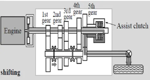
On remarque également à la Figure 2.1 que l’architecture AMT avec embrayage de transfert (PGT) n’est pas présentée. L’efficacité de la PGT dépend entre autres du type d’embrayage de transfert employé et la technologie d’actionnement des mécanismes d’engagement. En 2004, la compagnie Hitachi a publié un concept de transmission PGT à 5 rapports dont l’embrayage de transfert mouillé est couplé sur le 5e rapport (voir Figure 2.3) [37]. Ils ont également breveté la méthode de contrôle de cette architecture (US20030176257). Étant donné que l’embrayage de transfert est normalement ouvert et qu’il n’est utilisé seulement lors des changements de rapport, il y a des pertes d’énergie dues au couple visqueux parasite dans l’embrayage qui rendent cette architecture difficilement implémentable dans un véhicule électrique.
9
Figure 2.3 Architecture PGT à 5 rapports
La problématique actuelle dans le domaine des transmissions est que l’architecture qui répond le mieux aux requis du marché des véhicules électriques (coût, masse, performance, efficacité, fiabilité) est l’AMT qui possède un désavantage majeur (interruption de couple en changements de vitesse) qui ne permet pas son utilisation dans ce segment de marché émergent où le confort de conduite gagne drastiquement en importance.
2.2 Transmissions pour véhicules hybrides
Pour les applications à motorisation hybride, on retrouve une panoplie d’architectures (série, parallèle, série-parallèle, « power-split device »). Prenons d’abord le cas de l’architecture série, où seul le moteur/générateur électrique propulse les roues de la voiture. Un moteur thermique est connecté à un générateur qui convertie l’énergie mécanique en électricité.
Un accumulateur (batteries ou super condensateurs) est installé à bord du véhicule à titre de tampon pour le mode de conduite « start-stop » et pour récupérer de l’énergie au freinage. La taille (capacité électrique) de la batterie dépend du degré d’hybridation de la voiture. Les avantages de cette configuration sont les suivants :
- Moteur thermique utilisé à son régime d’opération optimal;
- Flexibilité sur le positionnement du groupe moteur thermique/générateur dans la voiture;
CHAPITRE 2 ÉTAT DE L’ART 10
Toutefois, l’architecture série possède le désavantage majeur que le moteur électrique doit être dimensionné pour fournir les appels de puissance maximale et le moteur thermique/générateur doivent être dimensionnés pour le cas où le véhicule parcourt de longues distances et qu’il roule à haute vitesse. Cela résulte en un surdimensionnement des trois composantes du groupe motopropulseur.
Afin de palier au désavantage de l’architecture série, l’architecture parallèle a été développée. Dans celle-ci, on retrouve un moteur thermique et seulement un moteur/générateur électrique qui sont reliées aux roues de la voiture. Le moteur/générateur peut ainsi être de puissance plus faible comparativement à la configuration série car le moteur thermique fournit une partie de la puissance mécanique lors des grandes demandes de puissance. Le moteur thermique doit toutefois être dimensionné afin de fournir la puissance nécessaire lorsque le véhicule parcoure de longues distances à haute vitesse. De plus, les deux machines sont généralement contraintes à fonctionner à des ratios de démultiplication discrets qui dépendent de la localisation des composantes et du type de transmission utilisé.
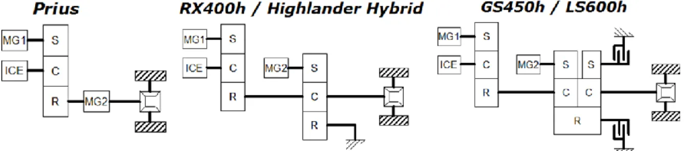
En 1971, la compagnie américaine TRW Systems Groups a développé une architecture de transmission qui bénéficie à la fois des avantages des configurations série et parallèle, soit la transmission série-parallèle dite « power-split » [30]. Cette architecture sera reprise par Toyota pour ensuite être intégrée dans la 1e génération de la Prius en 1997. Les trois générations de la transmission hybride de Toyota (HSD) sont présentées à la Figure 2.4.
Figure 2.4 Générations de la transmission «Hybrid Synergy Drive» développée par Toyota
11
Le système HSD est en fait une transmission électriquement variable qui permet de continuellement varier le ratio de démultiplication entre le moteur thermique (ICE) et les roues du véhicule. Cela permet d’exploiter le moteur thermique dans une plage d’efficacité maximale dans la majorité des points de fonctionnement du véhicule. La variation du ratio est réalisée grâce à un train planétaire et le moteur/générateur MG1. Un second moteur/générateur (MG2) est connecté à la sortie du planétaire et est relié aux roues du véhicule, par l’intermédiaire d’un train de réduction (non-représenté à la Figure 2.4). Les modes de fonctionnement de ce système sont directement liés à la valeur de la variable σ, appelée le facteur de séparation. Le facteur de séparation dépend des ratios de démultiplication du système, de la vitesse du véhicule et de la vitesse de rotation du moteur thermique.
Lorsque σ vaut 1, la totalité de la puissance mécanique du moteur thermique sert à propulser le véhicule. MG1 et MG2 ne sont pas utilisés. Lorsque σ tend vers 0, le système ressemble beaucoup à une architecture série, car la quasi-totalité de la puissance fournie par le moteur thermique est reconvertie en électricité par MG1. MG2 est alors en mode moteur et il fournit la puissance mécanique pour propulser le véhicule. Le facteur de séparation σ > 1 surtout dans le cas où le véhicule roule à haute vitesse (par exemple sur l’autoroute), afin de réduire la vitesse de rotation du moteur thermique et ainsi améliorer son efficacité de conversion. Cependant, il est important de mentionner que lorsque σ est différent de 1, il y a des pertes d’énergie dans le groupe motopropulseur dû aux boucles internes de puissance dans le train planétaire et la conversion d’énergie dans le générateur et l’électronique de puissance. Cette pénalité d’efficacité est obligatoire afin de faire varier le ratio de démultiplication de la transmission et donc elle se traduit par une augmentation de la consommation de carburant.
CHAPITRE 2 ÉTAT DE L’ART 12
13
CHAPITRE 3 ARTICLE
Avant-propos
Auteurs et affiliation
M-O. Lacerte : étudiant à la maîtrise, Université de Sherbrooke, Faculté de génie, Département de génie mécanique.
G. Pouliot : étudiant à la maîtrise, Université de Sherbrooke, Faculté de génie, Département de génie mécanique.
J-S. Plante : professeur, Université de Sherbrooke, Faculté de génie, Département de génie mécanique.
P. Micheau : professeur, Université de Sherbrooke, Faculté de génie, Département de génie mécanique.
Date de soumission :
12 décembre 2014Numéro de manuscrit :
15JAP-0009Revue :
SAE International Journal of Alternative PowertrainsTitre français :
Conception et validation expérimentale d’une transmission manuelle automatisée sans interruption de couple, employant un embrayage de transfert à courants de Foucault, pour les véhicules électriques et hybridesContribution au document :
Cet article est un résumé des principales activités liées à la conception et la validation expérimentale de l’architecture de transmission proposée ainsi que l’embrayage à courants de Foucault.Résumé français :
Les transmissions à ratio fixe présentes dans les véhicules électriques possèdent une souplesse de conduite inégalée mais l’utilisation de transmissions à multiples rapports offrent de nombreux avantages quant à l’accélération et la vitesse maximale du véhicule, le coût de fabrication, la masse et l’efficacité du groupe motopropulseur. Les transmissions manuelles automatisées équipées d’un embrayage de transfert possèdent la caractéristique de non-interruption de couple lors des changements de rapports. Toutefois, les embrayages à friction conventionnels ne sont pas les meilleurs candidats pour ce type d’application étant donné leur contrôlabilité limitée et la grande quantité d’énergie thermique à dissiper lors du ralentissement de la vitesse angulaire du moteur électrique. Cet article étudieCHAPITRE 3 ARTICLE 14
la faisabilité d’une transmission manuelle automatisée sans interruption de couple, pour le domaine des véhicules électriques et hybrides, employant un embrayage de transfert à courants de Foucault qui est hautement contrôlable, robuste, peu coûteux et sans usure. Une étude système est réalisée afin d’évaluer les avantages de l’utilisation d’une transmission multi-rapports chez les véhicules électriques, en terme d’efficacité, de coût et de masse du groupe motopropulseur. Un prototype d’embrayage a été fabriqué et intégré à une transmission manuelle automatisée à deux rapports conçue pour un véhicule électrique de 80kW. Des études numériques ont démontré qu’une transmission à deux rapports améliore l’efficacité du groupe motopropulseur de 7.2% pour un véhicule compact tel que la Nissan Leaf. De plus, l’utilisation de deux rapports permet de sous-dimensionner le moteur électrique, ce qui a pour effet de réduire le coût et la masse du groupe motopropulseur par 23.1% et 15.6%. L’embrayage à courants de Foucault a été caractérisé expérimentalement et ses performances en couple maximal corroborent les modèles analytiques par moins de 6%. Le prototype de transmission a réalisé un changement de vitesse sans interruption de couple sur banc d’essai, ce qui démontre la viabilité d’utiliser un embrayage à courants de Foucault à l’intérieur d’une transmission manuelle automatisée pour les véhicules électriques.
15
Design and Experimental Demonstration of a Seamless Automated
Manual Transmission using an Eddy Current Torque Bypass
Clutch for Electric and Hybrid Vehicles
3.1 Abstract
Electric Vehicles (EVs) with single-ratio gearbox provide high levels of smoothness, but using multi-speed gearbox can provide significant benefits in terms of vehicle acceleration, top speed, powertrain cost, mass, and energy consumption. In particular, Automated Manual Transmissions (AMTs) have characteristics of smooth shifts without torque interruption when coupled to a torque bypass clutch. However, conventional friction clutches are not best suited as torque bypass clutches because of their limited controllability and because large amount of heat must be dissipated to slow down the motor during gearshifts. This paper studies the feasibility of a seamless AMT architecture for EVs and Hybrid Electric Vehicles (HEVs) using an eddy current torque bypass clutch that is highly controllable, robust, low cost, and has no wearable parts. A system-level study using a backward-facing model is used to assess the advantages of multi-speed gearboxes for EVs in terms of energy consumption, powertrain cost, and mass. A full-scale clutch prototype is designed for a custom two-speed AMT of an 80 kW all-electric car. Numerical simulations show that a two-speed gearbox can improve energy consumption by 7.2 % for a compact class EV such as the Nissan Leaf. Moreover, using two gear ratios allows a downsizing of the electric motor, which could reduce powertrain cost and mass by 23.1 % and 15.6 %, respectively. The clutch is characterized experimentally and its maximum torque agrees well with analytical results (within 6 %). The prototype performed a seamless shift on a test bench demonstrating the viability of using an eddy current clutch for torque bypass clutches in AMT transmissions.
3.2 Introduction
3.2.1 Motivation
Wide diffusion of Battery Electric Vehicles (BEVs) is currently limited by their lack of range and high purchase costs. The battery pack is the most expensive component for a BEV with a cost around 500 $/kWh for dominant Li-ion chemistries [4]. At the module level, Li-ion batteries specific energies used in most EVs range from 80-120 Wh/kg [20], depending on cell
CHAPITRE 3 ARTICLE 16
chemistry and packaging layout. In comparison, gasoline has a specific energy of 12,000 Wh/kg [7, 9]. Even if the tank-to-wheel optimum efficiency of a BEV is about 80-85 % compared to 10-30 % for spark ignition engine vehicles [9, 11, 34], the vehicle range for the same mass of board energy will be significantly lower for BEVs. The increase of the on-board energy doesn't increase the vehicle range proportionally, because of higher vehicle consumption caused by rolling resistance and inertial forces. Powertrain efficiency must therefore be maximized in order to reduce battery size and purchase cost of BEVs and HEVs.
3.2.2 Background and literature
Most conventional EV traction systems employ a Permanent Magnet Synchronous Motor (PMSM), coupled with a single-speed gearbox in a central drive configuration. Despite high starting torque and wide constant power operation region of PMSMs, the use of a single-speed gearbox requires a motor with high torque to achieve acceptable levels of acceleration and gradeability. As the EV market grows, consumers will have greater expectations in terms of launch performances and vehicle maximum speed. First generation EVs use single-speed gearboxes as it represents less development effort and there is no traction force interruption. This trade-off leads to the need for larger and thus more expensive motors, due to high costs of rare-earth magnets, electrical steel for stator and rotor laminations and copper windings. Moreover, the direct mechanical connection between the motor and the wheels prevent the motor from operating in its optimum efficiency region. The use of a single-speed gearbox thus results in a sub-optimal use of the battery energy [24].
Series HEVs represent the simplest architecture among hybrid powertrain architectures, although they require two electric motors and an internal combustion engine of large size for long-distance sustained, high-speed driving. This arrangement is not the most efficient in charge-sustaining mode because all the driving power suffers conversion losses through the electrical path. The use of a two-speed transmission in series HEVs has proven to reduce the size of the traction motor whilst maximizing its efficiency, especially at higher driving speeds [12-13, 17]. In contrast, parallel HEVs require only one electric motor and offer a highly-efficient mechanical path to transmit power from both sources to driven wheels. However, engine speed is constrained by a finite number of gear ratios that can potentially lead to an
17
inefficient engine operation (e.g. urban driving). The Electronic-Continuously Variable Transmission (e-CVT), like the Hybrid Synergy Drive from Toyota, presents advantages of both parallel and series arrangements. However, this power-split system is designed with a mindset of blended strategy, for the purpose of a more efficient use of the liquid fuel [13]. The limited on-board electric storage and the lack of performance in all-electric mode therefore require engine operation (fuel consumption) under everyday load conditions [28]. Power-split architectures are complex and expensive, as they require two electric machines and at least one epicyclic gear train to continuously vary the engine speed ratio. Another major drawback of power-split HEVs is the limitation of the total tractive force, by the weakest side of the split. Hence, the power-split powertrain layout is not optimal to simultaneously deliver maximal on-board mechanical power and provide good vehicle performances.
Theoretical simulations and field tests show improvements in the energy consumption ranging from 4 to 15 % for EVs equipped with a two-speed gearbox, as compared to single-speed gearbox EVs [6, 10, 16-17, 24, 26-27, 31, 36, 38]. Variations in results depend mostly on the vehicle, motor and inverter specifications, drive cycle, regenerative braking constraints, and shift schedule. Fundamentally, the relevance of multi-speed transmissions for EVs is based on the criteria of low cost, high degree of reliability and mechanical efficiency, as well as compliance with consumer’s needs. The observed general trend toward driving comfort and shift quality leads the industry to upgrade from interrupted traction force transmissions to seamless transmissions [25, 32]. For efficiency, cost and complexity reasons, Automatic Transmissions (ATs) and Continuously Variable Transmissions (CVTs) are not ideal as multi-speed transmissions for EVs [22, 25]. Current ATs and belt type CVTs achieve maximum efficiencies of 86 % and 85 %, respectively, Manual Transmissions (MTs) have shown efficiencies of 96 % [14].
AMTs are a potential candidate for EVs as they are easy to manufacture, robust and low cost. The slight reduction in mechanical efficiency compared to a single-speed transmission (~97 %), due to additional churning and squeezing losses attributable to splash lubrication, is usually marginal compared to the benefit in the overall powertrain efficiency [27]. However, in a passenger car application using a two-speed transmission, a 120 kW electric motor that
CHAPITRE 3 ARTICLE 18
upshifts at 10,000 Revolutions per Minute (RPM) requires about half a second to synchronize its speed for the next gear engagement [23]. Recharging power limitations of the battery pack can easily double the duration of the torque interruption, which is not acceptable for EVs from a comfort perspective. Powershift transmissions capable of changing gears without torque interruption have been proposed and are shown schematically in Figure 3.1.
Figure 3.1 Schematic representation of powershift transmissions [29]
Dual wet Clutch Transmissions (DCTs) use hydraulic actuators and multi-plate wet clutches for better torque controllability and thermal dissipation, at the expense of efficiency due to drag and pump losses. More efficient DCTs use dry clutches and electromechanical actuators, but the high production cost and complexity still remains a challenge for their use in EVs [22, 29]. Issues regarding the primary side high moment of inertia, lining wear and thermal capacity of dry clutches can also be problematic for EVs, because of higher motor rotational speeds [1, 29]. Powershift Synchronizer Transmissions (PSTs) are defined as an AMT with oversized cone synchronizers, which lead to bulky and expensive components. The torque fill-in durfill-ing gear shifts still remafill-ins partial, due to torque and thermal limitations of the synchronizers [29]. Cone wear, degradation in shift quality over time and challenge in torque control [18] make PSTs unsuitable as multi-speed transmissions for EVs. Parallel Gear Transmissions (PGTs) solve the ride comfort problem of AMTs by adding a friction clutch, enabling parallel torque transfer through the highest gear [8, 29]. During gearshifts, the clutch controls the amount of torque to the wheels and thereby helps to slow down the motor before
19
the next gear engagement. Hitachi Group achieved torque fill-in by replacing the fifth gear of a traditional AMT by a multi-plate wet clutch [37]. Drag losses in the normally-open wet clutch are a big concern that must be addressed for EVs. Another issue for PGTs having a big ratio spread is the limited torque fill-in capability, especially during shifts from 1st to 2nd gear [29]. In conclusion, there are no multi-speed transmissions on the market that fully meet the requirements of EVs.
3.2.3 Approach, Results and Conclusion
This paper studies the feasibility of an AMT transmission architecture capable of torque fill-in that meets the high efficiency, robustness, low cost, and shift quality requirements of BEVs and HEVs. The proposed “Eddy-CT” transmission uses an eddy current torque bypass clutch that is highly controllable, uses readily available electric power, has no wearable parts, is reliable, and cost effective.
Analytical simulations of the impact of number of gear ratios on energy savings show that only two gears ratios can bring energy savings up by 7.2 % for passenger EV such as the Nissan Leaf. The “Eddy-CT” transmission functioning is then explained for both BEV and HEV configurations. The detailed design of a transmission prototype for an all-electric 2001 Volkswagen Golf is presented. Finally, experimental results on a reduced power test bench suggest the “Eddy-CT” transmission could be a viable concept for multi-speed powershift transmissions for EVs and HEVs.
3.3 Impact of a multi-speed transmission for EVs
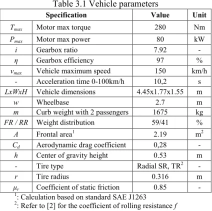
3.3.1 Vehicle parameters
The vehicle used for energetic calculations is the Nissan Leaf (see Table 3.1), which is an all-electric compact vehicle equipped with a single-speed gearbox. Motor and inverter efficiency maps are based on the traction system MΦTIVE A1 from TM4 Systèmes Électrodynamiques.
1
CHAPITRE 3 ARTICLE 20
Table 3.1 Vehicle parameters
Specification Value Unit
Tmax Motor max torque 280 Nm
Pmax Motor max power 80 kW
i Gearbox ratio 7.92 -
η Gearbox efficiency 97 %
vmax Vehicle maximum speed 150 km/h
- Acceleration time 0-100km/h 10,2 s LxWxH Vehicle dimensions 4.45x1.77x1.55 m
w Wheelbase 2.7 m
m Curb weight with 2 passengers 1675 kg FR / RR Weight distribution 59/41 %
A Frontal area1 2.19 m2
Cd Aerodynamic drag coefficient 0,28 -
h Center of gravity height 0.53 m
- Tire type Radial SR, TR2 -
r Tire radius 0.316 m
μr Coefficient of static friction 0.85 - 1: Calculation based on standard SAE J1263
2: Refer to [2] for the coefficient of rolling resistance f
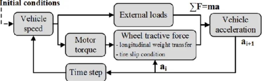
A backward-facing model is used, as it is best-suited to assess energy consumption of different powertrains on standard drive cycles. At each time step, the model calculates the road loads, including aerodynamic drag, acceleration and rolling resistances. The model also accounts for kinetic energy recuperation during braking, with a limit of 50 % of available power sent to the batteries, to account for limitations defined by non-modeled components (e.g. battery pack C-rate and energy efficiency in recharge). The motor and inverter cooling is considered to be sufficient to provide the tractive power required by drive cycles. Gear ratios and motor maximum torque are chosen to keep at least the same power envelope as the original single-speed configuration. This strategy ensures that the acceleration time, gradeability criteria and top speed are respected. Combinations of gear ratios causing a power drop after a gearshift have also been eliminated, for shift quality reasons. The acceleration time calculated by the model shown in Figure 3.2 is 10.5 s, which represents a 3 % difference with the manufacturer data and is thus considered realistic.
21
Figure 3.2 Model for gear ratio and motor torque calculations
Standard drive cycles defined by the EPA are chosen to include urban (FTP75) and highway zones (SC03), as well as different levels of driving aggressiveness (US06). A cruising speed at 100 km/h is also considered in the energy consumption calculations.
3.3.2 Components Weight
The size and the mass m of an electric motor are directly related to its maximum torque T, as shown by the following relationship [33].
(
)
(3.1)This relation has been confirmed by a benchmark of several PMSMs of different sizes, from several motor manufacturers. The benchmark confirms a relationship between the mass and maximum torque produced by a PMSM, and a proportionality factor of ~7 Nm/kg represents the market trend. The Nissan Leaf motor mass (single-speed configuration) has been estimated to 40 kg with this trend. Results between equation (3.1) and the proportionality factor have a difference of roughly 20%, which is acceptable for this comparative study. For the assessment of transmission masses, the following equation is used [19].
(( ) ) (3.2)
Where iG_max is the highest first stage gear ratio, Tmotor is the motor maximum torque and z is
the number of gears. Equation (3.2) is a trend of mass mg for coaxial two-stage passenger and
commercial vehicle gearboxes (typically five-speeds). For small number of gear ratios, it is more accurate to correlate equation (3.2) with a one-speed gearbox. Using the BorgWarner eGearDrive (28 kg), a correlation factor Rcorr of 1.5 has been found.
CHAPITRE 3 ARTICLE 22
3.3.3 Components Cost
First, a calculation of raw material cost has been done using estimated motor masses [5]. To account for manufacturing, assembly, engineering development, and overhead costs, a cost model has been found [3] to evaluate the cost of an electric traction system (21 $/kW + 425$). Comparison of these results leads to the conclusion that raw material represents about 30% of the production cost of a PMSM. The cost model was not directly used for the motor cost assessment because the motor torque is not defined as an input parameter. To assess the transmission production costs, the following trend is used [19].
(3.3)
The relative selling price (RSP) is based on manually shifted passenger car transmissions. A RSP of 1 corresponds to a 6-speed transmission with an input torque Tmotor = 350 Nm and a
maximum transmission ratio (1st gear) of iG,max = 5.5. The production cost of this transmission
has been estimated at 600 $. Extra costs, based on [15], have been added for two and three speed transmissions, to account for additional components (actuators and gearshift mechanisms).
3.3.4 Results
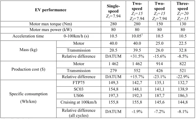
The analysis of different gear ratios Z for two-speed configurations shows that the highest gear ratio has a great influence on vehicle specific consumption (Figure 3.3).
23
Figure 3.3 Specific energy consumption as a function of the highest gear ratio, for two-speed configurations
This trend is mainly due to the fact that the use of a high gear ratio allows a reduction in the motor maximum torque. Operating points calculated from drive cycles thus moves towards more efficient zones on the motor efficiency map. The following table summarizes the results of the simulation for the most promising powertrain options for EVs in terms of efficiency, overall cost and mass.
Table 3.2 EV performance for different powertrain options
EV performance Single-speed
Z1=7.94 Two-speed Z1=15 Z2=7.94 Two-speed Z1=15 Z2=7.94 Three-speed Z1=20 Z2=15 Z3=7.94
Motor max torque (Nm) 280 280 150 130
Motor max power (kW) 80 80 80 80
Acceleration time 0-100km/h (s) 10.5 10.051 10.5 10.5 Mass (kg)
Motor 40.0 40.0 25.0 22.5
Transmission 20.5 39.5 26.0 32.8
Relative difference DATUM +31.5% -15.6% -8.5% Production cost ($)
Motor 1 462 1 462 914 822
Transmission 279 552 426 521
Relative difference DATUM +15.7% -23.1% -22.9%
Specific consumption (Wh/km) FTP75 149,3 142,7 135,1 132,7 SC03 154,8 148,1 141,1 138,9 US06 197,3 192,3 187,7 186,3 Cruising at 100km/h 155,8 155,8 145,6 144,8 Relative difference
(all cycles) DATUM -1.9% -7.2% -8.1% 1: Tire slip limitation
CHAPITRE 3 ARTICLE 24
These results show that:
Simply adding a second gear ratio to the original powertrain does not reduce its production costs and provides slight energy savings. The full-benefits of using a two-speed gearbox are realized when the traction motor is downsized such that the EV has the same acceleration time as in the single-speed case. Only then the powertrain cost and mass decrease, and the energy consumption is significantly improved.
For the single-speed configuration, the acceleration time (0-100 km/h) requirement imposes a motor producing a high starting torque (280Nm). In a real-world use, the average motor torque requirement is only 32-35 Nm on FTP75 and SC03, and 44 Nm for US06 drive cycles. Most of the motor operating points are therefore outside of the 90 % and above efficiency zone.
For a given cooling system, the two-speed gearbox makes the motor operate at higher efficiencies, which implies lower copper winding temperature, hence a greater reliability. Longer peak power transients are possible before reaching the maximum allowable temperature of the copper wire insulation.
The use of a multi-speed gearbox lowers EV costs as they enable a substantial downsizing of the costly electric motor and battery. For example, the Nissan Leaf 24 kWh battery pack costs approximately 500 $/kWh. The use of a three-speed gearbox increases the powertrain efficiency by 8.1 %, which allows a battery downsizing of 1.94 kWh for the same driving range. Therefore, a 972 $ saving can be made of the EV production costs.
3.4 Eddy Current Torque Bypass Clutch AMT for EVs
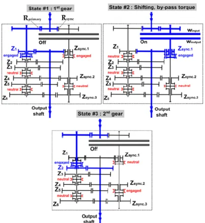
The proposed transmission architecture for EVs is a seamless AMT using an eddy current torque bypass clutch, as shown in Figure 3.4. The “Eddy-CT” transmission is largely based on conventional MT components, because of their high levels of robustness, efficiency and low cost. The number of gears, their ratios and the differential location can be adapted to fit many applications (RWD, FWD, motorized axle, etc.). The power path through a six-speed transmission example is presented for a gear upshift from 1st to 2nd gear.
25
Figure 3.4 Eddy current torque bypass clutch AMT, power paths for an upshift from 1st to 2nd gear
The proposed transmission addresses the main issues of shift quality and management of high levels of motor kinetic energy during gearshifts by using a non-contact clutch which doesn’t wear out over time and has no drag losses. The eddy current clutch uses a fixed electromagnet to avoid the use of carbon brushes and slip rings and enhance clutch reliability. The high controllability of excitation current in the clutch electromagnet provides an excellent torque fill-in capability required for seamless gearshifts. Gearset Z1 to Z6 is very similar to an AMT,
except that an additional Rprimary gear allows physical clearance for the clutch and limits the
rotational speed of Z1 gear in overrunning mode. After disengagement of Z1 gear, the clutch is
activated to transfer torque to the transmission output via the preselected Zsync.1 gear, as long as
the electric motor has not reached the target speed for the next gear engagement. The usual cone synchronizers for engagement of Z1 to Z6 gears can be replaced by cheaper and more
robust dog-rings because speed matching can be achieved by the electric motor. Each gear ratio Z has its associated ratio Zsync in order for the eddy current clutch to operate in its
optimum slip speed and maximize its torque production. Gear ratios Zsync are chosen to fulfill
CHAPITRE 3 ARTICLE 26
The clutch slip speed (winput – woutput) must be greater than 0 RPM in order to transmit a
positive torque;
The clutch output speed should be as high as possible for every gearshifts to minimize the required coupling torque.
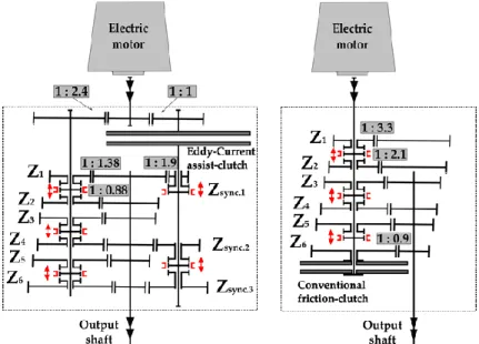
Linking the clutch output to more than one ratio gives a big advantage over conventional PGTs because this lowers the coupling torque requirements, which results in a much cheaper clutch. As an example, the comparison between the proposed “Eddy-CT” transmission and a conventional PGT, where the friction clutch is replacing the 6th gear synchronizer, is shown in Figure 3.5.
Figure 3.5 Transmission layouts: eddy current torque bypass clutch AMT (left) and conventional PGT (right)
The assumptions are:
The gear upshift from 1st to 2nd gear occurs when the traction motor revolves at 10,000
RPM;
The 100kW electric motor is at constant power before and after the gearshift;
The torque bypass clutch completely fills the torque interruption during the gearshift; Gear ratios are common values of conventional passenger car gearboxes, and 1st and
2nd ratios are similar for both transmissions;
27
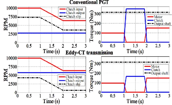
Rotational speeds and clutch torque during the upshift event are shown in Figure 3.6.
Figure 3.6 Upshift from 1st to 2nd gear for a conventional PGT (top) and the “Eddy-CT” transmission (bottom)
For a same transmitted power of 100 kW, the torque requirement for the PGT clutch is 350 Nm compared to 166 Nm for the eddy current torque bypass clutch. The “Eddy-CT” transmission can connect the torque bypass clutch to the appropriate ratio in order to maximize the clutch output speed, which has the effect of reducing the clutch coupling torque requirement. A conventional PGT doesn’t have this mechanical advantage since the clutch is constrained to be connected to the highest gear ratio of the transmission to ensure torque fill-in for all gear ratios.
3.5 Eddy Current Torque Bypass Clutch AMT for HEVs
Adding an electric motor on the clutch output shaft enables the eddy current torque bypass clutch AMT to be a series-parallel hybrid, as shown in Figure 3.7. This hybrid architecture has an advantage over the single-motor EV layout regarding torque fill-in capability. The electric motor can be used during downshifts to improve shift quality, either by reducing the internal combustion engine synchronization time via the clutch or by directly transferring mechanical power to the wheels via Zsync gears.
CHAPITRE 3 ARTICLE 28
Figure 3.7 Eddy current torque bypass clutch AMT for HEVs
In all-electric mode, the multiple Zsync gears reduce energy consumption as well as the electric
traction motor maximum torque requirement. The eddy current torque bypass clutch allows the proposed transmission to have the same smooth and seamless torque transmission properties as power-split devices, in charge-sustaining and blended mode. The series mode is available when the vehicle is stationary, by only engaging Zsync.1 gear for battery charging.
Operational modes of the proposed series-parallel architecture are: Regenerative braking;
Engine start-up by the electric motor (via the eddy current clutch or Zsync.1 gear);
Eddy current braking through the eddy current clutch; All-electric mode (charge-depleting mode);
Motor assist (blended mode);
Power split mode (charge-sustaining mode); Standstill charge mode (series mode);
3.6 Eddy Current Torque Bypass Clutch Design
3.6.1 Representative Design Requirements
The eddy current torque bypass clutch is designed for the all-electric Volkswagen Golf 2001 prototype. It is currently equipped with a two-speed AMT without torque fill-in capability
29
during gearshifts. The electric traction system is a TM4 Systèmes Électrodynamiques MΦTIVE A. A third gear is added to the actual two-speed AMT to provide a torque fill-in capability with the eddy current clutch during gearshift from 1st to 2nd gear. Table 3.3 summarizes the transmission specifications and the torque bypass clutch requirements.
Table 3.3 Transmission specifications and torque bypass clutch requirements
Transmission characteristics Value Unit
Tmax Motor max torque 170 Nm
Pmax Motor max power 80 kW
n Motor operational speed 0-10,000 RPM
Iinput Input shaft inertia (with the motor) 0.15 kg-m2
Z1 1st gear ratio 33:10 -
Z2 2nd gear ratio 35:18 -
Z3 3th gear ratio (for clutch) 34:26 -
Tclutch_max Required clutch coupling torque 193 Nm
Δω Clutch slip range (gearshift at max speed) 6037 to 1929 RPM noutput Clutch output max speed 6725 RPM
rext Clutch max external radius 0.132 m
dclutch Clutch max axial length 0.090 m
Emax Clutch max heat release for each gearshift1 27,000 J 1: Upshift at 10,000 RPM and 80 kW, no regenerative braking by the motor
3.6.2 Working Principle and Analytical Model
An eddy current clutch relies on the principle of electromagnetic coupling between two parts moving at different speeds. When a conductive part is moving perpendicular through a time-varying or an inhomogeneous magnetic field, an electric field is induced, which in turn generates eddy currents within the conductive material according to Faraday’s law of induction. These circulating eddies are swirling in such a way to create a secondary magnetic field which oppose the change in primary magnetic flux (Lenz’s law). The interaction between these fields causes an electromagnetic coupling force (Lorentz force). The magnitude of these forces depends primarily on the varying field amplitude, relative speeds (slip speed) and geometric dimensions of rotating components. The main components of the proposed eddy current torque bypass clutch are shown in Figure 3.8.
CHAPITRE 3 ARTICLE 30
Figure 3.8 Exploded view of main components of the proposed eddy current clutch
A magnetic field is generated by an electromagnet and the resulting magnetic flux is conducted to a toothed rotor using a ferromagnetic stator, both fixed. The doubly toothed rotor (pole assembly), also made of ferromagnetic material, channels the magnetic flux using seven teeth to create a time-varying magnetic flux across the drag cup rotor (drum). The drum is made of aluminum because this material has a suitable electrical resistivity with respect to the clutch slip range and physical dimensions. Furthermore, this low-inertia drum is connected to the high speed side of the clutch (motor side) to minimize the supplemental moment of inertia. The pole assembly is connected to the output shaft by means of the 3rd gear. A relative speed between the pole assembly and the drum is always present to allow a torque production regardless of the operating conditions of the transmission. When the electromagnet is off, the remanent magnetic induction inside the stator is so small that the off-state torque (<< 1Nm) can be neglected. Clutch torque versus slip speed is calculated with Wouterse’s analytical model [35]. This simple 1D-model is useful for performing parametric calculations of clutch torque versus slip speed. The equation for the maximum electromagnetic force ̂ exerted by a pair of teeth of the pole on the drum is given by equation (3.4). The slip speed at which this maximum force is generated is called the critical speed vk, and is given by equation (3.5).
31
̂ √( ) √( ) (3.4)
√( )
√( ) (3.5)
Table 3.4 Definition of symbols used in (3.4) and (3.5)
Symbol Definition Unit
µ0 Magnetic permeability of vacuum H/m
c Ratio of total contour resistance to resistance of contour part under the pole - Ratio of zone width, in asymptotic current distribution around poles, to air gap -
D Ferromagnetic pole diameter m2
Air gap induction at v = 0 (no slip speed) T
Specific resistance of disc material Ω-m
v Slip peripheral speed m/s
A typical torque versus slip speed profile for the eddy current device is shown in Figure 3.9. At low-speed, the reaction magnetic field of the eddy currents is negligible compared to the original induction B0, which means that the electromagnetic force is proportional to the slip
speed. Beyond the critical speed, the dissipated power in the drum reaches a maximum value, because of the reduction of magnetic induction under the pole. The drum electrical resistivity has a strong effect on the critical speed and no effect on the maximum force ̂ for a given air gap induction. Thus, drum heating during a gearshift moves the clutch torque versus slip speed profile towards higher rotational slip speeds. This effect must be accounted for selecting the drum rotor material.
CHAPITRE 3 ARTICLE 32
The coupling torque profile as a function of the slip speed may be written as:
̂
⁄ ⁄ (3.6)
(3.7)
Geometric parameters of the clutch are presented in Figure 3.10 and Table 3.5 for convenience.
Figure 3.10 Clutch parameters, cross-sectional view (left) and frontal view (right)
Table 3.5 Geometric parameters of the proposed eddy current clutch
Eddy current clutch characteristics Value Unit
rext External clutch radius 132.2 mm
dclutch Clutch axial length 91.0 mm
rdrum Drum mean radius 98.5 mm
ddrum Drum axial length 42.5 mm
dpole Poles axial length 33.0 mm
tdrum Drum thickness 3.0 mm
x Distance between teeth pair faces 4.3 mm hext External teeth height 9.6 mm
hint Internal teeth height 23.3 mm
text External rim thickness 5.0 mm
tint Internal rim thickness 6.7 mm
lpol / (lpol + lint-pol) Polar length 0.5 -
33
3.6.3 Clutch Magnetic Design
The first design step is to compute the clutch critical torque and critical slip speed from the powertrain specifications. Because the clutch torque varies with slip speed (see Figure 3.9), the maximum clutch coupling torque must be higher than the required coupling torque (193 Nm, see Table 3.3) to perform seamless gearshifts. Second, the drum rotor is given a radius and a thickness (rdrum and tdrum) using Wouterse’s model. Using the critical torque and slip
speed, this step aims to find a drum radius and thickness that makes the air gap between the toothed teeth faces (parameter x, see Figure 3.10) not too small (to allow components thermal expansion and deformation), nor too large (to limit the magnetic flux fringing across the drum rotor). The third and last design step is to size the toothed rotor teeth (equivalent pole diameter D), again using Wouterse’s model, for the clutch to develop the required critical torque value at the specified slip speed. Details of the magnetic design of the proposed eddy current clutch is presented by Pouliot [21].
3.6.4 Clutch Mechanical Design
The aluminum drum thickness is chosen to have enough thermal capacity to prevent an excessive temperature rise during gearshifts. As with static strengths, the endurance limit (e.g. threshold at 5x10⁸ cycles for non-ferrous alloys) decreases with an increase in temperature. It is also well known that creep is strongly influenced by temperature and stress level. Analytical and finite element analysis show that principal stresses in the drum are tensile stresses due to centrifugal forces. Drum fatigue life assessment is achieved through road cycle and stress spectrum calculation, Rainflow Counting method and application of Miner’s linear damage rule. A 3 mm drum thickness made of 6061-T6 satisfies both magnetic and fatigue requirements.
Upper and lower airgaps between the drum and the doubly toothed rotor are set to 0.9mm and 0.4mm, respectively. Drum cooling between gearshifts using an oil jet is implemented to prevent thermal build-up, as shown in Figure 3.11. Depending on clutch duty-cycle and packaging layout, other cooling methods may be applicable, such as forced air convection.
CHAPITRE 3 ARTICLE 34
Figure 3.11 Clutch cooling, lubrication and mounting arrangement on the input shaft
3.7 Experimental Results
3.7.1 Test Bench Setup
Clutch characterization and seamless gearshifts are performed on a test bench, using the same TM4 motor as in the all-electric Volkswagen Golf. A second TM4 motor (used as a generator) is connected at the transmission output to emulate the inertial and external loads of the vehicle, as shown in Figures 3.12 and 3.13.
35
Figure 3.13 Test bench layout
A 27 kW three-phase thyristor rectifier produces the DC voltage required by both electric motors. An electronic DC load dissipates the extra electrical power generated by the load motor during gearshifts. The test bench management and data acquisition are performed using an Opal-RT system.
3.7.2 Clutch Performance
The magnetic induction B0 in the drum is measured at electromagnet excitation currents of up
to 126 Adc. Experimental induction measurements agree well with finite-element simulations for excitation currents up to 50 Adc [21], suggesting that the BH curve for the AISI 1018 is different than expected in the saturation zone. At 126 Adc, the magnetic induction is 1.07 T. The clutch torque versus slip speed is then measured for an excitation current of 16 Adc and 30 Adc, as shown in Figure 3.14.
CHAPITRE 3 ARTICLE 36
Maximum torque predictions using Wouterse’s model agree well with experimental data, with 5.3 % or less error. The results at higher slip speed are slightly different due to drum initial temperature uncertainty and the test procedure that requires clutch activation ~1 s prior to the torque measurement [21]. This delay allows the aluminum drum to heat up and increases its electrical resistivity. The initial drum temperature is estimated by measuring gearbox oil temperature. Clutch torque versus slip speed experiments cannot be performed at higher excitation currents for technical reasons. Using Wouterse’s equations and magnetic induction measurements, clutch torque versus slip speed predictions at 126 Adc are shown in Figure 3.15. An initial drum temperature of 80 °C is assumed, so the temperature reached at the end of a gearshift at maximum load (27 kJ of heat release in the drum) is 220 °C.
Figure 3.15 Eddy current clutch torque versus slip speed at 126 Adc
The eddy current clutch prototype doesn’t meet the torque requirement of 193 Nm on the slip speed range (see Table 3.3), because of clutch geometric constraints imposed by the retrofit in an existing two-speed AMT. Without clutch axial length limitations, a clutch design with a thinner (1.2 mm) and larger drum (95 mm) would produce the required 250 Nm to ensure a complete seamless gearshift at motor peak power [21]. The mass of the clutch prototype is 25.1 kg and the torque density is 7.1 Nm/kg, which is much lower compared to dry and wet friction clutches (18 Nm/kg to 64 Nm/kg)2. Possible improvements of the eddy current clutch include the use of steel with a higher magnetic saturation level for the stator and the doubly toothed rotor.
2
![Figure 2.2 Schémas d'architectures de transmission dites "Powershift" [29]](https://thumb-eu.123doks.com/thumbv2/123doknet/2870814.72167/20.918.173.728.735.1031/figure-schémas-d-architectures-transmission-dites-powershift.webp)
![Figure 3.1 Schematic representation of powershift transmissions [29]](https://thumb-eu.123doks.com/thumbv2/123doknet/2870814.72167/32.918.177.709.293.561/figure-schematic-representation-powershift-transmissions.webp)