HAL Id: hal-01877854
https://hal.archives-ouvertes.fr/hal-01877854
Submitted on 20 Sep 2018
HAL is a multi-disciplinary open access archive for the deposit and dissemination of sci-entific research documents, whether they are pub-lished or not. The documents may come from teaching and research institutions in France or
L’archive ouverte pluridisciplinaire HAL, est destinée au dépôt et à la diffusion de documents scientifiques de niveau recherche, publiés ou non, émanant des établissements d’enseignement et de recherche français ou étrangers, des laboratoires
Impact damage prediction in thin woven composite
laminates – Part II: Application to normal and oblique
impacts on sandwich structure
Florian Pascal, Ange Rogani, Bassam Mahmoud, Pablo Navarro, Steven
Marguet, Jean-François Ferrero
To cite this version:
Florian Pascal, Ange Rogani, Bassam Mahmoud, Pablo Navarro, Steven Marguet, et al.. Im-pact damage prediction in thin woven composite laminates – Part II: Application to normal and oblique impacts on sandwich structure. Composite Structures, Elsevier, 2018, 190, pp.43 - 51. �10.1016/j.compstruct.2018.02.013�. �hal-01877854�
Impact damage prediction in thin woven composite
laminates – Part II: Application to normal and oblique
impacts on sandwich structure
F. Pascala, A. Rogania, B. Mahmouda, P. Navarroa, S. Margueta, J-F. Ferreroa
aUniversit´e de Toulouse, Institut Cl´ement Ader, FRE CNRS 3687,
UPS/INSA/ISAE/Mines Albi, 3 rue Caroline Aigle, 31400 Toulouse, France
Abstract
This article concerns the Finite Element modeling of impacts on compos-ite sandwich structures. Low velocity normal impacts and medium velocity oblique impacts on sandwich panels made with woven composite skins and a polyurethane foam core are investigated. The ply orientations and materials of the woven composite laminate skin are varied. The woven skin is modeled using a semi-continuous approach, described in the first part of this two parts article, in which the behavior of the bundles of fibers and that of the resin are disconnected. The foam core is represented with solid elements with a continuous material law. This modeling strategy provides results accurate enough to represent the damage scenario observed experimentally with an acceptable calculation time. The numerical results are used to analyze the damage mechanisms leading to the final fracture shape.
Keywords: Woven fabric composite, Foam core, Damage, Impact, Explicit F.E modeling, Sandwich structure
1. Introduction
This article deals with the modeling of impacts on composite sandwich panels made with thin woven composite skins and a polyurethane foam core. Low velocity normal impacts and medium velocity oblique impacts are in-vestigated. This paper is the second part of a two-parts article. Indeed the modeling strategy presented in the first part is used here to model the skin. Due to their low mass to stiffness ratio, composite sandwich structures are involved more and more in the designing of aeronautical structures. Con-sequently, composite sandwich panels can be subjected to an impact in flight with a greater probability. The impacts can be normal to the panel or with an angle, and the failure of the skin can have catastrophic consequences. Thus, understanding and predicting impact damages in such structures is required.
Impacts on composite sandwich structures has been widely studied [1]. Indeed, due to the particular architecture that involves at least two different materials (for the skins and for the core), the impact behavior of these struc-tures is complex. In [2, 3, 4, 5] several damage scenario depending on the panel height, the skin thickness and the core density have been identified. Indeed, impact can lead to a compressive failure of the upper skin, a shearing failure of the foam core or a tensile rupture of the lower skin.
The modeling of the impact response of sandwich composite panels can be performed at different scales, depending on the desired precision. Many authors have developed analytic models based on beam theories resting on elastic foundations in order to evaluate the influence of geometrical and ma-terial parameters on the global response of sandwich panels [6, 7, 8].
Never-theless, these modeling strategies can not represent damage scenarios during impact. To do so, Finite Element Methods have to be used.
Generally, for a better representation of the damage scenario, the compos-ite skin and the core have to be modeled separately. This is all the more true when complex loading, like oblique impacts, are studied [9, 10, 11]. For the modeling of the woven composite skin, the representation scale varies from the homogenized skin to the representation of the bundles of fibers with solid elements [12, 13, 14, 15, 16, 17, 18, 19]. A detailed literature survey can be found in part I of this two-parts article.
Likewise, for the modeling of the foam core, the strategies vary with the precision needed for the representation of the damages. In the continuous approach, the idea is to associate a simple continuous mesh with a complex homogenized constitutive material law. One way to compute the particular behavior of foams is to define a yield criterion in the material law to deal with the plateau observed in the crushing [20]. It is also possible to add a term depending on the volumetric strain is added to compute the hydro-static pressure [21]. Another strategy consist in representing explicitly the microstructure of the foam core. [22] has developed a Finite Element Mod-eling at the scale of the cells of the material. In order to avoid prohibitive calculation time, only truss element are used and the modeling scale is var-ied. With this strategy, damage phenomena are well represented. Finally, many works rely on the use of an idealized microstructure which can come from experiments or from mathematical constructions based on polyhedra [23, 24, 25]. These models are well suited to understand the physics that drives the response at the macroscopic scale. However, they generally
in-duce a huge computational time directly related to the fine description of the microstructure.
In this paper, a Finite Element Modeling of sandwich panels at scale that allows a precision high enough to be able to analyze the damage scenario, without having prohibitive calculation time is proposed. The woven com-posite skin is modeled using the semi-continuous strategy described in part I. The foam core is represented with solid elements with an homogenized property. The modeling strategy is presented in the first section. In the sec-ond section, low velocity impact tests on sandwich panels are modeled and compared to experimental results. Three different skin configurations are studied. In the third part, medium velocity oblique impacts are modeled. The results are then analyzed to describe the damage scenario.
The proposed modeling strategy allows a representation good enough to reproduce the impact response observed experimentally. More, the results can be used to observe, analyze and understand better the damage chronol-ogy.
2. Sandwich structure modelling
The studied sandwich structure is composed of a skin with two or three plies of 5-harness carbon/epoxy and 8-harness glass/epoxy woven fabric, and an A51 Rohacell foam core.
2.1. Woven skin modelling
The strategy used for modeling the woven composite laminate that com-pose the skin of the sandwich structure is fully described in Part 1 of this paper. It consists in modeling each ply bundles with a truss structure which
follows the woven pattern geometry. The mesh size respects the woven fabric pattern i.e. the distance between two bundles. The interlacing of the warp and the weft tows at the crimp regions is approximated with oblique rod elements. The epoxy matrix which embed the fibre bundles is modeled with damageable shell elements placed at the neutral axis of the ply. The connec-tion between the rods and the shell elements is made at the nodes through rigid links. Finally, the woven laminate is created by connecting each ply with a specific cohesive interface element which allow a feasible connection between shell elements.
This strategy allows to both represent the continuous elastic behaviour of the undamaged ply and the discrete behaviour of the woven ply when resin is damaged and fibre bundles are in a non-stabilized state.
2.2. Foam core modelling
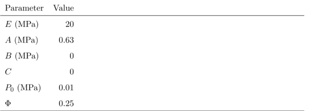
The foam is modeled with a homogeneous property and a material law known in the explicit code Radioss as FOAM PLAS. This law is adapted to the low density foam with a visco elasto plastic behavior in compression. The crushing behavior of the foam cells is represented by a stress plateau with irreversible strains. An elasto plastic behavior is introduced in the deviatoric part of the stress tensor in order to represent this phenomenon.
σdevplas= A + B(1 + Cγvol) with γvol= V V0
− 1
where σplasdev is the plastic stress applied to the principal stress of the deviatoric tensor, γvol is the volume strain and A, B and C are modeling parameters.
spher-ical stress tensor.
σijspher = −P δij with P = − P0γvol 1 + γvol− Φ
where δij is the Kronecker symbol, Φ is the foam porosity and P0 the initial air pressure.
Low velocity tests realized on cylindrical foam specimens ([Navarro, 2010] [Aubry, 2013]) have been used to identify the parameters of this model. The used parameters are given in Table 1.
3. Drop weight impact damage prediction
This section aims to show the ability of the proposed modeling to predict the damage induced by a drop weight impact onto a sandwich structure made with woven composite skins and a foam core.
3.1. Drop weight impact test
Twelve sandwich structure coupons have been impacted with a drop weight test bench. Several laminate configurations have been studied for the sandwich skin. The idea was to observe the behavior of the specimen with different ply orientations and materials. The three configurations inves-tigated are presented in table 2. Four impacts have been realized for each configuration.
The specimen dimensions are 100×100×20 mm. The sandwich structures are placed on a rigid support as illustrated on Fig. 1. The steel impactor has a 20 mm diameter hemispheric shape and a mass of 2 kg. It impacts the specimen with an initial velocity of 3 m/s. That is to say an impact energy
of 9 J. The reaction force and the impactor displacement are recorded during impact.
3.2. Modelling results
A modeling of this test, relying on the strategy presented in Section 2, is proposed (Fig. 2). The modeling of the specimen involves 120,000 user developed finite elements for the carbon material configurations and 225,000 for the glass material configuration. Indeed, the mesh size is 1.4×1.4 mm for the carbon material and 0.5×0.5 mm for the glass material in agreement with the measured woven fabric patterns. The boundary conditions are in-troduced by the use of a contact between the specimen and a rigid wall. The impactor is a rigid sphere with the adequate mass and initial velocity. All the computations are performed with the explicit finite element code RADIOSS on 60 cores from HPC resources. Time calculation is about 30 to 90 mins.
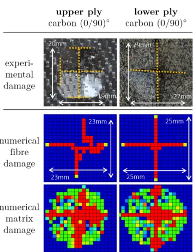
3.2.1. Analysis of a carbon laminate with two identical orientations [(0/90)2] C0C0 is a configuration with two plies of carbon/epoxy woven fabrics with the same orientation. After an impact on this configuration, a crack in the shape of a cross is visualized on the two plies with a longer crack on the lower ply. The ply damage is compared with the one obtained with the FEM in the Fig. 3. The first column shows the damage of the upper ply and the second one the damage of the lower ply which was experimentally obtained by removing the foam from the skin after the test. The first line shows the experimental crack. The second and the third lines show the fibre and the resin numerical damages. In order to simplify the visualization of the rod failure (fibre damage), a yellow/red style contour on the woven element has
been used. Yellow means that only one rod has failed in the element whereas red contour means that at least two rods have reached their failure criteria.
The cracks in the shape of a cross are well captured by the modeling in the two plies. The sinuous path of the crack is well represented by the failure of the rod at the crimp regions. The matrix is first damaged, then the rods fail in tension. The maximal relative error on the crack length is lower than 21%.
In Fig. 4, the modeling is used to explain the damage scenario during the impact test. It can be split up in four steps reported on the force versus time curves: (i) the first load decrease is due to a line crack obtained in the lower ply of the laminate, (ii) a crack is then initiated in the upper ply at the maximal load, (iii) the rupture in the shape of a cross in the two plies of the laminate is observed after a significant decrease of the load, (iv) the cracks propagation is done at a constant load. The remaining stiffness is provided by the crushing of the foam and the bending stiffness of the four petals of the cracked laminate.
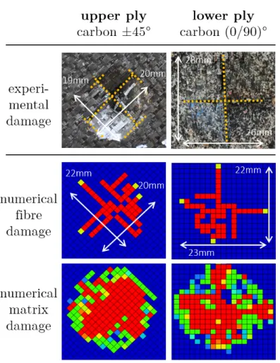
3.2.2. Analysis of a carbon laminate with mixed orientations [(0/90),±45] The second configuration is composed of two plies of carbon/epoxy woven fabric: one lower ply oriented at ±45o and the upper ply oriented at (0/90)o. The Fig. 5 shows a comparison between experimental and numerical fracture shapes after the impact. The same representation style than in the previous section is used. For a carbon laminate with mixed orientation, the crack path is driven by the orientation of the fibre in each ply. Indeed, a (0/90)o cross is observed on the lower ply and a ±45o on the upper ply. This fracture shape is well captured by the FEM with a relative error on the crack length lower
than 21%.
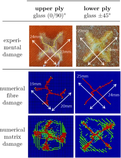
3.2.3. Analysis of a glass laminate with mixed orientations [±45,(0/90)] For the third configuration, a laminate with mixed orientations have been made with a 8-harness glass/epoxy woven fabric. The lower ply is oriented at (0/90)o and the upper ply is oriented at ±45o. The experimental and numerical fracture shapes after the impact test are represented in the Fig. 6. The experimental results are different from the observations made on the carbon laminate with mixed configurations. Indeed, the failure of the lower ply is oriented at (0/90)o, which corresponds to the fibre orientations of the ply. However, for the upper ply, the crack propagation seems to be influenced by the lower ply failure and a (0/90)o cross is also observed in this ply. This crack orientation is slightly captured by the FEM. The sinuous crack path of the upper ply tends to illustrate the influence of the lower ply on the crack propagation of the upper ply. The maximal relative error on the crack length is also lower than 21%.
4. Oblique impact damage prediction
In this section, the capacity of the modeling strategy to predict the re-sponse to an oblique impact at 90 m/s onto a sandwich structure is investi-gated.
4.1. Oblique impact test
Nine sandwich structure coupons have been impacted with a gas gun de-vice. Several laminate configurations have been studied for the sandwich skin. Three specimens are impacted for each configuration in order to check the
reproducibility of the experimental results. Three configurations, presented in Table 3 are under investigation.
The specimen are 200mm long and 240mm width. The skins are about 1 mm thick and the foam is 20 mm thick. The impactor is a spherical steel ball of diameter 19 mm and mass 28 g. The impact angle measured from the surface of the upper skin is 15o. The testing device is presented in the Fig. 7– a. The test is recorded with a high-speed digital camera (Photron FastCam APX RS) at a frame rate of 36000 fps and a resolution of 512×128 pixels. The use of a speckle on the impactor, and the use of a digital image correlation (DIC) algorithm developed at the laboratory [26], enables a fine computation of the velocities of the impactor. The signal is smooth enough to deduce the acceleration of the impactor, and thus the normal impact force FN. Some examples of the tracking of the speckled impactor by the DIC algorithm are given in the Fig. 7–b. The modeling developed for the simulation of this test reuse the same strategy as presented before for the drop weight normal impact test. There is simply one more ply for the skins. Some details on the model are shown in the Fig. 7–c. At last, the model involves around 1.2 Mdof and is run on a 60 cores parallel computer for a computational time of about 60 minutes.
4.2. Modelling results
4.2.1. Influence of the orientation of the plies from the impact axis
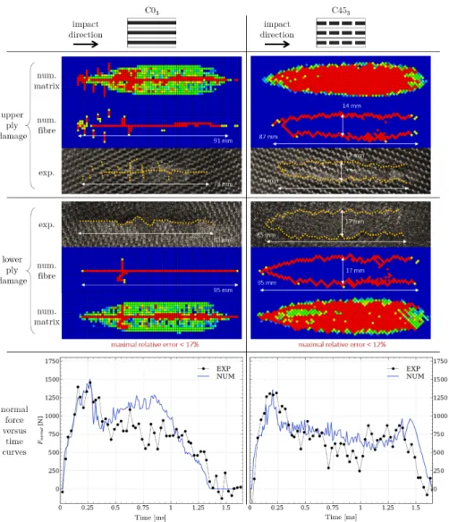
The overall results for the two configurations C03and C453 are illustrated in the Fig. 8. The damage shapes and the normal force versus time curves obtained with the FEM are compared to the experimental results. All the pictures dimensions fit the same scale. The fibre failures are highlighted with
yellow dotted lines. The impact occurs from left to right. The left column shows the C03 configuration when all the plies are oriented at 0o from the impact axis and the right column shows the C453 configuration when all the plies are oriented at 45o from the impact axis.
The experimental damages are very different for the two configurations. The C03 configuration shows only one crack following a roughly straight tra-jectory with multiple crack branches on the upper ply. Concerning the C453 configuration, two parallel straight lines with a V-shape crack initiation are observed. The crack lengths are very close between the two configurations. Besides, for the C03 and C453 configurations, the crack is about 10% greater on the lower ply than on the upper ply.
The FEM gives a crack damage very close to the experimental observa-tions. The straight cracks for the C03 configuration and the two parallel cracks for the C453 configuration are well represented. Quantitatively, the maximal relative error on the crack lengths is lower than 17%. Besides, the experimental and the numerical force vs time curves follow similar trends for both configurations. It highlights a good overall behavior of the modeling during the impact.
Consequently, a further analysis of the damage scenario has been con-ducted by using the FEM. The Fig. 9 shows the evolution of the skin damage during the impact of the C453 configuration. The formation of the V-shape fracture is thus explained in three steps: (A) the fibres of the ply fail in ten-sion, (B) the crack propagates at ±45o from the impact axis like during the drop weight impact test and (C) the imposed displacement of the ball tends to propagate the ±45o crack in the 0o direction. This phenomenon applies
equally to the three plies but at different times.
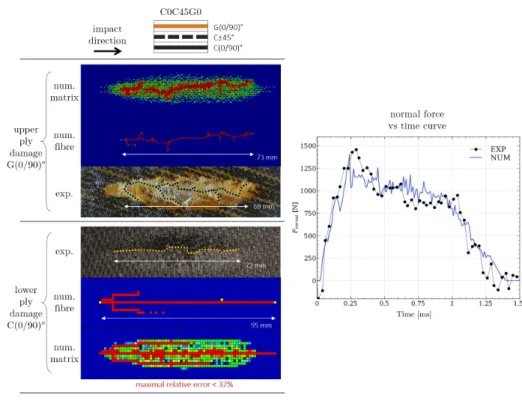
4.2.2. Analysis of a mixed materials and orientations laminate [C0C45G0] Finally, a more complex laminate is studied with the C0C45G0 config-uration. The idea is to assess the performance of the modeling strategy to predict the damage due to an impact onto a mixed material and orientation laminate. The results of both experimental and numerical studies for this configuration are compared in the Fig. 10.
As expected, a more complex crack propagation is observed compared to the mono-material and mono-orientation laminate configurations. First, there is a straight crack in the lower ply which corresponds to the (0/90)o carbon ply. This result is quite similar to the last reported on the C03 config-uration. However, for the upper ply which corresponds to the (0/90)o glass ply, the crack propagation seems to be strongly influenced by the ±45o car-bon ply at the middle of the laminate. Indeed a straight crack was expected corresponding to the fibre orientations of the ply but there is a very sinuous crack. This result is consistent with the last observation on the drop weight impact test with the G45G0 configuration (see section 3.2.3). Once again, a competition seems to appear between the ply behavior and the laminate structure influence.
Despite the complexity of the configuration represented, the results ob-tained are very correct on both fracture shapes and normal force curve. The damage of the glass ply is very well represented by the model. Indeed, the several bifurcations on the crack path and the damaged resin surface corre-spond with the experimental observations. The maximal error on the crack length is obtained for the lower ply which is overestimated by 32%. The force
curve correlates very well with the experimental one.
Finally, the numerical damage scenario during the impact is illustrated in the Fig. 11. A first fibre failure occurs at 0.11 ms in the lower carbon ply. At 0.25 ms, a V-shape crack appears in the middle ply which is characteristic of the ±45o orientation of the carbon fibres. At the same time, a crack is initiated in the upper glass ply. This time corresponds to the maximal force value recorded (Fig 10). Then, the cracks propagate in the impact direction. Finally, at 0.49 ms, the failure on two parallel lines of the central ply tends to modify the distribution of the load and makes it easier for the crack to bifurcate in the upper glass ply. At this stage the force is stabilized on a plate until the rebound of the ball.
5. Conclusion
This article presents a finite element modeling of low velocity normal impacts and medium velocity oblique impacts on sandwich structures. The woven composite skins are modeled using the semi-continuous approach pre-sented in the first part of this two-parts article. The foam core is reprepre-sented using solid elements with a continuous material law.
The main interest of this modeling strategy is that the local damage phenomena that can occur within the thin woven composite skin can be represented with an acceptable calculation time, even if the whole sample is modeled.
The results provided are good enough to represent the damage scenario observed experimentally. More, the analysis of the results can help to under-stand better the mechanisms leading to the final fracture shape.
Acknowledgement
The authors acknowledge the supercomputing centre CALMIP for grant-ing access to the HPC resources under the allocation 2016-P09105.
References
[1] S. Abrate, Impact on composite structures, Cambridge University Press, 1998.
[2] I. H. Choi, Contact force history analysis of composite sandwich plates subjected to low-velocity impact, Composite Structures 75 (1) (2006) 582–586. doi:10.1016/j.compstruct.2006.04.017.
URL http://www.sciencedirect.com/science/article/pii/S0263822306001942
[3] T. Anderson, E. Madenci, Experimental investigation of low-velocity impact characteristics of sandwich composites, Composite Structures 50 (3) (2000) 239–247. doi:10.1016/S0263-8223(00)00098-2.
URL http://www.sciencedirect.com/science/article/pii/S0263822300000982
[4] P. M. Schubel, J.-J. Luo, I. M. Daniel, Impact and post im-pact behavior of composite sandwich panels, Composites Part A: Applied Science and Manufacturing 38 (3) (2007) 1051–1057. doi:10.1016/j.compositesa.2006.06.022.
URL http://www.sciencedirect.com/science/article/pii/S1359835X06001989
[5] P. M. Schubel, J.-J. Luo, I. M. Daniel, Low velocity impact behavior of composite sandwich panels, Composites Part A: Applied Science and Manufacturing 36 (10) (2005) 1389–1396.
doi:10.1016/j.compositesa.2004.11.014.
URL http://www.sciencedirect.com/science/article/pii/S1359835X0500151X
[6] Y. H. Wang, L. G. Tham, Y. K. Cheung, Beams and plates on elastic foundations: a review, Progress in Structural Engineering and Materials 7 (4) (2005) 174–182. doi:10.1002/pse.202.
URL http://onlinelibrary.wiley.com/doi/10.1002/pse.202/abstract
[7] P. Navarro, S. Abrate, J. Aubry, S. Marguet, J. F. Fer-rero, Analytical modeling of indentation of composite sandwich beam, Composite Structures 100 (Supplement C) (2013) 79–88. doi:10.1016/j.compstruct.2012.12.017.
URL http://www.sciencedirect.com/science/article/pii/S0263822312006356
[8] E. E. Gdoutos, I. M. Daniel, K. A. Wang, Indentation failure in compos-ite sandwich structures, Experimental Mechanics 42 (4) (2002) 426–431. doi:10.1007/BF02412148.
URL https://link.springer.com/article/10.1007/BF02412148
[9] I. Ivaez, M. M. Moure, S. K. Garcia-Castillo, S. Sanchez-Saez, The oblique impact response of composite sandwich plates, Composite Structures 133 (Supplement C) (2015) 1127–1136. doi:10.1016/j.compstruct.2015.08.035.
URL http://www.sciencedirect.com/science/article/pii/S0263822315007126
[10] P. Navarro, J. Aubry, S. Marguet, J. F. Ferrero, S. Lemaire, P. Rauch, Experimental and numerical study of oblique impact on woven composite sandwich structure: Influence of the firing
axis orientation, Composite Structures 94 (6) (2012) 1967–1972. doi:10.1016/j.compstruct.2012.02.001.
URL http://www.sciencedirect.com/science/article/pii/S0263822312000426
[11] P. Navarro, S. Marguet, J.-F. Ferrero, J.-J. Barrau, S. Lemaire, Modeling of Impacts on Sandwich Structures, Mechanics of Advanced Materials and Structures 19 (7) (2012) 523–529. doi:10.1080/15376494.2011.556841.
URL https://doi.org/10.1080/15376494.2011.556841
[12] L. Iannucci, M. L. Willows, An energy based damage mechanics ap-proach to modelling impact onto woven composite materialsPart I: Nu-merical models, Composites Part A: Applied Science and Manufacturing 37 (11) (2006) 2041–2056. doi:10.1016/j.compositesa.2005.12.013.
[13] L. Iannucci, M. L. Willows, An energy based damage mechan-ics approach to modelling impact onto woven composite materi-als: Part II. Experimental and numerical results, Composites Part A: Applied Science and Manufacturing 38 (2) (2007) 540–554. doi:10.1016/j.compositesa.2006.02.023.
[14] S. Daggumati, W. Van Paepegem, J. Degrieck, J. Xu, S. V. Lomov, I. Verpoest, Local damage in a 5-harness satin weave composite under static tension: Part II Meso-FE modelling, Composites Science and Technology 70 (13) (2010) 1934–1941. doi:10.1016/j.compscitech.2010.07.002.
Numerical simulation of the non-linear deformation of 5-harness satin weaves, Computational Materials Science 61 (2012) 116–126. doi:10.1016/j.commatsci.2012.04.010.
[16] H. E. Johnson, L. A. Louca, S. Mouring, A. S. Fallah, Modelling impact damage in marine composite panels, International Journal of Impact Engineering 36 (1) (2009) 25–39. doi:10.1016/j.ijimpeng.2008.01.013.
[17] P. Navarro, J. Aubry, S. Marguet, J. F. Ferrero, S. Lemaire, P. Rauch, Semi-continuous approach for the modeling of thin woven composite panels applied to oblique impacts on helicopter blades, Composites Part A: Applied Science and Manufacturing 43 (6) (2012) 871–879. doi:10.1016/j.compositesa.2012.01.020.
URL http://www.sciencedirect.com/science/article/pii/S1359835X12000401
[18] P. Navarro, F. Pascal, J. Aubry, S. Marguet, J. F. Ferrero, S. Lemaire, P. Rauch, Semi-continuous approach for the study of impacts on woven composite laminates: Modeling interlaminar behavior with a specific interface element, International Journal of Impact Engineering 75 (Supplement C) (2015) 184–193. doi:10.1016/j.ijimpeng.2014.08.012.
URL http://www.sciencedirect.com/science/article/pii/S0734743X14001912
[19] F. Pascal, P. Navarro, S. Marguet, J.-F. Ferrero, On the modelling of low to medium velocity impact onto woven composite materials with a 2d semi-continuous approach, Composite Structures 134 (Supplement C) (2015) 302–310. doi:10.1016/j.compstruct.2015.08.067.
[20] S. Abrate, Functionally graded plates behave like homogeneous plates, Composites Part B: Engineering 39 (1) (2008) 151–158. doi:10.1016/j.compositesb.2007.02.026.
URL http://www.sciencedirect.com/science/article/pii/S1359836807000595
[21] H. Azikri, M. Krajnc Alves, An application for polymeric foams.
[22] J. Aubry, P. Navarro, S. Marguet, J.-F. Ferrero, O. Dorival, L. Sohier, J.-Y. Cognard, Change of Scale Strategy for the Microstructural Modelling of Polymeric Rohacell Foams, CMC: Computers, Materials & Continua 39 (1) (2014) 21–47. doi:10.3970/cmc.2014.039.021.
URL http://www.techscience.com/doi/10.3970/cmc.2014.039.021.html
[23] S. Gaitanaros, S. Kyriakides, A. M. Kraynik, On the crushing response of random open-cell foams, International Journal of Solids and Struc-tures 49 (19) (2012) 2733–2743. doi:10.1016/j.ijsolstr.2012.03.003.
URL http://www.sciencedirect.com/science/article/pii/S0020768312000819
[24] A. M Kraynik, D. A Reinelt, F. Swol, Structure of random monodisperse foam, Physical review. E, Statistical, nonlinear, and soft matter physics 67 (2003) 031403. doi:10.1103/PhysRevE.67.031403.
[25] M. Laroussi, K. Sab, A. Alaoui, Foam mechanics: nonlinear response of an elastic 3d-periodic microstructure, International Journal of Solids and Structures 39 (13) (2002) 3599–3623. doi:10.1016/S0020-7683(02)00172-5.
[26] J.-C. Passieux, P. Navarro, J.-N. Pri, S. Marguet, J.-F. Ferrero, A Digital Image Correlation Method For Tracking Planar Motions Of Rigid Spheres: Application To Medium Velocity Impacts, Experimental Mechanics 54 (8) (2014) 1453–1466. doi:10.1007/s11340-014-9930-y.
Figure 1: Experimental conditions of drop weight test.
Figure 3: Experimental and numerical damage shape after drop weight impact on the C0C0 sandwich configuration.
Figure 4: Experimental and numerical force versus time curves explained with the numer-ical damage predicted during the impact.
Figure 5: Experimental and numerical damage shape after drop weight impact on the C0C45 sandwich configuration.
Figure 6: Experimental and numerical damage shape after drop weight impact on the G45G0 sandwich configuration.
Figure 7: Oblique impact test conditions, tracking of the impactor by Digital Image Correlation technique [26] and modeling of the specimen
Figure 9: FEM results of the C453configuration during the impact
Table 1: Identified parameters for the Rohacell A51 foam material Parameter Value E (MPa) 20 A (MPa) 0.63 B (MPa) 0 C 0 P0 (MPa) 0.01 Φ 0.25
Table 2: Skin configurations studied for the drop weight impact tests
Configuration name Lower ply Upper ply C0C0 Carbon (0/90)o Carbon (0/90)o C0C45 Carbon (0/90)o Carbon ±45o
G45G0 Glass ±45o Glass (0/90)o
Table 3: Skin configurations studied for the gas gun impact tests
Name Lower ply Middle ply Upper ply
C03 Carbon (0/90)o Carbon (0/90)o Carbon (0/90)o
C453 Carbon ±45o Carbon ±45o Carbon ±45o