HAL Id: hal-00510353
https://hal-mines-paristech.archives-ouvertes.fr/hal-00510353
Submitted on 18 Aug 2010
HAL is a multi-disciplinary open access archive for the deposit and dissemination of sci-entific research documents, whether they are pub-lished or not. The documents may come from teaching and research institutions in France or abroad, or from public or private research centers.
L’archive ouverte pluridisciplinaire HAL, est destinée au dépôt et à la diffusion de documents scientifiques de niveau recherche, publiés ou non, émanant des établissements d’enseignement et de recherche français ou étrangers, des laboratoires publics ou privés.
Thermoelastoplasticity applied to T-shaped tube
hydroforming optimization
Denis Sornin, Elisabeth Massoni
To cite this version:
Denis Sornin, Elisabeth Massoni. Thermoelastoplasticity applied to T-shaped tube hydroforming optimization. 11th ESAFORM Conference on Material Forming, Apr 2008, Lyon, France. pp.Pages 327-330, �10.1007/s12289-008-0061-9�. �hal-00510353�
Thermoelastoplasticity applied to T-shaped tube hydroforming optimization
D. Sornin
1, E. Massoni
11
CEntre de Mise En Forme des materiaux, CEMEF, ENSMP.
UMR CNRS 7635. B.P. 207, F-06904 Sophia-Antipolis Cedex, France.
URL: www-cemef.cma.fr e-mail: [email protected]; [email protected] ABSTRACT: Hydroforming simulation of T-shaped tube is performed using an thermoelastoplastic model implemented in Forge-2005 c°(fully implicit FEM code). A thick cylindrical AA-6060-T4 aluminium alloy tube is inflated in a T-shaped die. A third tool limits the material flow in the central branch during loading. An iterative scheme is used to obtain the load path. A three dimensional case of T-shaped hydroforming is proposed. This work studies the sensitivity of the process regarding to crucial parameters like, die/tube friction, tools kinematic, die radius, inner pressure law and material hardening. Impact on thickness repartition and plas-tic strain in the finale part is studied. An improved load path is proposed regarding to those aspects. In the same time the position and size of potentially dangerous zones regarding to plastic instability or damage are checked. Looking to the gradients of plastic strain and triaxialityσhydro/σmisesthrough the thickness, the interest of a 3D
continuum damage tool to predict formability is enlightened.
KEYWORDS: Hydroforming, Thick T-shaped tubes, Computation, Elastoplasticity.
1 Introduction
T-shaped tube hydroforming has been studied for a long time and the major part of the study available are related to the formability of thin metallic tubes. Numerous methods like FLD or localisation crite-rion are widely use to predict formability. During T-shaped and Y-T-shaped tube hydroforming stress state is no more plan and standard localisation criterion are shown to be conservative ([4]).
Optimization of the forming parameters as well as the die shape are usually made regarding formabil-ity or thickness repartition over the structure ([2],[1]). But the finale part load carrying capacity must be taken into account to define an improved load path.
In this context this study try to prove the relevancy of the well known continuum damage mechanic to improve both formability and load carrying capacity of the final part. Sensitivity of the answer regarding to forming parameters is studied and a simple load path is proposed as a studying case. A safe and reliable nu-merical model is proposed to enable further optimiza-tion scheme applicaoptimiza-tions. The place of critical zones regarding to triaxiality state and plastic strain are pre-sented. The presence of strong gradients through the thickness is predicted.
2 Constitutive modeling
The material use for the proposed simulation is AA-6060-T4 aluminum alloy. Numerous test have already be done for hydroforming test as presented in [5]. Without this possibility, aluminium tube tensile test are identified to a Drucker-Prager law:
f = kσk − σo with σo = K(p − ε0)n.e β T (1)
where kσk is the Von-Mises norm and σo is chosen
as an exponential hardening law: with p the equiva-lent plastic strain and K, n, ε0, β materials constants
define in table 1
Numerical scheme: The behavior law above is implemented using commons tool available in FORGE2005 c°. An updated lagrangian finite trans-formation scheme is used coupled to the Jaumann rate: The global solver is a fully implicit scheme re-quiring a tangential modulus. The thermal equilib-rium is sequentially solved with the equilibequilib-rium one. A specifical P1+/P1 element is used for the mixed speed-pressure formulation in the general case of vis-coplasticity (See [3]). In our case an incompressible plastic behavior is retained and a linear interpolation of thermal fields is used. The friction between tools and parts is traduced by a Coulomb model using the
well known penality algorithm. To avoid excessive distortion a remeshing algorithm is used.
Table 1: Material parameters description. Young modulus E (MPa) 69500 Poisson modulus ν (SU) 0.33 Yield Limit ε0(SU) 1.51E-6
hardening modulus K (MPa) 182 hardening exponent n (SU) 0.078 Thermal sensitivity param. β (SU) 0
A cylindrical tube of 35 mm and 2mm thick is in-flated in a T-shaped die. To avoid crack initiation at the top of the open branch (third branch) a third tool is added to limit flow in this direction. This tool is moving back with the process progression. A large numbers of paper are interested in this forming pro-cess and the work of [6] can be cited as an example. But a general strategy for the choice of the optimal load path is not yet available. However the complex load path under high compressive stress need advance material modeling to accurately predict failure.
Boundary conditions: Due to the symmetries of the structure only a quarter of the total structure is studied as shown in figure 1. The die shape design has a crucial importance regarding to the formability and friction during the process. As define in ([1]) an IFM geometry is obtained and meshed with triangular shell elements using the IDEAS c°software. Friction is applied between part and the rigid dies. The inner pressure is imposed by a normal stress applied to the inner nodes of the mesh tube.
The study is run on a P4 processor computer with a 75000 DOF problem. It cost 12 hours of computa-tion time for only 3 hours for the S4R shell element of ABAQUS c°. But this expansive cost is relevant if information through the thickness is needed.
3 Forming parameter sensitivity
In this section the sensitivity of the process is studied for different values of forming parameters as pre-sented in table 2. A large number of boundary condi-tions sets are proposed in literature to drive to optimal forming conditions([6]). Face to this major difficul-ties a simplified modeling with a limited number of parameters is chosen. The critical phenomenon iden-tified for the forming process are:
Third Tool Kinematic law Pressure law
Friction parameter Die radius
Material hardening
The axial feeding law is chosen as the reference displacement for all the other boundary conditions. Displacement is imposed as a linear function of time. A reference speed of 1 mm/s is chosen. To define a final shape the high of the extrusion is suppose equal to 60 percent of the tube diameter. The driving law are chosen to involved as less parameters a possible.
Using a single parameterα the third tool speed ra-tio is define asx3
= α ∗ x1
= −α ∗ x2
. This ratio is typically possible between α = 0.5 to α = 1. In a first stage force boundary condition for the third tool are avoided because it depends to much of the inter-nal pressure and material behavior laws. This aspect limits severely the generality of the method.
Table 2: Process parameters description.
n◦ x α b µ f ri, µadh R n mm WU WU WU mm WU 1152 26.25 0.8 0.4 0.02 , 0.05 4 0.078 1151 35 0.6 0.4 0.02 , 0.05 4 0.078 1153 21 1.0 0.4 0.02 , 0.05 4 0.078 1161 26.25 0.8 0.1 0.02 , 0.05 4 0.078 1163 26.25 0.8 0.7 0.02 , 0.05 4 0.078 1172 26.25 0.8 0.4 0.05 , 0.1 4 0.078 1173 26.25 0.8 0.4 0.1 , 0.2 4 0.078 1200 26.25 0.8 0.4 0.02 , 0.05 6 0.078 1300 26.25 0.8 0.4 0.02 , 0.05 8 0.078 1181 26.25 0.8 0.4 0.02 , 0.05 4 0.04 1183 26.25 0.8 0.4 0.02 , 0.05 4 0.14
In the case of T-shaped hydroforming the tube is, at every moment, taped to the main Die. As a con-sequence there is no risk of plastic instability due to pressure variations. A maximum threshold for a re-liable forming is define at 160 Mpa of normal stress impose to the inner face of the tube. An exponential law is chosen as:p(x) = A∗(e−bx−1) where A is the
pressure threshold and b an accommodation parame-ter chosen between b = 0.1 to 0.5. To test sensitivity to the material behavior the hardening exponentn of (equation1) is chosen as a parameter. An iterative im-provement is obtained by progressive variation of the parameter set around his initial value. The sensitivity
of the answer is now analyzed regarding to the defined process parameters:
(a)0.7 < rt< 1.61 (b)0.83 < rt < 1.5
Figure 1: thickness repartition for tow values of the hardening parameter. n = 0.04 (a), n = 0.14 (b)
Third Tool Kinematic law (α): Study of the third tool kinematic show a hight sensitivity of the finale thickness repartition to this parameter. If theα ratio is to hight an excessive thinning is noticed. By opposi-tion ifα too low an excessive thickening of the tube is noticed in the lateral branches of the tube. A correct answer is obtained around a α = 0.8 corresponding to the conservation of the tube surface. A thickness ratio is defined asrt = t/tinit. Looking to the
thick-ness repartition figure 2(a) it is obvious that the ratio is lower at the end of the third branch. This thinning is initiated at the beginning of the process. The choice of a linear law for the third tool is not optimal.
Pressure law: Analysis of the impact of pressure law show a poor sensitivity of the process to this pa-rameter. This result traduce the fact that the tube is al-ways taped to the die and pressure act only on friction forces during sliding between tube and die (see[6]). Whatever lower value of b drives to lower values of the triaxiality.
Friction parameter: Logically, lower the friction coefficient is better the formability is. Works of [6] corroborates this assumption. To improved the load path the lower values of the friction coefficient is se-lected corresponding to a MoS2 lubrificant.
Die radius: The study of sensitivity to the die ra-dius show that it exist a maximum value of the rara-dius related to the wall thickness. If more, the clearance between die and the third tool drive to a local wrin-kling associated to hight plastic strains, as shown in
figure 2(b): Even if this defect take place in the sec-tion to be cut it can drive to leakage an disable the process.
(a) (b)
Figure 2: Thickness repartition over the final part (a). Wrinkling due to hight radius value (b)
Figure 3: thickness and plastic strain repartition for the improved set of parameter.0.93 < rt< 1.7,pmax= 1.3
Material hardening law: Hardening seems to have a poor impact on the maximum plastic strain over the structure. But the thickness repartition is significantly better for the small values of the hardening coeffi-cient. As shown on figure 1 thickness in the top of the third branch of study 1181 is 20 percent more than for study 1183. To allow an improved formability it seems advantageous to choose alloys with low hard-ening.
3.1 Improved load path
To improve the thickness ratio the third tool must be driven by a non linear law. A new parameter c is
added to the list of table 2. The non linear law is de-fine asα[x − c(1 − e−x/c)]. After some iteration an
improved forming parameter set is define in table 3
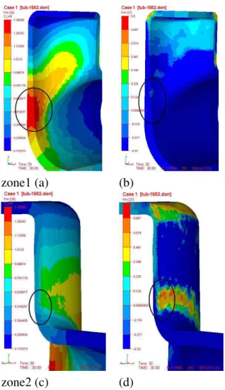
zone1 (a) (b)
zone2 (c) (d)
Figure 4: equivalent plastic strain (a-c) and triaxiality (b-d)
Table 3: Improved set of parameter
x α c b µf ri, µadh R n
mm WU WU WU WU mm WU
26.25 0.8 7 0.1 0.02 , 0.05 4 0.04
Figure 3 presents thickness repartition at the end of the process. A convenient thickness repartition is obtained coupled to law triaxiality and plastic strain level. The thickness ratio is now up to 0.93 avoiding excessive thinning.
4 Location of critical zones
Analysis of the the triaxiality and plastic strain iso-values show tow critical zones where a hight plastic strain is coupled to a positive triaxiality. Those zones are presented in figure 4.
Zone 1 is critical due to high level of plastic strain but triaxiality is rather small. Under−1/3 of triaxi-ality, damage is suppose to be frozen. In this zone a plastic instability is possible and can be determined by a localisation criterion. The second zone show a higher level of triaxiality. Coupled to a hight level of plastic strain this zone will probably develop damage. It can be noticed that only the outer face of the tube is submitted to this solicitation. Comparison of a local-isation criterion (MMFC,Swift) to a 3D computation coupled to a continuum damage model seems relevant to improve defect detection on the final part.
5 Conclusions
A simple and reliable numerical model has been pro-posed to simulate T-shaped tubes hydro-forming. Us-ing an iterative method an improved formUs-ing parame-ter set is proposed. Looking to plastic strain and triax-iality the detection of tow critical zones is performed. One of those zones show a hight level of triaxiality coupled to important plastic strain on the outer face of the tube. This phenomenon will drive to the appari-tion of defects. Improvement of the forming parame-ters can also be driven regarding to those defects. A 3D Continuum Damage model seems the reliable tool for the prediction of those defects. Some works are carried out in this way.
REFERENCES
[1] C.T.Kwan, C.Y.Lin, Y.S.Luo, W.B.Hu, and T.C.Jau. Die shape design for t-shaped tube hydroforming. Int. J. Adv. Manufacturing Technology, Vol.23:169–175, 2004.
[2] Kuang-Jua Fann and Pou-Yuan Hsiao. Optimization of load-ing conditions for tube hydroformload-ing. J. of Materials Pro-cessing Technology, Vol.140:520–524, 2003.
[3] G.Surdon and J-L.Chenot. Finit element calcula-tions of three-dimenssional hot forging. Int. conf. on numerical mmethods in Industrial Forming processes, Numiform’86:287–292, 1986.
[4] M.Jansson, L.Nilsson, and K.Simonsson. On strain locali-sation in tube hydroforming of aluminium extrusions. Jour-nal of Material and Processing Technology, Vol.195:3–14, 2008.
[5] W.J.Song, J.Kim, and B.S.Kang. Experimental and analyti-cal evaluation on flow stress of tubular matrial for tube hy-droforming simulation. J. Material Processing Technology, Vol.191:368–371, 2007.
[6] Y.M.Hwang, T.C.Lin, and W.C.Chang. Experiments on t-shaped hydroforming with counter punch. J. of Materials Processing Technology, Vol.192-193:234–248, 2007.