HAL Id: hal-03155866
https://hal.archives-ouvertes.fr/hal-03155866
Submitted on 2 Mar 2021HAL is a multi-disciplinary open access archive for the deposit and dissemination of sci-entific research documents, whether they are pub-lished or not. The documents may come from teaching and research institutions in France or abroad, or from public or private research centers.
L’archive ouverte pluridisciplinaire HAL, est destinée au dépôt et à la diffusion de documents scientifiques de niveau recherche, publiés ou non, émanant des établissements d’enseignement et de recherche français ou étrangers, des laboratoires publics ou privés.
Thermal energy storage systems for concentrated solar
power plants
Ugo Pelay, Lingai Luo, Yilin Fan, Driss Stitou, Mark Rood
To cite this version:
Ugo Pelay, Lingai Luo, Yilin Fan, Driss Stitou, Mark Rood. Thermal energy storage systems for concentrated solar power plants. Renewable and Sustainable Energy Reviews, Elsevier, 2017, 79, pp.82-100. �10.1016/j.rser.2017.03.139�. �hal-03155866�
1
Pelay, U., Luo, L., Fan, Y., Stitou, D., & Rood, M. (2017). Thermal energy storage systems for concentrated solar power plants. Renewable and Sustainable Energy Reviews, 79, 82-100. https://doi.org/10.1016/j.rser.2017.03.139
Thermal Energy Storage Systems for Concentrated Solar Power Plants
Ugo PELAY1, Lingai LUO1*, Yilin FAN1, Driss STITOU2, Mark ROOD31 Laboratoire de Thermique et Energie de Nantes, UMR CNRS 6607, Polytech' Nantes – Université de Nantes, La
Chantrerie, Rue Christian Pauc, BP 50609, 44306 Nantes Cedex 03, France
2 Laboratoire PROcédés, Matériaux et Energie Solaire (PROMES), UPR CNRS 8521, Rambla de la Thermodynamique,
Tecnosud, 66100 Perpignan, France
3 Department of Civil and Environmental Engineering, University of Illinois at Urbana-Champaign, 205 N. Mathews
Avenue, IL 61801, USA
Abstract
Solar thermal energy, especially concentrated solar power (CSP), represents an increasingly attractive renewable energy source. However, one of the key factors that determine the development of this technology is the integration of efficient and cost effective thermal energy storage (TES) systems, so as to overcome CSP’s intermittent character and to be more economically competitive. This paper presents a review on thermal energy storage systems installed in CSP plants. Various aspects are discussed including the state-of-the-art on CSP plants all over the world and the trend of development, different technologies of TES systems for high temperature applications (200 °C – 1000 °C) with a focus on thermochemical heat storage, and storage concepts for their integration in CSP plants.
TES systems are necessary options for more than 70% of new CSP plants. Sensible heat storage technology is the most used in CSP plants in operation, for their reliability, low cost, easy to implement and large experimental feedback available. Latent and thermochemical storage technologies have much higher energy density thus may have a bright foreground. New concepts for TES integration are also proposed, especially coupled technology for higher operating temperature and cascade TES of modularized storage units for intelligent temperature control.
The key contributions of this review paper consist of a comprehensive survey of CSP plants, their TES systems, the ways to enhance the heat and/or mass transfers and different new concepts for the integration of TES systems.
Keywords: Concentrated solar power (CSP), Thermal energy storage (TES), Integration, Thermochemical, Energy density
2 Abbreviations:
CLFR Compact Linear Fresnel collector CRS Central Receiver System
CSP Concentrated Solar Power
CST Concentrated Solar Thermoelectric DNI Direct Normal Irradiance
DSG Direct Steam Generation HCE Heat Collector Element HFC Heliostat Field Collector HTF Heat Transfer Fluid
IEA International Energy Agency LFR Linear Fresnel reflector PDC Parabolic Dish Collector PTC Parabolic Trough Collector M&O Maintenance and Operation n.a. not applicable
R&D Research and Development
SPT Solar Power Tower
STC Solar Tower Collector TES Thermal Energy Storage
3
1. Introduction
The use of renewable energy is essential today to decrease both the consumption of fossil resources and the production of carbon dioxide partly responsible for the greenhouse gas effect [1][2]. Among every renewable resources (e.g., wind, ocean, geothermal and solar), solar energy is showing encouraging promises due to the great quantities of solar irradiation flux arriving on earth.
Among various solar energy technologies, concentrated solar power (CSP) is particularly attractive due to its advantages in terms of high efficiency, low operating cost and good scale-up potential [3,4]. Solar energy is converted into electricity by means of a CSP plant composed of four main elements: a concentrator, a high temperature solar receiver, a fluid transport system and a power generation bloc (e.g., Rankine cycle, Stirling cycle). It is estimated by IEA that the CSP will contribute up to 11% of the global electricity production in year 2050 [5].
1.1. CSP technologies
A wide range of concentrating technologies exist; the most developed are parabolic trough collectors (PTC), linear Fresnel reflectors (LFR), solar power towers (SPT) and parabolic dish collectors (PDC), as summarized in Table 1. PTC plants use parabolic reflectors to focus sunlights on an absorber tube located on the focal line of the parabola. Reflectors and the absorber tube can move together to follow the sun from sunrise to sunset [5][6]. LFRs consist of curved reflectors on each side of an absorber tube. A recent design called compact linear Fresnel reflector (CLFR) uses two parallel reflectors for each mirror’s row, needing less area than a PTC to reach a given power output [8]. SPTs use heliostat field collectors (HFCs) to reflect and focus sunlights onto a central solar receiver located on the top of the tower. It is a relatively flexible technology because a variety of heliostat fields, solar receiver designs and heat transfer fluids (HTFs) could be used. PDCs concentrate sunlights on a focus point above a parabolic reflector. The reflector and receptor, tracks the sun. Besides these conventional types, CSP technology can also be combined with thermoelectric systems (i.e., concentrated solar thermoelectric) for direct electricity production without using a power cycle [8].
Table 1. Comparison between different CSP technologies [3,9,10]
1.2. Thermal energy storage
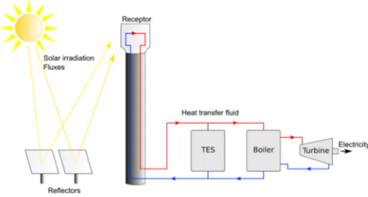
A major drawback of solar energy is its temporal intermittency. To overcome this problem, one solution is to use a backup system (energy hybridization) that burns fossil fuel or biomass. A second solution is to use a thermal energy storage (TES) system to store heat during sunshine periods and release it during the periods of weak or no solar irradiation (Figure 1).
Figure 1. CSP plant with a TES system
The development of an efficient and cost-effective TES system is crucial for the future of CSP technologies [14]. Economically, TES allows an increase in the duration of electricity production. Moreover, integrating a TES system in specific CSP configurations permits optimization of electricity resale and the CSP electricity production [15]. Indeed, as shown in Figure 2 [16], electricity prices vary during a day depending on demand. The solar intensity’s largest periods do not correspond to the electricity’s most expensive
4 periods. Adding a TES allows heat storage during high solar intensity periods and provides productions during high electricity cost periods.
Figure 2. Example of peak energy production and cost of energy for a CSP plant [16]
There are currently three kinds of TES systems available: sensible heat storage, latent heat storage and thermo-chemical heat storage [17,18]. Sensible heat storage systems are most mature. They are widely used in industrial plants, most notably in Spain within the “PS10” and “PS20” projects (2007 and 2009), the “Andasol 1” and “Andasol 2” plants (2008) and also in the USA (e.g., within “Solar One”, 1982) [18]. Latent heat storage allows large amounts of energy to be stored in relatively small volumes (high energy density) and is cost competitive. Among these techniques, thermochemical heat storage receives increasing attention. Two recent reviews were published, focusing on low to medium temperature (0 – 300 °C) thermochemical reactions pertaining to long-term sorption solar energy storage [19] and to chemical heat pump technologies [20]. Cot-Gores et al. [21] and Prieto et al. [22] also presented reviews on sorption and chemical reaction processes for TES application. Reaction candidates for medium or high temperature applications (250 – 800 °C) were listed by Felderhoff et al. [23].
1.3 Objectives of this paper
Based on the existing literature, we observe CSP plants worldwide and their characteristics (e.g., power, presence of a TES system, storage capacity) are partially (e.g., in [24]) presented, but a full description would be beneficial. In parallel, TES materials for CSP application need to be updated, especially those for thermochemical heat storage. Moreover, the issue of appropriate and new concepts for TES integration in CSP plants which is very important, is discussed here in more detail.
The present paper has therefore the following objectives:
• The most complete survey on CSP plants in operation, under construction and in project all over the world and on the trends of development in order to highlight the economic necessity of the integration of TES systems in CSP plants to compete with current energy production technologies. • A review on different technologies of TES systems and potential materials for CSP application, with
a special focus on thermochemical heat storage.
• A summary of storage concepts and integration configurations proposed in the literature
These contributions are important because the literature survey clearly shows the important role of TES systems in current and in future CSP plants. Moreover, if the selection of an adapted TES technology is the first step, its proper integration in a CSP plant is the next important step. Reviewing different storage concepts allows an overview on conventional TES integration configurations as well as innovative concepts recently proposed.
5
2. TES systems in CSP plants: the state-of-the-art
This section presents a literature survey on almost all CSP plants worldwide, including those already in operation, under construction or planned project. First, a large part of the data have been collected from the websites “cspworld.org” and “globalenergyobservatory.org”. Then a detailed research has also been made for each identified CSP plant on its proper website or related documents so as to find additional information. A statistical analysis of these data will show the general trends of CSP technologies such as the increasing plants’ average power or the necessity of TES systems for economic competitiveness.
To better illustrate the historical development, the surveyed CSP plants are divided into five groups: (i) 19 plants in operation with production began before year 2000 (named “before 2000” hereafter); (ii) 24 plants in operation with production started between year 2000 and 2010 (named “2000 to 2010”); (iii) 85 plants in operation with production began after 2010 (named “after 2010”); (iv) 35 plants now under construction and (v) 74 planned plants. The total number of samples thus reaches 237 CSP plants. Detailed data for every plant are provided in Table 1, 2 and 3 of the Data-in-Brief article [25].
Statistical analyses are provided about the purpose of plant, the average power and the storage/hybridization (Figure 3-5). It should be noted that despite all the efforts made by the authors, not all values are available for every CSP plant. In the current study, if a plant’s value was not available (n.a.) for a certain item, then that plant was eliminated from the analysis of that item. Table 2 counts the number of plants with known values used for each item of analysis compared to the total number of plants of each group.
Table 2. Number of samples for each item of analysis 2.1. Purpose of plants
Figure 3 shows different purposes of CSP plants (commercial, demonstration or Research & Development) and their respective percentage for each group of plants. CSP plants with a commercial purpose always represent the vast majority. Research and development (R&D) used to be the second biggest purpose for plants in operation. However, their installation decreases gradually in recent years. No plant is planned in the future specially for R&D purpose, indicating that CSP technologies have become relatively mature and readily available for commercialization. Meanwhile, the proportion of plants built for a demonstration purpose remains almost constant since 2010.
Figure 3. Purposes of CSP plants and their respective percentage
2.2. Types of CSP technology
Figure 4 shows the historical evolution of used CSP technologies. PTC and SPT are the most used technologies for plants in operation. Meanwhile, trends also show that there will be a higher ratio of SPT for CSP plants in project. LFR represents the third most frequently used CSP technology. PDC is a relatively young technology with no plants in activity. Nevertheless, it represents 7-9% of plants under construction and planned, making it a non-negligible technology in the future.
6
2.3. Average power of CSP plants
Figure 5.a shows the historical evolution of CSP plant’s average power. The average power has increased by a factor of 6 from about 21 MWelect for power plants in operation before 2000 to more than 120 MWelect for planned power plants. One reason for this increasing average power is the change of the purpose of the plants since more than a quarter of plants in operation is related to a demonstration or a R&D purpose (Figure 3). These plants were not built for electricity sale thus produced generally a few megawatts. Plants under construction and planned are more commercial plants of higher power output, including the 2000 MWelect facility for the planned “TuNur” plant in Tunisia.
Figure 5.a. Evolution of average power of CSP plants Figure 5.b. Percentage of hybridization for CSP plants
Figure 5.c. Presence of TES system in CSP plants Figure 5.d. Evolution of storage capacity for TES systems in CSP plants
2.4. Hybridization
Sometimes CSP plants are hybridized with a backup system that provides supplementary energy source when solar intensity is not adequate and when a quick response is needed [26]. Fossil fuels (i.e., coal, natural gas or diesel) are the most commonly used backup energy sources while biomass (e.g., “Borges solar”, Spain, in operation) or solar photovoltaic (e.g., “Ashalim csp plant”, Israel, planned) are occasionally used. Natural gas remains as the preferential fuel for hybridization [27]. With the hybridization of the backup system, the continuous electricity production of the CSP plant can generally be guaranteed which increases the plant global efficiency [26].
The percentage of hybridization for each group of CSP plants is shown in Figure 5.b. The use of hybridization systems is globally decreasing. This is mainly due to the increasing price of fossil fuels. Another possible reason is the increasing use of TES systems that will be discussed later. In fact, very few plants operate only with solar energy. A TES system and/or a hybridization system are always necessary to be added into a CSP plant to overcome the temporal variability of solar energy. However, care must be taken with these results, particularly for plants under construction and planned because of missing data.
2.5. Thermal storage
Figure 5.c indicates the percentage of plants implementing a TES system. About half of the plants (47%) currently in operation integrate a TES system. There is a notable increase in the use of TES systems for plants under construction (72%) and planned (77%). This increase can be partially explained by the technological progress and advancements achieved in storage systems and the necessity to install such systems to be economically competitive.
Sensible storage is the dominant TES technology used in CSP plants. It is the most developed technology that has been studied, tested and installed. Ruths tank (also called steam accumulator) is the only alternative for limited storage capacity installed in a CSP plant (e.g., “Augustin Fresnel”, France, in operation, 0.25 hour of storage; “Alba Nova”, France, under construction, 1 hour of storage). In the meantime, it is advisable to put in perspective these data and particularly those relating to plants under construction and planned, because in a certain number of cases the planned storage mode is not known.
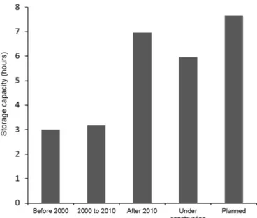
7 Figure 5.d shows the evolution of the average storage capacity, represented by the time during which the plant is able to work with the energy provided by the TES system. The average storage capacity has steadily increased, from 3 hours to more than 7 hours for plants currently in project. As it will be possible to see in next parts, research on TES have developed more efficient and less expensive technologies. Today, plant stakeholders would benefit to install a TES to increase the profitability of their facilities. Many plants under construction or planned intend to do mass production of electricity and require a TES system large enough for continuous production during periods of low solar intensity. In addition, a number of plants built before 2010 have low storage capacity TES systems because their goal is to investigate the heat and mass transfer characteristics and validate their analytical/numerical models but not to produce electricity at a lower cost.
2.6. Short summary
Table 3 summarizes the state of the art of CSP plants in operation and future trends (plants under construction and planned). CSP plants have a great future, indicated by the increases in the number, the average power output per plant and proportion of commercial plants. To allow plants to operate and to be economically competitive, a hybridization system and/or a TES system is necessary. Hybridization systems used to be a standard option to increase the dispachability of CSP plants. However, they usually consume fossil fuels with increasing costs and high CO2 emissions. In the meantime, TES technologies have no such problems and could become an alternative or even a replacement. A quick geographical analysis of the planned CSP plants shows that USA, Italy and Chile are the leading countries for CSP installation. These countries are not traditional oil producers and tend to use TES systems instead of fossil source backups. Another trend is that even if several storage technologies are available, sensible storage is almost the only choice. However, we will see in the next section that other types of storage have great advantages and deserve to be studied.
Table 3. Summary for TES systems in CSP plants
3. TES technologies for CSP application
As we saw in the above section, the integration of a TES system is necessary, which allows a plant to operate more stably and to meet the demands of the power grid. Therefore, selecting appropriate TES technologies and designing highly efficient TES systems are becoming the research focus. In a recent review [28], Tian and Zhao summarized main criteria to be considered in the design of a solar TES system. Aspects were proposed, including technical properties, economic costs and environmental impacts. Among influencing factors, the most expected features of a TES system are a high energy density to reduce the necessary amount of materials and the occupancy space, reliable mechanical and chemical stability and enhanced heat transfer during charges or discharges. Meanwhile, the cost of TES system (including storage materials, reservoirs, heat exchangers) is also an important criterion which directly determines the payback period of the investment. Finally, storage materials should be environmental friendly, low corrosive, complete reversible and non- or low-flammable.
As previously mentioned, TES technologies available for CSP application are classified into sensible, latent and thermochemical categories. Sensible heat storage is currently the most commonly used
8 technology (Table 3), with a large number of low-cost materials available [29–31]. However, the lowest energy density of this technology results in large size of TES systems. Latent heat storage technology has a higher energy density, but a poor heat transfer performance due to very low thermal conductivity of the materials. Thermochemical storage has the highest storage energy density, thus seems to be the most promising technology for the future. Nevertheless, problems such as more complex design of reactors, low chemical stability, poor heat and mass transfers and degraded performance over charge/discharge cycles hinder its real application in CSP plants [22].
Different technologies to store thermal energy for CSP application (between 200°C and 1000°C) are described below. Emphasis is put on recent advances in thermochemical heat storage technology, which is under-developed but has a great potential.
3.1. Sensible heat storage
In sensible heat storage, thermal energy is stored/released by raising/decreasing the temperature of a storage material. It is a pure physical process without any phase change during charge or discharge. Therefore, the amount of heat stored depends on the product of the mass, specific heat, and temperature variation of the storage material. In addition to the density and the specific heat of the storage material, other properties are also important for sensible heat storage: operating temperature, thermal conductivity and diffusivity, chemical and thermo-chemical stability of the materials and the cost [17]. The major drawback of sensible heat storages is their limited energy density (between 60 kWht.m-3 for sand (200-300°C), rock, mineral oil and 150 kWht.m-3 for cast iron (200-400°C) [32]) which makes storage units particularly large. Moreover, the storage units should be designed in a proper manner for heat discharge at relatively constant temperatures.
Sensible heat storage materials in solid and liquid form are the most studied materials and are at an advanced stage of development. Solid materials generally have a wide range for possible temperature variation (200 – 1200 °C), with high thermal conductivity (from 1 to 40 W.m-1.K-1) and relatively low cost (0.05 – 5 $.kg-1). Concrete and castable ceramics are intensively studied which have good characteristics (0.05 $.kg -1 and good thermal conductivity: 1.5 W.m-1.K-1 [32]) to be used as a solid heat storage materials [33]. In order to improve the stability of concrete at high temperature, a new concrete with polypropylene fibers was specially developed [29][30]. Other solid materials such as graphite (e.g., “Lake Cargelligo” in Australia) and pebble stone (e.g., “Airlight Energy Baha Plant” in Morocco) are also occasionally used, as listed in Table 1 of [25]. A comprehensive list of solid sensible heat storage materials for CSP applications and their main characteristics are provided by Gil et al. [17].
Instead of using new manufactured materials, industrial waste or or by-product materials (i.e., asbestos containing wastes, bischofites, slags, etc.) [36,37] and low cost materials (i.e., sand, rocks) are also available [38,39]. Their adapted thermal properties, low cost and strong environmental and societal benefits (reduced landfilled waste amounts and the greenhouse emissions) make them good candidates for TES systems at high temperature [36].
Liquid materials are also widely used in CSP plants. Molten salts are considered as one of the best materials for CSP application [17,29–31] owning to their features including excellent thermal stability at high temperatures, low vapor pressure, low viscosity, high thermal conductivity, flammability and non-toxicity. The two leading candidates are “solar salt” (60% NaNO3 and 40% KNO3) used in “Archimede”, Italia, in activity and “MSEE/CatB”, USA, in activity, and “HitecXL” (48% Na(NO3)2, 7% NaNO3 and 45% KNO3 [40]). HitecXL was tested in “PSA plant”, Spain and “Themis plant”, France. It was developed as a second option for
9 Hitec (40% NaNO2, 7% NaNO3 and 53% KNO3, melting point at 142 °C) [29][40]. A new series of ternary salts mixtures was proposed with ultra-low melting temperatures at 76 °C, 78 °C or 80 °C, preventing the solidification of salt and making the TES system much easier to manage [30,41]. Mixtures of salts consisting of KNO3, LiNO3 and Ca(NO3)2 showed reduced viscosity by a factor of 5 compared to that of commercial synthetic oils or molten salts. Such eutectic salts whose melting temperatures points are also below 100 °C have also been reported by Wang et al. [42].
Effective solutions to increase the energy density of sensible heat storage materials like molten salts consist in adding encapsulated PCMs [43–45] or nanoparticles [46–49]. Encapsulation means the coating of PCM particles with a protecting shell to improve the chemical stability and to prevent individual particles from coalescing with one another during melt/freezing cycles. Adding encapsulated PCMs in sensible materials can be considered as a new coupled technology, as will be detailed in the later section of this paper. Adding nano-particles in sensible storage materials will increase its specific heat. Andreu-Cabedo et al. [47] showed that the specific heat of a solar salt can be increased by 25.03% by adding 1 wt.% of silica nanoparticles (SiO2).
Other liquid materials are also used in CSP plants. For example, oils have been used in “Dahan Power Plant” in China. Liquid sodium having a very high thermal conductivity (71 W.m-1.K-1)) is used in “PSA SSPS-CRS plant” in Spain. However, additional safety measures are necessary due to their unstable nature caused by their high vapor pressure [30] which may cause serious security problems. Liquid sensible heat storage materials for CSP applications and their main characteristics are described by Gil et al. [17].
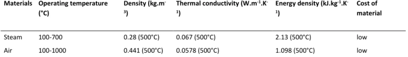
Gaseous materials have been used in CSP plants in operation such as compressed air or steam as storage media (e.g., “Exresol-1” “Planta Solar 20” and “Planta Solar 10” in Spain), as shown in Table 1 of [25]. Their main physical properties are shown in Table 4. The advantages of using gaseous materials are their availability, low cost, non-toxicity and wide range of operating temperature. The disadvantages of using gaseous materials are their low thermal conductivity and very low energy density. Even if the gas is stored compressed, the large volume of the reservoirs makes this storage option very challenging for CSP plants with high power output.
Table 4: Gaseous materials for sensible heat storage 3.2. Latent heat storage
In latent heat storage, thermal energy is stored/released by a material while changing its phase at a constant temperature. It is also a pure physical process without any chemical reaction during charge or discharge. The amount of heat stored is generally the latent heat of phase change (latent heat of fusion for a solid-liquid transition and latent heat of vaporization for a liquid-vapor transition).
Phase change materials (PCM) for latent heat storage have the advantage to charge or discharge in a narrow temperature range, close to their phase change temperature. They also have higher energy densities owing to their high phase change latent heat (between 27 kJ.kg-1 for TRIS ((NH
2)C(CH2OH)3) and 790 kJ.kg-1 for the eutectic salt (80.5%LiF-19.5%CaF
2) compared to sensible heat storages. The phase change concerning thermal storage could be either solid-liquid or solid-solid, because volume and pressure are roughly constant.
The main drawback of PCMs is their low thermal conductivity (usually 0.2 – 0.8 W.m-1.K-1 [20,50]), resulting in very slow charge and discharge processes [51]. Several approaches may be considered to enhance their heat transfer, including using transportable PCMs [52] (detailed in section 4.2 of this paper), adding thermal conductivity promoters into pure PCMs and using high conductivity PCMs made of metal alloys [53–
10 55]. One of the common additives for PCMs is the graphite. The thermal conductivity of PCM/graphite composites could reach 5 to 10 W.m-1.K-1 depending on the amount of graphite added [56]. Other thermal conductivity promoters are also investigated, such as insertion of a metal matrix or foam [57–60], fins [61], dispersion of high conductivity particles [62], micro-encapsulation of the PCMs [63–67] or special designs of TES system with embedded heat pipes [68] or finned heat pipes [69]. Recent advances on the geometrical configurations of TES systems using PCMs are reviewed by Mao [70] and the shell materials used in the encapsulation of PCMs could be found in the review of Jabob and Bruno [71]. PCMs made of metal alloys (i.e., Mg-Zn-Al) have the advantages such as high thermal conductivity (around two orders of magnitude higher than that of molten salts) and good thermo-chemical stability. However, their high price (2-3 $/kg) is an obstacle to be used in large scale TES [54].
Inorganic and organic substances with potential use as thermal storage material at high temperature and their physical-thermal properties are listed by Gil et al. [15] and Sharma et al. [65]. Melting temperature of these PCMs generally varies between 100 and 900 °C. Materials whose phase change temperatures are the lowest (100 – 300 °C) can be used as TES systems for PTC, LFR and PDC. Materials with higher phase change temperatures (> 400 °C) are suitable to be used in SPT or PDC whose operating temperature goes up to 600 °C or 1500 °C, respectively [3][8].
3.3. Thermochemical heat storage
Different from sensible or latent heat storages, thermochemical TES technology is based on reversible chemical reactions, which are characterized by a change in the molecular configuration of the reactants (combination or decomposition). Solar heat is used to drive an endothermic chemical reaction, and then stored in the form of chemical potential. During the discharge, the stored heat can be recovered by the reversed exothermic reaction, sometimes by adding a catalyst. The advantages of thermochemical storage relies on their high energy density (up to 10 times greater than latent storage [14]) and the indefinitely long storage duration at ambient temperature. As a result, it is a very attractive option and fairly economic competitive [29].
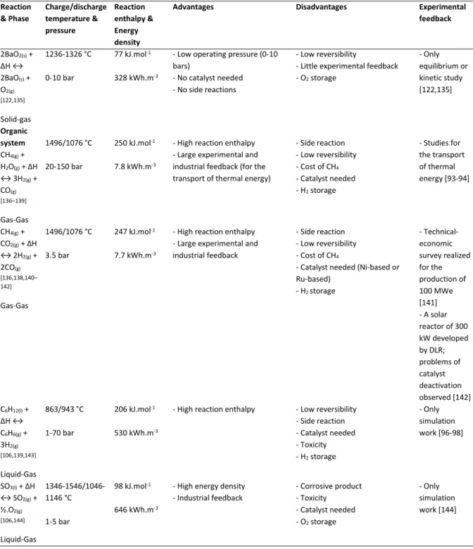
Metallic hydrides, carbonates system, hydroxides system, redox system, ammonia system and organic system can be used for thermochemical heat storage at medium or high temperatures (300 – 1000 °C) [14]. Table 5 groups these reactions with their mains characteristics, advantages/disadvantages and experimental feedback with corresponding references. Some reactions (e.g., PbCO3/PbO; CaCO3/CaO; (CH4+CO2)/(CO+H2); C6H12/C6H6; NH3/N2; BaO2/BaO; (CH4+H2O)/(CO+H2)) suffer from the problem of incomplete reversibility, which is a key drawback because their storage capability gradually decreases after cycles of operation.
Table 5. Main reactions used in high temperature thermochemical heat storage [14], [17], [33], [84–88]
Candidate reactions possessing good reversibility include Co3O4/CoO, SO3/SO2 and particularly TiH2/Ti. They have good potential for CSP application but more experimental feedback is needed [72]. Mg/MgH2 and NH4HSO4/(NH3+SO3) have shown to have good reversibility by intensive experimental tests but how to store the reaction products remains as a technical barrier. Indeed, these products in gaseous form (H2, SO3 and NH3) need to be compressed and stored in large tanks, implying higher installation and operation costs. Some alternative solutions were proposed and tested, such as the storage of H2 with metals hydrides at low temperatures [73] or by adsorption [74] but additional costs seem inevitable. Hydration/dehydration
11 of CaO/Ca(OH)2 is another promising candidate with numerous expected features (e.g., good reversibility, low operating pressure, low price and no-toxicity of the product and large experimental feedback). Meanwhile, technical problems such as low thermal conductivity, agglomeration and sintering still remain to be solved.
Common drawbacks of materials used for thermochemical storage are low thermal conductivity which slows the heat transfer and low permeability which reduces the mass transfer. Many studies are devoted to the material properties and reactor designs so as to enhance the mass transfer during combination and also to enhance the heat transfer during decomposition [75,76]. The latest advancements and proposed methods are reviewed by Aydin et al. [77]. The available solutions are the construction of matrix [78] in the reactant part or the melting of the reactant with additives (e.g., expended graphite matrix [79,80], aluminum foam [81], cobalt/cobaltous oxide based honeycombs [82]). Roßkopf et al. [83] also reported that power bed properties and thermal stability of thermochemical materials can be improved by adding nanoparticles (i.e., SiO2).
3.4. Short summary
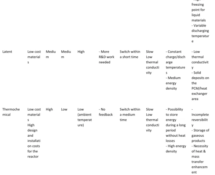
Table 6 summarizes main characteristics of different TES technologies and key features.
Table 6. Summary for different TES technologies
4. Concepts for TES integration
Beyond choosing the suitable TES technology for CSP application, the TES system must be coupled in a proper way with the power generating cycle (e.g., Rankine cycle). Pertinent concepts that integrate TES system and the power generating cycle remain as one of the key issues for the actual application of TES technology. This section will review the commonly proposed concepts for TES integration and compare their advantages and disadvantages. Special attention is given to new trends of integration concepts, especially when more than one TES technologies are envisaged.
4.1. Classification
Based on the motion state of storage materials during charge or discharge, the concepts for TES integration can be broadly classified into two concepts: active concept and passive concept. In active storage systems, the storage medium itself flows to absorb (charge) or release (discharge) heat by forced convection. Contrarily in passive storage systems, the storage medium (often solids) is kept motionless and heated or cooled by the circulation of another heat transfer fluid (HTF).
Active systems can be subdivided into direct and indirect systems. In an active direct system, the storage medium itself also serves as the HTF used for the solar field (Figure 6a). During charge phase, the HTF is directly stored in a hot tank located at the exit of the solar field. During discharge phase, the hot HTF in the hot tank is pumped through the power cycle and then stored in a cold tank at the entrance of the solar field for the next charge/discharge cycle [145]. This concept needs no heat exchanger between HTF and storage materials. But suitable storage materials (molten salts or steam) are required because they should meet the requirements to be a good HTF and a good storage material at the same time.
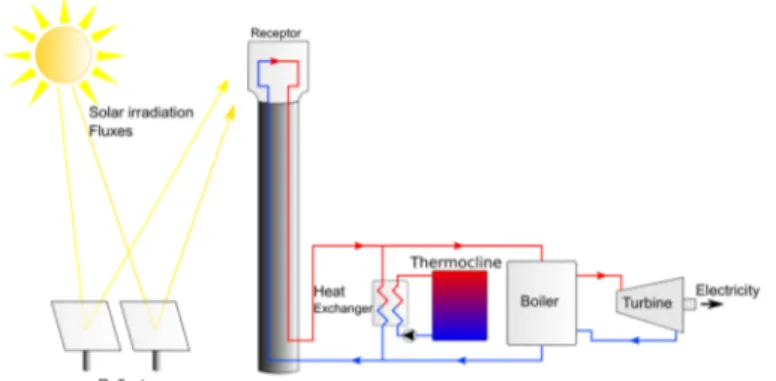
12 In active indirect systems, the HTF and the storage medium are different. A typical active indirect concept is shown in Figure 6b, with two separate tanks for the storage. During the charge phase, the storage material in the cold tank is pumped through a heat exchanger where it is heated by the HTF, and then stored in the hot tank. During the discharge phase, the flow direction of storage material is reversed to release the heat to the HTF. In this manner, hot and cold materials are separately stored. An alternative to two tanks concept is using a single tank (Figure 6c) where hot materials are stored on the top while the cold materials on the bottom. They are separated because of the temperature stratification. The zone between the hot and cold fluids is called the thermocline. Usually a filler material (e.g., quartzite rock, sand, concrete, industrial waste) is added in the tank to enhance the thermocline effect and to reduce the needed quantity of storage materials. Therefore, it is about 35% cheaper than two tanks systems [17]. Some studies showed that filled thermocline with encapsulated PCM was also appropriate [45]. One of the key factors for highly efficient thermocline storage is maintaining the temperature stratification by a controlled procedure of charge and discharge and by appropriate methods or devices to avoid mixing. The filling configuration of filler materials in the storage tank is certainly a key point to be considered. Wu et al. [146] studied the thermocline behaviors of four typical concrete structures during the discharging process, including the channel-embedded structure, the parallel-plate structure, the rod-buddle structure and the packed-bed structure. They found that the packed-bed structure seemed to have better thermal performance [146].
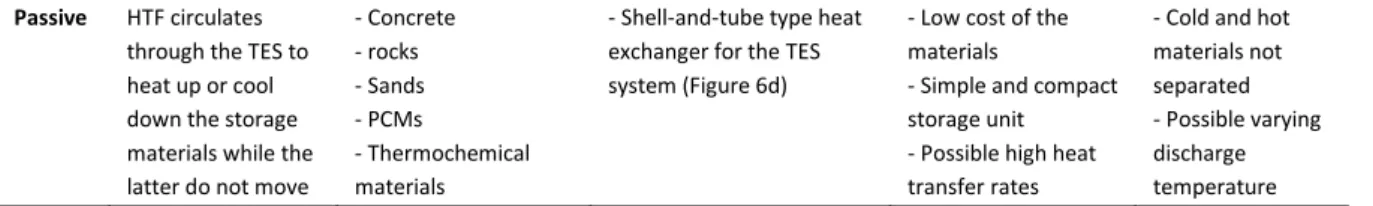
In a passive storage system, HTF circulates through the TES system to heat up or cool down the storage materials kept still inside. In the case of sensible storage using concrete, the TES system usually contains a tubular heat exchanger (Figure 6d) integrated into storage materials, forming a compact heat storage-exchanging unit. The high thermal conductivity of materials and the good contact between the concrete and the tubes enable high heat transfer rates. However, the discharge temperature may vary when concrete is cooled down. This problem may be overcome by using PCMs and thermochemical materials, but with lower heat transfer rates.
Table 7 summarizes the concepts for TES integration in CSP plants, principles, storage materials, examples of system integration, as well as their advantages and disadvantages.
Figure 6.a. Active direct concept for TES integration
Figure 6.b. Active indirect concept for TES integration, two tanks
Figure 6.c. Active indirect concept for TES integration, single tank
Figure 6.d. Passive concept for TES integration
13 4.2. New trends for TES integration
Based on recent literature, several new trends for TES integration may be observed: (i) coupled TES technologies for possible higher operating temperature; (ii) cascade concept with modularized units; and (iii) mechanical circulation of granular particles.
Coupled systems using two types of storage technologies (e.g., latent, sensible-thermochemical, sensible-sensible) allow increased storage capacity, reduced delay between charge and discharge and increased power bloc working temperature (till 1400°C [147]). High operating temperature for CSP will increase the CSP’s efficiency for cheaper electricity production. However, the TES design, operation and control become more complex with higher associated costs.
A good example is the coupled chemical-thermal solar power system [147], as shown in Figure 7. The CSP system couples a thermal and a chemical energy pathway. The thermal pathway utilizes a HTF to collect
concentrated sunlights as thermal energy at medium or high temperature (<700°C) and to transfer this energy to a thermal-to-electric power cycle.In parallel, the chemical pathway uses a redox material (e.g., Co3O4/Co3O, BaO2/BaO (Table 5)) which undergoes direct reduction in the receiver to store the solar energy as chemical potential. This redox material is then oxidized at very high temperatures (1400°C) in the power cycle in series with the thermal pathway heat exchanger. This thermal-chemical coupling allows the power cycle to perform at very high temperature, increasing its global solar-to-electric conversion efficiency. However, the receiver design seems complex as it also serves as a reactor for chemical reaction.
Figure 7. Example of coupled chemical-thermal solar power system [147]
Another example of a coupled TES system is the three-part thermal energy storage system for direct steam generation (Figure 8) [148]. The storage system is composed of three blocks, two are filled with sensible materials (concrete) for preheating and superheating and an intermediate one with implementing a PCM material (NaNO3) to evaporate/condensate the HTF. The compact design is particularly adapted for direct steam generation.
Figure 8. Example of coupled sensible-latent three-part thermal energy storage system for direct steam generation [148]
Azanganeh et al. [149] proposed a coupled latent-sensible thermocline TES system, as shown in Figure 9. It combines rocks in the main body and encapsulated PCMs placed on the top of the tank, with the purpose of maintaining constant outflow temperature. Their investigation indicated that only a small amount of PCM (1.33% of the total volume) was sufficient to achieve outflow temperature stabilization around the PCM’s melting point [149].
Adding encapsulated PCMs in sensible materials as a new trend is intensively investigated [43–45]. Cingarapu et al. [43] showed that adding 10 vol% of coated Zn particles over the base of chloride salt eutectic augments from 15% to 34% the volumetric storage capacity depending on the cycling temperature range (ΔT= 50°C – 100°C) .
14 The second trend of TES integration is the cascade of modularized TES units. Conventional TES systems used to be made in one block. Novel TES systems now consist of several blocks to reduce thermal inertia of the systems and easy control of the HTF’s temperature passing through. The main disadvantages of the cascade concept are their more complicated design than a single unit and their higher costs due to the use of several heat exchangers, tanks and regulation systems.
One example of this trend is the cascade latent heat storage system [150], using different phase change materials with different temperatures of phase change (306 – 380 °C) (Figure 10). Therefore, it is possible to store energy within a wide temperature range or to discharge at a constant temperature. However, the final design is complicated and the low thermal conductivity of PCMs needs to be improved.
Figure 10. Example of a cascade latent heat storage system [150]
Another example of cascade TES system for Direct Steam Generation (DSG) is shown in Figure 11 [151]. The storage unit is composed of several blocks of sensible material (e.g., concrete, molten salt, sand). The steam can pass through one or several blocks depending of its temperature. The main advantage of this system is the reduced thermal inertia of the TES system by dividing one storage block into three. However, the costs for construction and for the associated control system are inevitably higher than those for a single block TES system.
Figure 11. Example of a solar energy system [151]
Other new concepts proposed involve mechanical displacement of solid PCM or chemicals reactants [152][153]. A good example of this type of systems is a CSP system using fluidized-bed technology for thermal energy conversion and solid particles for thermal energy storage [154,155], as shown in Figure 12. This system uses granular particles as both HTF and storage materials. Solid granular particles are moved from the cold tank to the solid-particle receiver by a bucket lifter system. After absorbing the solar heat and reaching a very high temperature (> 1000°C), they then fall into the hot silo used as TES system by gravity. The stored heat could be discharged to the working fluid of the power generation cycle by circulating the granular particles through the fixed bed heat exchangerThe mains advantages of this system are the high stability of particles at high temperature and their low cost. However, its application in large-scale is still challenging and needs to be further tested.
Figure 12. Example of a pressurized fluidized bed for an air-Brayton gas-turbine combined CSP system [154]
Besides all these new concepts, researchers [156] also proposed to use an intermediate HTF to reduce the HTF pressure in the heat exchanger. But the number of heat exchangers will increase, leading to increased costs. Table 8 summarizes these new concepts proposed in the literature for TES integration with their advantages and disadvantages.
15
5. Conclusion
This work provides an extensive review on the thermal energy storage systems (TES) in CSP plants worldwide. The state-of-the-art for CSP plants, different TES technologies and the concepts for their integration in CSP plants are discussed. The major conclusions may be summarized as follows.
• CSP technology is already mature and readily available for commercialization, indicated by the increasing number of commercial CSP plants that are currently under construction or planned and by their increasing average power output.
• TES systems seem indispensable for the future more powerful CSP plants, for the latter to be more economically competitive and more dispatchable. Progress in TES technologies permit the increased storage capacity of their TES systems.
• A vast majority of CSP plants in operation use sensible heat storage, for their reliability, low cost and large experimental results obtained. The low energy density makes them more suitable for small or moderate power plants but less competitive for large-scale powerful CSP plants.
• Technologies of latent storage and thermochemical storage have much higher energy density, thus will have a bright foreground.
Some technological barriers remain to be overcome for latent and thermochemical storage, which are also the key issues of current research and development:
• To enhance the thermal conductivity of PCMs and thermochemical materials;
• To remove solid deposits that form at the exchange surfaces between PCM and the HTF; • To enhance the heat and mass transfers during thermochemical reactions;
• To reduce the transition time during the switch from charge to discharge (and vice versa); • To propose suitable and adaptive concepts for TES integration in CSP plants; and
• To design modularized TES units and their appropriate assembling and management.
Acknowledgement
Authors would like to thank the financial support of the French “Agence National de la Recherche” within the project In-STORES (ANR-12-SEED-0008).
16
References
[1] Ervin G. Solar heat storage using chemical reactions. J Solid State Chem 1977;22:51–61. doi:10.1016/0022-4596(77)90188-8.
[2] International energy agency. World energy outlook. 2013.
[3] Zhang HL, Baeyens J, Degrève J, Cacères G. Concentrated solar power plants: Review and design methodology. Renew Sustain Energy Rev 2013;22:466–81. doi:10.1016/j.rser.2013.01.032.
[4] Desideri U, Campana PE. Analysis and comparison between a concentrating solar and a photovoltaic power plant. Appl Energy 2014;113:422–33. doi:10.1016/j.apenergy.2013.07.046.
[5] Internationnal energy Agency. Technology Roadmap: Concentrating Solar Power n.d. doi:10.1787/9789264088139-en.
[6] Llorente García I, Álvarez JL, Blanco D. Performance model for parabolic trough solar thermal power plants with thermal storage: Comparison to operating plant data. Sol Energy 2011;85:2443–60. doi:10.1016/j.solener.2011.07.002.
[7] Müller-steinhagen H. Concentrating solar power : A review of the technology. Q R Acad Eng 2004.
[8] Barlev D, Vidu R, Stroeve P. Innovation in concentrated solar power. Sol Energy Mater Sol Cells 2011;95:2703– 25. doi:10.1016/j.solmat.2011.05.020.
[9] Internationnal energy Agency. Technology Roadmap Concentrating Solar Power. 2010.
[10] Agalit H, Zari N, Maalmi M, Maaroufi M. Numerical investigations of high temperature packed bed TES systems used in hybrid solar tower power plants. Sol Energy 2015;122:603–16. doi:10.1016/j.solener.2015.09.032. [11] Llc L, Group C. Assessment of Parabolic Trough and Power Tower Solar Technology Cost and Performance
Forecasts Assessment of Parabolic Trough and Power Tower Solar Technology Cost and Performance Forecasts 2003.
[12] Ortega JI, Burgaleta JI, Téllez FM. Central Receiver System Solar Power Plant Using Molten Salt as Heat Transfer Fluid. J Sol Energy Eng 2008;130:24501. doi:10.1115/1.2807210.
[13] Pitz-Paal R, Dersch J, Milow B, Téllez F, Ferriere A, Langnickel U, et al. Development Steps for Parabolic Trough Solar Power Technologies With Maximum Impact on Cost Reduction. J Sol Energy Eng 2007;129:371. doi:10.1115/1.2769697.
[14] Pardo P, Deydier a., Anxionnaz-Minvielle Z, Rougé S, Cabassud M, Cognet P. A review on high temperature thermochemical heat energy storage. Renew Sustain Energy Rev 2014;32:591–610. doi:10.1016/j.rser.2013.12.014.
[15] Guédez R, Spelling J, Laumert B. Reducing the Number of Turbine Starts in Concentrating Solar Power Plants Through the Integration of Thermal Energy Storage. J Sol Energy Eng 2015;137. doi:10.1115/1.4028004. [16] Sioshansi R, Denholm P. The Value of Concentrating Solar Power and Thermal Energy Storage. Sustain Energy
2010;1:173–83.
[17] Gil A, Medrano M, Martorell I, Lázaro A, Dolado P, Zalba B, et al. State of the art on high temperature thermal energy storage for power generation. Part 1—Concepts, materials and modellization. Renew Sustain Energy Rev 2010;14:31–55. doi:10.1016/j.rser.2009.07.035.
[18] Medrano M, Gil A, Martorell I, Potau X, Cabeza LF. State of the art on high-temperature thermal energy storage for power generation. Part 2-Case studies. Renew Sustain Energy Rev 2010;14:56–72. doi:10.1016/j.rser.2009.07.036.
[19] N’Tsoukpoe KE, Liu H, Le Pierrès N, Luo L. A review on long-term sorption solar energy storage. Renew Sustain Energy Rev 2009;13:2385–96. doi:10.1016/j.rser.2009.05.008.
[20] Wongsuwan W, Kumar S, Neveu P, Meunier F. A review of chemical heat pump technology and applications. Appl Therm Eng 2001;21:1489–519.
17 [21] Cot-Gores J, Castell A, Cabeza LF. Thermochemical energy storage and conversion: A-state-of-the-art review of the experimental research under practical conditions. Renew Sustain Energy Rev 2012;16:5207–24. doi:10.1016/j.rser.2012.04.007.
[22] Prieto C, Cooper P, Fernandez AI, Cabeza LF. Review of technology: thermochemical energy storage for concentrated solar power plants. Renew Sustain Energy Rev 2016;60:909–29. doi:10.1017/CBO9781107415324.004.
[23] Felderhoff M, Urbanczyk R, Peil S. Thermochemical heat storage for high temperature applications-A review. Green 2013;3:113–23.
[24] CSP World. CSP World Map 2015. http://www.csp-world.com/cspworldmap.
[25] Pelay U, Luo L, Fan Y, Stitou D, Rood M. Technical Data of concentrated solar power plants in operation, under construction and planned_submitted. Data Br 2017.
[26] Suresh NS, Thirumalai NC, Rao BS, Ramaswamy MA. Methodology for sizing the solar field for parabolic trough technology with thermal storage and hybridization. Sol Energy 2014;110:247–59. doi:10.1016/j.solener.2014.09.020.
[27] El Gharbi N, Derbal H, Bouaichaoui S, Said N. A comparative study between parabolic trough collector and linear Fresnel reflector technologies. Energy Procedia 2011;6:565–72. doi:10.1016/j.egypro.2011.05.065.
[28] Tian Y, Zhao CY. A review of solar collectors and thermal energy storage in solar thermal applications. Appl Energy 2013;104:538–53. doi:10.1016/j.apenergy.2012.11.051.
[29] Pilkington Solar International GmbH. Survey of Thermal Storage for Parabolic Trough Power Plants. Cologne, Germany: 2000.
[30] Zhao CY, Wu ZG. Thermal property characterization of a low melting-temperature ternary nitrate salt mixture for thermal energy storage systems. Sol Energy Mater Sol Cells 2011;95:3341–6. doi:10.1016/j.solmat.2011.07.029.
[31] Zhao CY, Zhou D, Wu Z. Heat transfer enhancement of phase change materials (PCMs) in low and high temperature thermal storage by using porous materials. 14th Int. Heat Transf. Conf., Washington: 2010, p. 435– 41.
[32] Fernandes D, Pitié F, Cáceres G, Baeyens J. Thermal energy storage: “How previous findings determine current research priorities.” Energy 2012;39:246–57. doi:10.1016/j.energy.2012.01.024.
[33] Lovegrove K, Luzzi A, Kreetz H. A solar-driven ammonia-based thermochemical energy storage system. Sol Energy n.d.;67:309–16.
[34] Tamme R, Steinmann W, Laing D. Thermal energy storage technology for industrial process heat applications. Proc. Int. Sol. Energy Conf., 2005, p. 417–22.
[35] Martins M, Villalobos U, Delclos T, Armstrong P, Bergan PG, Calvet N. New Concentrating Solar Power Facility for Testing High Temperature Concrete Thermal Energy Storage. Energy Procedia 2015;75:2144–9. doi:10.1016/j.egypro.2015.07.350.
[36] Gutierrez A, Miró L, Gil A, Rodríguez-aseguinolaza J, Barreneche C, Calvet N, et al. Advances in the valorization of waste and by-product materials as thermal energy storage (TES) materials. Renew Sustain Energy Rev 2016;59:763–83. doi:10.1016/j.rser.2015.12.071.
[37] Ortega JI, Calvet N, Gil A, Rodríguez-aseguinolaza J, Faik A, D’Aguanno B. Thermophysical characterization of a by-product from the steel industry to be used as a sustainable and low-cost thermal energy storage material. Energy 2015;89:601–9. doi:10.1016/j.energy.2015.05.153.
[38] Grirate H, Agalit H, Zari N, Elmchaouri A, Molina S, Couturier R. Experimental and numerical investigation of potential filler materials for thermal oil thermocline storage. Sol Energy 2016;131:260–74. doi:10.1016/j.solener.2016.02.035.
[39] Jemmal Y, Zari N, Maaroufi M. Thermophysical and chemical analysis of gneiss rock as low cost candidate material for thermal energy storage in concentrated solar power plants. Sol Energy Mater Sol Cells 2016;157:377–82. doi:10.1016/j.solmat.2016.06.002.
18 [40] Forster M. Theoretical investigation of the system SnOx/Sn for the thermochemical storage of solar energy.
Energy 2004;29:789–99. doi:10.1016/S0360-5442(03)00185-3.
[41] Ren N, Wu YT, Ma CF, Sang LX. Preparation and thermal properties of quaternary mixed nitrate with low melting point. Sol Energy Mater Sol Cells 2014;127:6–13. doi:10.1016/j.solmat.2014.03.056.
[42] Wang T, Mantha D, Reddy RG. Novel low melting point quaternary eutectic system for solar thermal energy storage. Appl Energy 2013;102:1422–9. doi:10.1016/j.apenergy.2012.09.001.
[43] Cingarapu S, Singh D, Timofeeva E V, Moravek MR. Use of encapsulated zinc particles in a eutectic chloride salt to enhance thermal energy storage capacity for concentrated solar. Renew Energy 2015;80:508–16. doi:10.1016/j.renene.2015.02.026.
[44] Bellan S, Gonzalez-Aguilar J, Romero M, Rahman MM, Goswami DY, Stefanakos EK, et al. Numerical analysis of charging and discharging performance of a thermal energy storage system with encapsulated phase change material. Appl Therm Eng 2014;71:481–500. doi:10.1016/j.applthermaleng.2014.07.009.
[45] Nithyanandam K, Pitchumani R, Mathur A. Analysis of a latent thermocline storage system with encapsulated phase change materials for concentrating solar power. Appl Energy 2014;113:1446–60. doi:10.1016/j.apenergy.2013.08.053.
[46] Seo J, Shin D. Enhancement of specific heat of ternary nitrate (LiNO3-NaNO3-KNO3) salt by doping with SiO2 nanoparticles for solar thermal energy storage. Micro Nano Lett 2014;9:817–20. doi:10.1049/mnl.2014.0407. [47] Andreu-Cabedo P, Mondragon R, Hernandez L, Martinez-Cuenca R, Cabedo L, Julia JE. Increment of specific heat
capacity of solar salt with SiO2 nanoparticles. Nanoscale Res Lett 2014;9:582. doi:10.1186/1556-276X-9-582. [48] Zhang L di, Chen X, Wu Y ting, Lu Y wei, Ma C fang. Effect of nanoparticle dispersion on enhancing the specific
heat capacity of quaternary nitrate for solar thermal energy storage application. Sol Energy Mater Sol Cells 2016;157:808–13. doi:10.1016/j.solmat.2016.07.046.
[49] Madathil PK, Balagi N, Saha P, Bharali J, Rao PVC, Choudary N V, et al. Preparation and characterization of molten salt based nanothermic fluids with enhanced thermal properties for solar thermal applications. Appl Therm Eng 2016;109:901–5. doi:10.1016/j.applthermaleng.2016.04.102.
[50] Tammer R. Energy Storage for Direct Steam Solar Power Plants. DISTOR Report No. SES6-CT-2004-503526. 2008. [51] do Couto Aktay KS, Tamme R, Müller-Steinhagen H. Thermal Conductivity of High-Temperature Multicomponent
Materials with Phase Change. Int J Thermophys 2007;29:678–92. doi:10.1007/s10765-007-0315-7.
[52] Tay NHS, Liu M, Belusko M, Bruno F. Review on transportable phase change material in thermal energy storage systems. Renew Sustain Energy Rev 2016:0–1. doi:10.1016/j.rser.2016.10.069.
[53] Risueno E, Doppiu S, Rodriguez-Aseguinolaza J, Blanco P, Gil A, Tello M, et al. Experimental investigation of Mg-Zn-Al metal alloys for latent heat storage application. J Alloys Compd 2016;685:724–32. doi:10.1016/j.jallcom.2016.06.222.
[54] Blanco-Rodríguez P, Rodríguez-Aseguinolaza J, Risueño E, Tello M. Thermophysical characterization of Mg-51%Zn eutectic metal alloy: A phase change material for thermal energy storage in direct steam generation applications. Energy 2014;72:414–20. doi:10.1016/j.energy.2014.05.058.
[55] Andraka CE, Kruizenga AM, Hernandez-Sanchez BA, Coker EN. Metallic Phase Change Material Thermal Storage for Dish Stirling. Energy Procedia 2015;69:726–36. doi:10.1016/j.egypro.2015.03.083.
[56] Singh D, Kim T, Zhao W, Yu W, France DM. Development of graphite foam infiltrated with MgCl2 for a latent heat based thermal energy storage ( LHTES ) system. Renew Energy 2016;94:660–7. doi:10.1016/j.renene.2016.03.090.
[57] Trelles JP, Dufly JJ. Numerical simulation of porous latent heat thermal energy storage for thermoelectric cooling. Appl Therm Eng 2003;23:1647–64. doi:10.1016/S1359-4311(03)00108-X.
[58] Hoogendoorn CJ, Bart GCJ. Performance and modelling of latent heat stores. Sol Energy 1992;48:53–8. doi:10.1016/0038-092X(92)90176-B.
19 enhancement methodology in phase change material for thermal storage application. Renew Energy 2016;97:434–43. doi:10.1016/j.renene.2016.06.003.
[60] Martinelli M, Bentivoglio F, Caron-Soupart A, Couturier R, Fourmigue JF, Marty P. Experimental study of a phase change thermal energy storage with copper foam. Appl Therm Eng 2016;101:247–61. doi:10.1016/j.applthermaleng.2016.02.095.
[61] Jung EG, Boo JH. Thermal analytical model of latent thermal storage with heat pipe heat exchanger for concentrated solar power. Sol Energy 2014;102:318–32. doi:10.1016/j.solener.2013.11.008.
[62] Mettawee EBS, Assassa GMR. Thermal conductivity enhancement in a latent heat storage system. Sol Energy 2007;81:839–45. doi:10.1016/j.solener.2006.11.009.
[63] Griffiths PW, Eames PC. Performance of chilled ceiling panels using phase change material slurries as the heat transport medium. Appl Therm Eng 2007;27:1756–60. doi:10.1016/j.applthermaleng.2006.07.009.
[64] Hawlader MNA, Uddin MS, Khin MM. Microencapsulated PCM thermal-energy storage system. Appl Energy 2003;74:195–202. doi:10.1016/S0306-2619(02)00146-0.
[65] Sharma RK, Ganesan P, Tyagi V V, Metselaar HSC, Sandaran SC. Developments in organic solid – liquid phase change materials and their applications in thermal energy storage. Energy Convers Manag 2015;95:193–228. doi:10.1016/j.enconman.2015.01.084.
[66] Elmozughi AF, Solomon L, Oztekin A, Neti S. Encapsulated phase change material for high temperature thermal energy storage - Heat transfer analysis. Int J Heat Mass Transf 2014;78:1135–44. doi:10.1016/j.ijheatmasstransfer.2014.07.087.
[67] Xu B, Li P, Chan C. Application of phase change materials for thermal energy storage in concentrated solar thermal power plants: A review to recent developments. Appl Energy 2015;160:286–307. doi:10.1016/j.apenergy.2015.09.016.
[68] Nithyanandam K, Pitchumani R. Cost and performance analysis of concentrating solar power systems with integrated latent thermal energy storage. Energy 2014;64:793–810. doi:10.1016/j.energy.2013.10.095.
[69] Khalifa A, Tan L, Date A, Akbarzadeh A. Performance of suspended finned heat pipes in high-temperature latent heat thermal energy storage. Appl Therm Eng 2015;81:242–52. doi:10.1016/j.applthermaleng.2015.02.030. [70] Mao Q. Recent developments in geometrical configurations of thermal energy storage for concentrating solar
power plant. Renew Sustain Energy Rev 2016;59:320–7. doi:10.1016/j.rser.2015.12.355.
[71] Jacob R, Bruno F. Review on shell materials used in the encapsulation of phase change materials for high temperature thermal energy storage. Renew Sustain Energy Rev 2015;48:79–87. doi:10.1016/j.rser.2015.03.038.
[72] André L, Abanades S, Flamant G. Screening of thermochemical systems based on solid-gas reversible reactions for high temperature solar thermal energy storage. Renew Sustain Energy Rev 2016;64:703–15. doi:10.1016/j.rser.2016.06.043.
[73] Rönnebro E, Whyatt G, Powell M, Westman M, Zheng F, Fang Z. Metal Hydrides for High-Temperature Power Generation. Energies 2015;8:8406–30. doi:10.3390/en8088406.
[74] Krieger C, Mu K, Arlt W. Thermodynamic analysis of reversible hydrogenation for heat storage in concentrated solar power plants. Sol Energy 2016;123:40–50. doi:10.1016/j.solener.2015.11.007.
[75] Michel B, Mazet N, Mauran S, Stitou D, Xu J, Michel B, et al. Thermochemical process for seasonal storage of solar energy : characterization and modeling of a high-density reactive bed To cite this version : Thermochemical process for seasonal storage of solar energy : characterization and modeling of a high-density. Energy 2013;47:553–63. doi:10.1016/j.energy.2012.09.029.
[76] Stitou D. Transformation, Conversion, Stockage, Transport de l’énergie thermique par procédés thermochimiques et thermo-hydrauliques. Habilitation Thesis, Université de Perpignan, 2013.
[77] Aydin D, Casey SP, Riffat S. The latest advancements on thermochemical heat storage systems. Renew Sustain Energy Rev 2015;41:356–67. doi:10.1016/j.rser.2014.08.054.
20 [78] Willers E, Groll M. The two-stage metal hydride heat transformer. Int J Hydrogen Energy 1999;24:269–76. [79] Le Pierrès N, Driss S, Nathalie M. Design of a thermochemical process for deep freezing using solar low-grade
heat. Chem Eng Process Process Intensif 2008;47:484–9. doi:10.1016/j.cep.2007.01.011.
[80] Stitou D, Mazet N, Bonnissel M. Performance of a high temperature hydrate solid/gas sorption heat pump used as topping cycle for cascaded sorption chillers. Energy 2004;29:267–85. doi:10.1016/j.energy.2003.08.011. [81] Klein HP, Groll M. Development of a two-stage metal hydride system as topping cycle in cascading sorption
systems for cold generation. Appl. Therm. Eng., vol. 22, 2002, p. 631–9. doi:10.1016/S1359-4311(01)00115-6. [82] Karagiannakis G, Pagkoura C, Halevas E, Baltzopoulou P, Konstandopoulos AG. Cobalt/cobaltous oxide based
honeycombs for thermochemical heat storage in future concentrated solar power installations: Multi-cyclic assessment and semi-quantitative heat effects estimations. Sol Energy 2016;133:394–407. doi:10.1016/j.solener.2016.04.032.
[83] Roßkopf C, Haas M, Faik A, Linder M, Wörner A. Improving powder bed properties for thermochemical storage by adding nanoparticles. Energy Convers Manag 2014;86:93–8. doi:10.1016/j.enconman.2014.05.017.
[84] Shiizaki S, Nagshimga I, Iwata K, Hosoda T, Kameyama H. Development of plate fin reactor for heat recovery system using methanol decomposition. Proc. 8th Int. Conf. Therm. Energy Storage, Stuttgart: 2000, p. 653–8. [85] Hahne E. Thermal energy storage: some views on some problems. 8th Int. heat Transf. Conf., San Francisco:
1986, p. 279–92.
[86] Kubota M, Yokoyama K, Watanabe F, Hasatani M. Heat releasing characteristics of CaO/CaCO3 reaction in a packed bed for high temperature heat storage and temperature up-grading. Proc. 8th Int. Conf. Therm. energy storage, Stuttgart: 2000.
[87] Steinfeld A, Sanders S, Palumbo R. Design aspects of solar thermochemical engineering—A case study: Two-step water-splitting cycle using the Fe3O4/FeO ReDox system. Sol Energy 1999;65:43–53. doi:10.1016/S0038-092X(98)00092-9.
[88] Murray J. Solar production of aluminum by direct reduction : Preliminary results for two processes. J Sol Energy Eng 2001;123:125–32.
[89] Bogdanović B, Ritter A, Spliethoff B. Active MgH2–Mg systems for reversible chemical energy storage. Int Ed English 1990;29:223–34.
[90] Felderhoff M, Bogdanović B. High temperature metal hydrides as heat storage materials for solar and related applications. Int J Mol Sci 2009;10:325–44. doi:10.3390/ijms10010325.
[91] Paskevicius M, Sheppard DA, Williamson K, Buckley CE. Metal hydride thermal heat storage prototype for concentrating solar thermal power. Energy 2015;88:469–77. doi:10.1016/j.energy.2015.05.068.
[92] Corgnale C, Hardy B, Motyka T, Zidan R. Metal hydride based thermal energy storage system requirements for high performance concentrating solar power plants. Int J Hydrogen Energy 2016;41:20217–30. doi:10.1016/j.ijhydene.2016.09.108.
[93] Kato Y, Harada N, Yoshizawa Y. Kinetic feasibility of a chemical heat pump for heat utilization of high-temperature processes. Appl Therm Eng 1999;19:239–54. doi:10.1016/S1359-4311(98)00049-0.
[94] Kato Y, Saku D, Harada N, Yoshizawa Y. Utilization of high temperature heat from nuclear reactor using inorganic chemical heat pump. Prog Nucl Energy 1998;32:563–70. doi:10.1016/S0149-1970(97)00044-9.
[95] Kato Y, Yamada M, Kanie T, Yoshizawa Y. Calcium oxide/carbon dioxide reactivity in a packed bed reactor of a chemical heat pump for high-temperature gas reactors. Nucl Eng Des 2001;210:1–8. doi:10.1016/S0029-5493(01)00421-6.
[96] Kyaw K, Mastuda H, Hasatani M. Applicability of Carbonation/Decarbonation Reactions to High-Temperature Thermal Energy Storage and Temperature Upgrading. J Chem Engeneering Japan 1996;29:119–25.
[97] Stanmore BR, Gilot P. Review-calcination and carbonation of limestone during thermal cycling for CO2 sequestration. Fuel Process Technol 2005;86:1707–43. doi:10.1016/j.fuproc.2005.01.023.
21 [98] Barker R. The Reversibility of the Reaction CaCO3/CaO. J Appl Chem Biotechnol 1973;23:733–42.
[99] Barker R. The reactivity of calcium oxide towards carbon dioxide and its use for energy storage. J Appl Chem Biotechnol 2007;24:221–7. doi:10.1002/jctb.2720240405.
[100] Flamant G. Thermochimie solaire à hautes températures, résultats expérimentaux. Quelques perspectives d’application. Rev Phys Appl 1980;15:503–11.
[101] Badie JM, Bonet C, Faure M, Flamant G, Foro R, Hernandez D. 52 Decarbonation of calcite and phosphate rock in solar chemical reactors. Chem Eng Sci 1980;35:413–20. doi:10.1016/0009-2509(80)80114-X.
[102] Meier A, Bonaldi E, Cella GM, Lipinski W, Wuillemin D, Palumbo R. Design and experimental investigation of a horizontal rotary reactor for the solar thermal production of lime. Energy 2004;29:811–21. doi:10.1016/S0360-5442(03)00187-7.
[103] Foro R. Conception et caractérisation d’un réacteur solaire à lit fluidisé annulaire application à la décarbonatation. Université de Perpignan, 1981.
[104] Kyaw K, Kanamori M, Matsuda H, Hasatani M. Study of carbonation reactions of Ca-Mg oxides for high temperature energy storage and heat transformation. Jounal Chem Eng Japan 1996;29:112–8.
[105] Aihara M, Nagai T, Matsushita J, Negishi Y, Ohya H. Development of porous solid reactant for thermal-energy storage and temperature upgrade using carbonation/decarbonation reaction. Appl Energy 2001;69:225–38. doi:10.1016/S0306-2619(00)00072-6.
[106] Garg H, Mullick S, Bhargava A. Solar thermal energy storage. D. Reidel Publishing Compagny; 1985. doi:10.1007/978-94-009-5301-7.
[107] Kanamori M, Matsuda H, Hasatani M. Heat storing-realeasing characteristics of a chemical heat storage unit of electricity using a Ca(OH)2-CaO reaction. Heat Transf Japanese Res 1996;25:400–9.
[108] Fujimoto S, Bilgen E, Ogura H. CaO/Ca(OH)2 chemical heat pump system. Energy Convers Manag 2002;43:947– 60. doi:10.1016/S0196-8904(01)00081-4.
[109] Fujimoto S, Bilgen E, Ogura H. Dynamic simulation of CaO/Ca(OH)2 chemical heat pump systems. Exergy, An Int J 2002;2:6–14. doi:10.1016/S1164-0235(01)00035-8.
[110] Ogura H, Yamamoto T, Kage H. Efficiencies of CaO/H2O/Ca(OH)2 chemical heat pump for heat storing and heating/cooling. Energy 2003;28:1479–93. doi:10.1016/S0360-5442(03)00119-1.
[111] Ogura H, Abliz S, Kage H. Studies on applicability of scallop material to calcium oxide/calcium hydroxide chemical heat pump. Fuel Process Technol 2004;85:1259–69. doi:10.1016/j.fuproc.2003.10.020.
[112] Kanzawa a., Arai Y. Thermal energy storage by the chemical reaction augmentation of heat transfer and thermal decomposition in the powder. Sol Energy 1981;27:289–94. doi:10.1016/0038-092X(81)90061-X.
[113] Darkwa K. Thermochemical energy storage in inorganic oxides: An experimental evaluation. Appl Therm Eng 1998;18:387–400. doi:10.1016/S1359-4311(97)00052-5.
[114] Azpiazu MN, Morquillas JM, Vazquez A. Heat recovery from a thermal energy storage based on the Ca(OH)2/CaO cycle. Appl Therm Eng 2003;23:733–41. doi:10.1016/S1359-4311(03)00015-2.
[115] Wereko-Brobby C. Calcium hydroxide storage for solar thermal power generation systems. le génie Chim. le Stock. l’énergie, 1980, p. 41–5.
[116] Brown D, La Marche J, Spanner G. Chemical energy storage system for Solar Electric Generating System (SEGS) solar thermal plant. J Sol Energy Eng 1991;114:212–8.
[117] Fujii I, Ishino M, Akiyama S, Murthy MS, Rajanandam KS. Behavior of Ca(OH)2/CaO pellet under dehydration and hydration. Sol Energy 1994;53:329–41. doi:10.1016/0038-092X(94)90036-1.
[118] Schaube F, Wörner A, Tamme R. High temperature thermo-chemical heat storage for CSP using gas-solid reactions. SolarPaces Conf., 2010, p. 8. doi:10.1115/1.4004245.
[119] Schaube F, Koch L, Wörner A, Müller-Steinhagen H. A thermodynamic and kinetic study of the de- and rehydration of Ca(OH)2 at high H2O partial pressures for thermo-chemical heat storage. Thermochim Acta