i
ANALYSIS, SIMULATION AND OPTIMIZATION OF
VENTILATION OF ALUMINUM SMELTING CELLS
AND POTROOMS FOR WASTE HEAT RECOVERY
Thèse
Ruijie Zhao
Doctorat en génie mécanique
Philosophiae Doctor (Ph.D.)
Québec, Canada
iii RÉSUMÉ
En raison des quantités d’énergie requises par la production primaire d’aluminium et le rendement relativement faible, les rejets thermiques de cette industrie sont énormes. Ils sont par contre difficiles à utiliser à cause de leur faible température. De plus, tout changement apporté pour augmenter la température des rejets peut avoir un impact important sur la production. La compréhension du transfert thermique et de l’écoulement d’air dans une cuve peut aider à maintenir les conditions de la cuve lorsque des modifications y sont apportées. Le présent travail vise à développer cette compréhension et à apporter des solutions pour faciliter la capture des rejets thermiques.
Premièrement, un circuit thermique est développé pour étudier les pertes thermiques par le dessus de la cuve. En associant des résistances thermiques aux paramètres physiques et d’opération, une analyse de sensibilité par rapport aux paramètres d’intérêt est réalisée pour déterminer les variables qui ont le plus d’influence sur la qualité thermique des rejets de chaleur dans les effluents gazeux. Il a été montré que la réduction du taux de ventilation des cuves était la solution la plus efficace. Ensuite, un modèle CFD a été développé. Un bon accord a été trouvé entre les deux modèles.
Deuxièmement, une analyse systématique de la réduction de la ventilation des cuves a été réalisée par la simulation CFD. Trois problèmes qui peuvent survenir suite à une réduction du taux de ventilation sont étudiés et des modifications sont proposées et vérifiées par des simulations CFD. Le premier problème, maintenir les pertes thermiques via le dessus de la cuve, peut être résolu en exposant davantage les rondins à l’air pour augmenter les pertes radiatives. Le second problème soulevé par la réduction de ventilation concerne les conditions thermiques dans la salle des cuves et une influence limitée de la ventilation est observée par les simulations. Finalement, l’étanchéité des cuves est augmentée par une réduction des ouvertures de la cuve de manière à limiter les émissions fugitives sous des conditions de ventilation réduite. Les résultats ont révélé qu’une réduction de 50% du taux de ventilation est techniquement réalisable et que la température des effluents d’une cuve peut être augmentée de 50 à 60C.
v ABSTRACT
Due to the high energy requirement and ~50% efficiency of energy conversion in aluminum reduction technology, the waste heat is enormous but hard to be recovered. The main reason lay in its relatively low temperature. Moreover, any changes may affect other aspects of the production process, positively or negatively. A complete understanding of the heat transfer and fluid flow in aluminum smelting cells can help to achieve a good trade-off between modifications and maintenance of cell conditions. The present work aims at a systematic understanding of the heat transfer in aluminum smelting cell and to propose the most feasible way to collect the waste heat in the cell.
First, a thermal circuit network is developed to study the heat loss from the top of a smelting cell. By associating the main thermal resistances with material or operating parameters, a sensitivity analysis with respect to the parameters of interest is performed to determine the variables that have the most potential to maximize the thermal quality of the waste heat in the pot exhaust gas. It is found that the reduction of pot draft condition is the most efficient solution. Then, a more detailed Computational Fluid Dynamics (CFD) model is developed. A good agreement between the two models is achieved.
Second, a systematic analysis of the reduction of draft condition is performed based on CFD simulations. Three issues that may be adversely affected by the draft reduction are studied and corresponding modifications are proposed and verified in CFD simulations. The first issue, maintaining total top heat loss, is achieved by exposing more anode stubs to the air and enhancing the radiative heat transfer. The second one is to verify the influence of the draft reduction on the heat stress in potroom and limited influence is observed in the simulations. Finally, the pot tightness is enhanced by reducing pot openings in order to constrain the level of fugitive emissions under reduced pot draft condition. The results have revealed that 50% reduction in the normal draft level is technically realisable and that the temperature of pot exhaust gas can be increased by 50-60 ˚C.
vii CONTENT RÉSUMÉ...iii ABSTRACT...v CONTENT...vii TABLE LIST...xi FIGURE LIST...xiii NOMENCLATURE ... xvii ACKNOWLEDGEMENTS ... xxi FOREWORD…... xxiii CHAPTER 1 INTRODUCTION ... 1 1.1 Introduction ... 2 1.2 Current progress ... 3
1.2.1 Mathematical models of the electrolytic cell ... 3
1.2.2 Top heat transfer in smelting cells ... 5
1.2.3 Sidewalls heat transfer in smelting cells ... 7
1.2.4 Fluoride emissions from electrolytic cells ... 9
1.2.5 Heat and mass transport in potroom ... 10
1.3 Problematic and objectives ... 10
1.4 Overview ... 12
CHAPTER 2 HEAT TRANSFER IN UPPER PART OF ELECTROLYTIC CELLS: THERMAL CIRCUIT AND SENSITIVITY ANALYSIS……….15
Abstract ... 16
2.1 Introduction ... 18
2.2 Description of the system ... 20
2.3 Thermal circuit representation ... 21
2.3.1 Conduction and convection sub-network ... 24
2.3.2 Radiation sub-network ... 28
2.4 Resistance of fin-like components with internal heat generation ... 29
2.5 Numerical implementation and validation ... 34
2.6 Effect of ventilation rate ... 37
2.7 Effect of heat transfer coefficients on different surfaces ... 40
2.8 Effect of the surface emissivity ... 44
2.9 Influence of hoods insulation ... 46
viii
2.11 Influence of anode height ... 50
2.12 Conclusions ... 52
CHAPTER 3 HEAT TRANSFER AND AIRFLOW ANALYSIS IN UPPER PART OF ELECTROLYTIC CELLS BASED ON CFD ... 55
Abstract ... 56
3.1 Introduction ... 58
3.2 CFD Model ... 59
3.2.1 Domain ... 59
3.2.2 Governing equations and modeling options ... 62
3.2.3 Boundary conditions ... 66
3.3 Model verification ... 68
3.3.1 Verification of mesh requirements ... 68
3.3.2 Validation with literature ... 69
3.4 Comparison between CFD simulations and a thermal resistance circuit model….. ... 71
3.5 Correlations for average convection coefficients ... 75
3.6 Spatial variations of the local convection coefficients ... 79
3.7 Forced versus natural convection ... 81
3.8 Pressure drop-flow rate relationship ... 83
3.9 Conclusions ... 85
CHAPTER 4 REDUCED VENTILATION OF UPPER PART OF ALUMINUM SMELTING POT: POTENTIAL BENEFITS, DRAWBACKS, AND DESIGN MODIFICATIONS ... 87 Abstract ... 88 4.1 Introduction ... 90 4.2 CFD Model ... 91 4.2.1 Simplifying Assumptions ... 91 4.2.2 Governing Equations ... 92 4.2.3 Turbulence Model ... 93
4.2.4 Numerical Modeling and Mesh ... 94
4.2.5 Boundary Conditions ... 95
4.3 Verification and Validation ... 96
4.4 Top Heat Loss in Current Pots under Normal and Reduced Ventilation Rates ... ... 98
4.5 Addition of Fins on Anode Assembly ... 100
ix
4.7 Modifications on Anode Cover ... 105
4.8 Conclusions ... 106
CHAPTER 5 AIRFLOW AND THERMAL CONDITIONS IN ALUMINUM SMELTING POTROOMS UNDER DIFFERENT CONDITIONS .... ... 107
Abstract ... 108
5.1 Introduction ... 110
5.2 Description of the ventilation in potrooms ... 112
5.3 CFD modeling ... 113
5.3.1 Description of the numerical domain ... 113
5.3.2 Governing equations ... 115
5.3.3 Boundary conditions ... 117
5.3.4 Mesh independence study ... 122
5.4 Model validation from measurements in potroom ... 123
5.5 Ventilation and thermal conditions in potroom under different pot ventilations ... ... 126
5.5.1 Outdoor condition scenarios ... 127
5.5.2 Effect of pot ventilation reduction on potroom ventilation ... 127
5.5.3 Effect of pot ventilation reduction on temperature distribution in potroom ... 129
5.6 Assessment of body heat stress under different pot ventilations ... 132
5.7 Conclusions ... 137
CHAPTER 6 ESTIMATION OF THE EFFICIENCY OF POT TIGHTNESS IN REDUCED POT DRAFT BASED ON CFD SIMULATIONS ... 139
Abstract ... 140
6.1 Introduction ... 142
6.2 Description of pot ventilation principles ... 144
6.3 Numerical model ... 147
6.3.1 Computational domains and simplifying assumptions ... 147
6.3.2 Governing equations ... 148
6.3.3 Boundary conditions ... 151
6.3.4 Mesh independence study ... 153
6.4 Model validation ... 153
6.5 Pot tightness in various pot conditions ... 155
6.5.1 Effect of different pot drafts ... 155
x
6.5.3 Effect of air flow pattern in potroom ... 162
6.5.4 Effect of the crust conditions (crust integrity and heat flux on it) ... 163
6.6 Improvement of pot tightness ... 164
6.6.1 Installation of fiber brushes ... 165
6.6.2 Covering of the lower half of the gaps between hoods ... 165
6.7 Conclusions ... 168
CHAPTER 7 CONCLUSIONS AND FUTURE WORK ... 169
7.1 Mechanism of heat transfer in the upper part of an aluminum smelting cell ... ... 170
7.2 The reduction of pot draft condition ... 171
7.2.1 Heat management in reduced pot draft ... 172
7.2.2 Heat stress of potroom in reduced pot draft ... 172
7.2.3 Pot tightness and emission control in reduced pot draft ... 173
7.2.4 Other “side” contributions of this thesis ... 173
7.3 Future work ... 174
REFERENCES ... 177
xi TABLE LIST
Table 2.1 Correlations for average convection coefficients on four surfaces of the cavity, as a function of volumetric flow rate Q for one pot [Nm3/s] (Zhao
et al. 2013)………...24
Table 2.2 Best-fits for electrical resistivity of aluminum and steel………27
Table 2.3 Thermo-physical parameters considered in the calculations………..36
Table 3.1 Boundary conditions used in the present study………..67
Table 3.2 Thermal conductivity and Joule heating source term for aluminum and steel……….68
Table 3.3 Comparison of the results of the present work with other results taken from literature………..71
Table 3.4 Correlations for average convection coefficients on four surfaces of the cavity, as a function of volumetric flow rate Q for one pot [Nm3/s] and the average and maximum relative error between correlations and CFD results………..78
Table 4.1 Comparison of CFD results with two meshes, for two ventilation conditions (shaded lines are for reduced ventilation)……….97
Table 4.2 Convection and radiation heat transfer enhancement (in W) provided by different scenarios compared to case_1/2………104
Table 5.1 Pressure boundary conditions [Pa]………...119
Table 5.2 Imposed thermal boundary conditions……….122
Table 5.3 Effect of the mesh on the parameters of interest………..123
Table 5.4 Temperature difference between CFD results and measurements, in K ……….…...126
xiii FIGURE LIST
Figure 2.1 Representation of the upper part of a typical electrolytic cell with its main components……….21 Figure 2.2 Thermal circuit representation of Fig. 1, with: (b) convection and
conduction sub-network, and (c) radiation sub-network………23 Figure 2.3 Example of a fin-like element and its thermal resistance representation
………33 Figure 2.4 The variation of the off gas temperature and its heat content with the draft
conditions Q (effluents volumetric flow rate for one pot in ADQ), 2.4Nm3/s is the normal ventilation condition in ADQ………...38
Figure 2.5 Effect of the pot ventilation rate Q on: a) the temperature of the components of the superstructure, and b) the heat transfer rate through these components………...39 Figure 2.6 Effect on gas temperature of increasing convection coefficients on
different surfaces on the gas temperature for: a) normal ventilation rate, and b) reduced ventilation rate (40% of normal draft). (c, h, r, ys represent anode cover, hood and superstructure, rod and yoke and stubs respectively) ………42 Figure 2.7 Effect on heat transfer rates of increasing convection coefficients on
different surfaces on the gas temperature for: a) normal ventilation rate, and b) reduced ventilation rate (40% of normal draft)………...43 Figure 2.8 Effect of the emissivity of hoods on: a) the temperature of different
components, and b) the heat transfer rates through these components…..45 Figure 2.9 Effect of the hoods insulation on: a) the temperature of different
components, and b) the heat transfer rates through these components…..47 Figure 2.10 Effect of the potroom air temperature on: a) the temperature of different
components, and b) the heat transfer rates through these components…..49 Figure 2.11 Effect of the height of anodes on: a) the temperature of different
components, and b) the heat transfer rates through these components…..51 Figure 3.1 The structure of an aluminum reduction cell, (a) complete view, and (b)
xiv
Figure 3.2 y+ distribution (a) on the surfaces of anode cover and anode assembly; (b)
on the internal surfaces of hoods and superstructure……….70 Figure 3.3 Comparison between average temperatures obtained from the CFD model
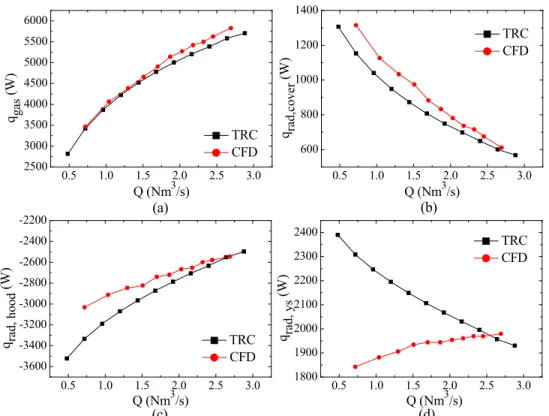
and from the thermal resistance circuit (TRC) model, as a function of the ventilation, for: (a) the exhaust gas (including Gadd’s experiments); (b) the top surface of the anode cover; (c) the surfaces of hoods and superstructure; and (d) the base of aluminum rod………..73 Figure 3.4 Comparison between heat transfer rates obtained from the CFD model and from the thermal resistance circuit (TRC) model, as a function of the ventilation, for: (a) heat content in exhaust gas; (b) radiation heat transfer from the top surface of the anode cover; (c) radiation heat transfer on the surfaces of hoods and superstructure; and (d) radiation heat transfer from the surfaces of yoke and stubs (y,s)………75 Figure 3.5 Average convection coefficients (solid symbols) and correlations (red
lines) with variable draft conditions, (a) on the top surface of anode cover, (b) on the surface of hoods and superstructure, (c) on the surface of rod, (d) on the surface of yoke and stubs………...77 Figure 3.6 (a) Local convection coefficient hcover (W/m2·K) on the top of anode cover
in normal draft condition; (b) local convection coefficient hys (W/m2·K) on
the surface of the anode assembly in normal draft condition……….80 Figure 3.7 Average forced and mixed convection coefficients with variable draft
conditions, (a) average convection coefficients on the top surface of anode cover, (b) average convection coefficients on the surface of hoods and superstructure, (c) average convection coefficients on the surface of rod, (d) average convection coefficients on the surface of yoke and stubs…...83 Figure 3.8 Inlet-to-outlet pressure drop (solid symbols) and correlation (red line)
versus draft condition……….85 Figure 4.1 Schematic view of the domain of the CFD model……….93 Figure 4.2 Heat losses due to convection and radiation from different components in
different ventilation conditions………...…99 Figure 4.3 Schematic of fins addition on anode assembly (case a2)…………...101
xv Figure 4.4 The difference of heat transfer rate extracted from bath by the top of the cell between normal condition and simulated scenarios………..101 Figure 4.5 Schematics of sealed hood gaps (case b1, left) and horizontal hood gaps
(case b2, right)……….….104 Figure 4.6 Schematic of more exposed stubs in the cavity (case c2)...106 Figure 5.1 (a) A plan of the studied smelter and (b) simulated domain representing a
slice of potroom………114 Figure 5.2 Positions where temperature measurements were performed…………..125 Figure 5.3 Air mass flow rate through different potroom openings under both normal
and reduced pot ventilations……….129 Figure 5.4 Air temperature profile in the middle plane of the sliced potroom under:
(a) normal and (b) 50% reduced pot ventilations……….131 Figure 5.5 Air temperature profile on a horizontal surface at height of 1.3 m above the
catwalk floor under: (a) normal and (b) 50% reduced pot ventilations…131 Figure 5.6 Temperature on hoods and superstructure under: (a) normal and (b) 50%
reduced pot ventilations………132 Figure 5.7 Mean radiant temperature on a horizontal surface at a height of 1.3 m
above the catwalk floor under (a) normal and (b) 50% reduced pot ventilations………...132 Figure 5.8 Comparison of the estimated DLE in 3 scenarios with normal pot
ventilation……….135 Figure 5.9 Difference of DLE between normal and 50% reduced pot ventilations, in 3 scenarios………...136 Figure 5.10 Vertical distribution of the DLE in scenario 1, under 50% reduced pot
ventilation……….137 Figure 6.1 Three CFD sub-models considered in this work: (a) potroom model; (b)
sliced pot model; (c) a 3D slice of potroom……….145 Figure 6.2 Schematic representation of the pressure difference distribution along the
xvi
Figure 6.3 Comparison of flow patterns between smoke tests and CFD results, (a) airflow in smoke tests; (b) airflow streamlines in the potroom model; (c) airflow streamlines in the sliced pot model………..156 Figure 6.4 Flow pathlines starting from the hood gaps under different scenarios: (a)
normal pot draft condition; (b) 50% reduced draft condition; (c) 50% reduced draft condition and one hood slid down……….158 Figure 6.5 Static pressure profile at a cross-section 0.85 m away from the central-plan
of the pot in the sliced pot model under different scenarios: (a) normal pot draft condition; (b) 50% reduced draft condition; (c) 50% reduced draft condition with the modification of coving of the lower half of hood gaps. ………..159 Figure 6.6 Estimated additional equivalent HF emissions in different scenarios of
hood placement under both normal and 50% reduced draft conditions… ………..162 Figure 6.7 Static pressure on the pot shell due to the air flow in potroom, (a) normal
draft condition; (b) 50% reduced draft condition………164 Figure 6.8 schematic representation illustrating the sealing of the lower half of hood
gaps………...166 Figure 6.9 Additional equivalent HF emissions from the pot when reducing the draft by half and sealing the lower half of the gaps between hoods, under different hood placement scenarios………..167
xvii NOMENCLATURE
A surface area, m2
Al abbreviation of aluminum
Af free area or total area of the holes, m2
Ap area of the plate (solid and holes), m2
a constant of the best fit for electrical resistivity, Ω·m b constant of the best fit for electrical resistivity, Ω·m/°C Cskin heat exchange on the skin by convection, W
Cd discharge coefficient through opening or hole Ce expansion coefficient through opening
Cp specific heat, J/kg·K
Cp_wind wind-induced pressure coefficient
Cres respiratory heat loss by convection, W
Dh hydraulic diameter of the opening on building wall, m
Dmax maximal water loss for human bodies, Wh/m2
Ebi emissive power of a blackbody from ith surface, W/m2
Eres respiratory heat loss by evaporation, W
Ereq required heat exchange by evaporation of sweat for thermal equilibrium, W
Fij view factor from surface i to surface j
Gr Grashof number g gravity, m/s2
H height, m
Href reference height in calculating wind speed profile from ground
Hmet height of the meteological tower, m
h gas sensible enthalpy, J/kg hconv convection coefficient, W/m2·K
conv
h average convection heat transfer coefficient, W/m2·K
hrad radiative coefficient, W/m2·K
I current in each rod, A
Ji radiosity from ith surface, W/m2
xviii
k turbulent kinetic energy,m2/s2
L length of a component in the direction of heat flux, m M metabolic heat generation, W
Mw molecular weight of the gas, kg/mol
m fin parameter in Eq. (2.17), m–1
m mass flow rate, kg/s
n second fin parameter in Eq. (2.17), K/m2
P perimeter of cross-section of a fin-like component, m p pressure, Pa
p’ “reduced pressure”, equal to pressure minus hydrostatic pressure, Pa pwind wind induced pressure, Pa
Qmax maximal heat storage, Wh/m2
q heat transfer rate, W
jh
q volumetric Joule heating, W/m3
q total heat flux, W/m2
rad
q radiative heat flux, W/m2
R universal gas constant, J/ K·mol
Rskin heat exchange on the skin by radiation, W
Re Reynolds number RSI R-factor, m2·K/W
Ri ith equivalent thermal resistance in the circuit (i=1-14) in Fig. 2.2b, K/W rj jth equivalent thermal resistance in the sub-circuit (j=1-6) in Fig. 2.3b, K/W
rreq evaporative efficiency at required sweat rate
Sh heat source term in energy equation, W/m3
Sreq required sweat rate, W
T temperature, K t plate thickness, m Tdp dew point of air, Cº Tsky sky temperature, K
xix Uref mean wind speed at an external reference position, m/s
ui, uj time averaged velocity components, m/s
W mechanical power and normally taken 0, x Cartesian coordinate, m
y+ dimensionless wall distance
Greek symbols
α, δ atmospheric boundary layer parameters and determined based on the classification of terrain category
fin system efficiency
θ temperature difference (TTgas), K
ρ density, kg/m3
ρe electrical resistivity, Ω·m
μ dynamic viscosity, Pa·s ε radiation emissivity εi ith surface emissivity
δij Kronecker delta
Subscripts
b base of a fin-like component, boundary condition cond conduction
conv convection
cover1 anode cover on crust layer cover2 anode cover on carbon anode d discharge
e expansion eff effective
gas gases in the cavity under hood i internal
xx
L tip of a fin-like component, boundary condition max maximum
mec mechanical ventilation met metology
nat natural ventilation o exterior of building op operation op operating pressure rad radiation ref reference req required
superhood superstructure and hoods in the pot t turbulence
xxi ACKNOWLEDGEMENTS
This thesis represents not only a summary of the results that I have achieved during the four-year Ph.D. program, it is also an evidence of a pleasant collaboration between an academic institute and an industrial enterprise, namely Université Laval and Alcoa. Without a close coordination between these partners, it would have been impossible to achieve the outcomes reported in this thesis. Based on this point, I will take this chance to express the deepest appreciation to the people who have made efforts in this project.
Professor Louis Gosselin has been a supervisor, colleague and friend, since I was recruited into his laboratory in 2010. His guidance has made this an amazing and rewarding journey. His patience and persistence have made a feeling that he always back up on me whenever I was in difficulties. His amity and generosity have helped me to be easily adapted to the new environment. During the four years, he spent much time to teach me, guide me and unselfishly convey his intelligence to me. Moreover, he also supported me not only academically and financially but also emotionally. Within his persistent helps, I have been able to work in a pleasant environment.
I would like to thank my co-supervisor, Professor Mario Fafard in Department of Civil Engineering and Water Engineering, who is also the director of the Aluminium Research Centre – REGAL and the NSERC/Alcoa chairholder. His involvement and coordination provided me some useful ideas and opportunities to attend in several international conferences. They enriched my knowledge and experiences and may encourage me pursuing higher level in this field. Special acknowledgements are given to the Alcoa’s staff, Donald P. Zeigler and Jayson Tessier. Donald, as my industrial advisor, helped me a lot by providing ideas and comments from industrial perspective during the course of my program. His guidance transferred me to think of questions in the perspective of industry and engineering. Jayson is a friendly person who devoted much time in my project. He always tried his best to help me performing experiments and inquiring the information I asked for.
I will also take this chance to appreciate all of my great colleagues in the laboratory. I would like to thank Guillaume Gauvin, who is responsible for my connection with the industrial partner. Abdellah Ousegui gave me a lot of academic comments in numerical simulations. All of my Ph.D. fellows, François Mathieu-Potvin,
xxii
François Grégoire, Benoît Allen and Maxime Tye-Gingras (research assistant), contribute their knowledge and experiences in my project. Thank you to other graduate and undergraduate colleagues in the laboratory and to my friends accompanying me during the four years.
This thesis has been funded by several organizations. The Chinese Scholarship Council (CSC) is the most appreciated sponsor. Without its four-year financial support, it is impossible to finish the thesis. The Fonds de recherche du Québec – Nature et technologie (FQRNT) provided a partially financial support in the thesis. A part of the research presented in this thesis was also financed by the intermediary of the Aluminium Research Centre – REGAL and the NSERC research chaire – Advanced Modelling of Electrolytic Cells and Energy Efficiency (MACE3). It is also grateful to Alcoa for its active involvement in the project.
I will finish the acknowledgements with a thank you to my family, which is also my fundamentally energy source for pursuing the Ph.D. degree. Thank you to my grandparents who taught me and cultivated me during my childhood. My parents, they are continuously supporting me in both finance and emotion to pursue high education level and are encouraging me to achieve more grand successes. My wife, Cen, came here to accompany me and made my life more comfortable. Thank you for your comprehension and contributions. Without the persistent supports from my family, I could not have been writing the thesis at this moment.
xxiii FOREWORD
Chapter 1 is an introduction to the background and current research progress of the subject studied in this work. Chapters 2 to 6 present scientific articles, each covering a sub-subject associated with the main topic. A comprehensive summary of the results is presented in Chapter 7, and also includes ideas for future work. The literature review of each article has been kept in each of their respective chapter. All the papers included in this thesis are listed below, and a brief statement of the role of each author in preparing each article follows, as requested by the FESP.
Chapter 2
Zhao, R., Gosselin, L., Fafard, M., Ziegler, D.P., Heat transfer in upper part of electrolytic cells: thermal circuit and sensitivity analysis, Applied Thermal Engineering, 54, 212-225 (2013).
Chapter 3
Zhao, R., Gosselin, L., Ousegui, A., Fafard, M., Ziegler D.P., Heat transfer and airflow analysis in upper part of electrolytic cells based on CFD, Numerical Heat Transfer, A: Application, 64(4), 317-338 (2013).
Chapter 4
Zhao, R., Gosselin, L., Fafard, M., Ziegler, D.P., Reduced ventilation of upper part of aluminum smelting pot: potential benefits, drawbacks, and design modifications, TMS-Light Metals, San Antonio, U.S., March 3-7 2013.
Chapter 5
Zhao, R., Gosselin, L., Fafard, M., Tessier, J., Airflow and thermal conditions in aluminum smelting potrooms under reduced pot ventilation conditions, Building Services Engineering Research and Technology, under review (2014).
Chapter 6
Zhao, R., Gosselin, L., Fafard, M., Tessier, J., Ziegler, D.P., Efficiency of pot tightness in reduced pot draft based on CFD simulations, International Journal of Heat and Fluid Flow, under review (2014).
For the paper in Chapter 2, my role was to propose the core idea of the paper and to develop the thermal circuit network for calculating the heat flux in the upper section of
xxiv
an aluminum smelting cell. I also developed a new expression for calculating the thermal resistance of a fin-like component with both convection and radiation with the environment. I wrote most of the paper. The second author (my supervisor) helped me to develop the model by presenting ideas and some derivations. He also contributed in the improvement of the writing and pictures. The third and fourth authors revised the paper and provided critical comments and suggestions from the industrial perspective.
For the paper in Chapter 3, I was involved in the development of the CFD model and the analysis of simulated results. I also proposed some ideas for the discussion based on the simulated results and wrote 80% of the text of the paper. The second author provided most important ideas in the analysis of the results and helped to edit the whole paper structure and to improve the writing. The third author guided me in both the general knowledge of CFD simulation and the detailed simulation procedure involved in the paper. The fourth and fifth authors were involved in the review of the paper and providing critical comments to improve it.
For the paper in chapter 4, I developed a CFD model to simulate the heat transfer in the upper part of aluminum smelting cell. In order to maintain the heat balance, I proposed and simulated several scenarios and designs of pot structure to estimate their efficiency on the enhancement of top heat loss. I was also in charge of the paper writing. The second author revised the paper and added 20% of text. The other authors were actively involved in the discussion and writing.
For the paper in Chapter 5, my role was to propose the topic and develop the required numerical model. I wrote 80% of the text and analyse the simulated results. The second author fully participated in the discussion and provided many critical questions. He also helped to improve the writing and added some new stuff. The third author performed the experiments for the validation of the numerical model, and provided an industrial point of view on the topic.
For the paper in Chapter 6, I suggested the main innovations of the paper and performed all numerical simulations. I also analysed the main results and wrote most of the paper. The second author revised the paper and added some ideas in the sections of validation and discussion. He also wrote 10% of the text. The other authors revised the paper and provided critical comments and suggestions from the industrial perspective.
xxv During my study in Université Laval, I also published other papers related to the aluminum industry. Due to the volume of the thesis, they were not included in this document, but they listed here:
Zhao, R., Nowicki, C., Gosselin, L., Duchesne, C., Energy and exergy inventory in aluminum smelter from a thermal integration point-of-view, manuscript in preparation.
Zhao, R., Gosselin, L., Fafard, M., Investigation of pot tightness and fugitive emissions based on CFD simulation, ICSOBA 2014, Zhengzhou, China, Oct. 12-14.
Zhao, R., Gosselin, L., Natural ventilation of a tall industrial building: investigation on the impact of modeling assumptions, eSim 2014, IBPSA-Canada’s biennial conference, Ottawa, May 7-10.
1 CHAPTER 1 INTRODUCTION
2
1.1 Introduction
Modern primary aluminum production is based on Hall-Héroult process. A schematic of a modern aluminum smelting cell is presented in Fig. 3.1a. The anode block is made from carbon and suspended in the electrolytic bath by an anode assembly. A carbon cathode is installed at the bottom of the pot cradle. Electrical current of high amperage circulates between the anode and the cathode through the electrolytic bath where alumina is periodically fed and dissolved. Electrochemical reactions that take place in the bath yield to the accumulation of a liquid aluminum layer on the cathode. The aluminum is siphoned out periodically. The carbon anode is consumed as deoxidizer, and CO2 is
continuously generated in the bath. Due to the effect of Joule heating, approximately half of the electrical energy is converted into heat. In a compact and very simplified way, the overall process is represented in the following way: 2Al2O3 + 3C + electricity 4Al +
3CO2. A layer of crust (a mixture of alumina and frozen electrolyte) is formed above the
bath and serves as a thermal insulator and gas scrubber.
Although the Hall-Héroult process is over a century old, the energy efficiency of modern cells is still relatively low, with roughly half of the electrical energy that leaves the cells in the form of waste heat (Grjotheim and Kvande 1986). Since primary production of aluminum is a process that requires extensive amounts of electricity (approximately 13-15 MWh/ton of aluminum produced), heat losses represent a large amount of energy. With an increasing demand in energy (especially in emerging countries) and a relatively slow development of alternative energy resources, the energy has becoming a global concern and energy saving is attracting increasing attention, not only in the aluminum industry but for the society in general. The primary aluminum production, as a traditional energy-intensive industry, should pay more attention on improving its energy efficiency. One promising solution lays in the utilization of large amount of waste heat dissipated from aluminum smelters.
The heat sources in an aluminum smelter can be summarized in three major processes. The anode baking process is required to convert the raw anode into green anode, in which combustion of released volatiles and natural gas is used to heat the carbon anode. The combusted gases are exhausted out of the baking furnace at approximately 150 °C which indicates a moderate heat content in the gases. The
3 aluminum casting process also dissipates heat. The liquid aluminum at 920°C is casted and eventually cooled to the ambient temperature. Compared with the two other processes, the aluminum electrolysis is the most energy-intensive process and approximately 50% of the electricity input is dissipated out of smelting pots. How to efficiently optimize the waste heat recovery from the pots should be addressed before an efficient usage of the heat be implemented. Moreover, the changes for the optimization will inevitably influence the pot working conditions in other aspects, such as the heat balance, pot tightness and so on. To predict and address these issues is also the prerequisite for an advanced waste heat collection from the pots.
1.2 Current progress
Good initiatives of waste heat recovery in aluminum industry require a comprehensive understanding of the production processes, especially for the aluminum electrolysis. This is because any strategy for waste heat recovery will inevitably influence current working conditions, positively or negatively. How to achieve a good trade-off between maximizing collection of waste heat and minimizing influences on the production is a crucial question. To address this question, researchers or engineers need a good knowledge of aluminum reduction cells. Many investigations have been aimed at gaining a better understanding of the electrolysis process and the heat transfer in reduction cells based on either analytical calculations or experimental measurements. In the following sub-sections, research progresses in aluminum reduction cells are introduced in different aspects that are strongly relevant to our initiative of waste heat recovery.
1.2.1 Mathematical models of the electrolytic cell
To better understand the heat and mass transfer in electrolytic cells, many simplified and convenient mathematical models of the electrolytic cell are established based on mass and energy balances. A dynamic model for the enthalpy balance of a specific aluminum electrolytic cell was built and the combined effect of all process kinetics can be observed over time (Taylor et al. 1996). Then the model was applied to analyse the generic energy imbalance in a modern industrial electrolytic cell and to guide a better control on the cell
4
performance. Another mathematical model of the electrolytic cell based on the heat balance was proposed in the PhD thesis of Biedler (Biedler 2003). This model was also used to predict the cell performance and guide the cell control. Yurkov and Mann (2005) proposed a simple dynamic real-time model for aluminum reduction cell control system. This model is simply solved and can provide sufficient adequacy to the real object. Jessen (2008) developed a comprehensive mathematical model of an electrolytic cell based on the previous models and this model can be used to predict the cell performance in various operating conditions and aid to maintain high productivity, energy efficiency and minimize the overall cost of operation. More recently, a new model considering the reactions in the cell space under hoods was developed in the literature (Gusberti et al. 2012) and the modeling of mass and energy balance is extend to the hooded cell space and provided a more comprehensive understanding of the electrolytic cell. These mathematical models are easily adjusted to a specific electrolytic cell and can provide relatively accurate predictions of the pot conditions.
Computational fluid dynamics (CFD) simulation has been employed to simulate the fluid flow and heat transfer in electrolytic cells in the last two decades. The electrolytic cell is discretized into small control volumes, and the governing equations that express the mass, momentum and energy balances can be solved in each volume via the finite volume method. Another set of equations that describes the electromagnetic field is solved and coupled with the flow movement in electrolytic cell to consider the interaction between the electromagnetic field and the electrolytic bath. The integrated simulation is known as the Magnetohydrodynamic (MHD) simulation of electrolytic cell. A 3D numerical model was developed by coupling the commercial codes ANSYS and CFX via in-house programs and customization subroutines (Severo et al. 2005). An electromagnetic model was built using Finite Element Method and the MHD flows of electrolytic cell were simulated in both steady-state and transient. The transient bath-metal interface was studied for cell stability. Doheim et al. (2007) considered the effects of gas bubbles and electromagnetic forces on the flow pattern and cell performance by using numerical simulations. A recent work reviewed the progress of the simulation methods on the flow and MHD instabilities in aluminum smelting cells in terms of their benefits, limitations and effectiveness (Zhang et al. 2010). Due to a huge volume of
5 relevant papers, only a few are mentioned here to indicate the importance of numerical simulations (CFD, MHD) in modeling aluminum reduction cells.
1.2.2 Top heat transfer in smelting cells
Although the abovementioned models involve the heat transfer from the top and sidewall of electrolytic cells, it is worth to summarize the literature that is specifically focused on the top or sidewall heat losses. Top heat loss refers to the heat transfer through a series of resistances from the electrolytic bath to the cavity under pot hoods. Heat is mostly generated in bath and transferred to the bottom of the crust by radiation and convection. Radiation heat transfer dominates in the process because of the extremely high temperature in the bath. A value of 100 W/m2K was employed to indicate the overall
heat transfer coefficient for the process with the bath temperature of 960°C in an 180kA cell simulation (Taylor et al. 1996). Taylor (2007) also proposed a thermal resistance model to describe the heat loss through the anode cover and anode assembly. The result indicated that the thermal resistance of the anode cover plays an important role in transferring the heat from the bath to the air in pot cavity. A stable crust layer with sufficient strength is necessary to maintain the integrity of the anode cover, and the cover with a proper thickness can prevent the anode from burning with the air. Tessier et al. (2008) found that the mixing and segregation of anode cover materials during cell operation can significantly change the anode cover composition, which leads to variations in the cover density and thermal resistance. The influence of particles size of anode cover materials on thermal conductivity was also reported in literature (Rye et al. 1995). The temperature dependence of the thermal conductivity of anode cover was investigated in cases with different particle size distributions in the work of (Shen 2006). More recently, Shen et al. (2008) performed measurements on the heat flux through anode cover in real plants. In the case of a loose alumina cover, the surface temperatures on anode cover varied from 160°C-300°C and the heat flux is correlated with the local cover temperature and is increased from 1500 W/m2 to 4000 W/m2. The surface temperatures of the crushed
bath cover were in the range between 170°C-260°C and the heat flux varied from 1500 W/m2 -3000 W/m2. The difference, the authors believed, was attributed to the different
6
material thermal conductivities in the two cases. The results indicated that the surface temperature and heat flux of the loose alumina cover are lower but have a stronger correlation between them than those of the loose crushed bath cover. Moreover, a correlation of the heat flux versus the cover thickness was also proposed in this work. A general tendency was found that the heat flux through anode cover is increased as the cover surface temperature increases (Eggen et al. 1992). The impact of moisture in alumina grains was studied in (Llavona 1988). The influence of the open holes in anode cover on the top heat loss was investigated in real plans in (Nagem et al. 2006; Gadd 2003). Cell fluoride emissions were increased with an increase of the collapsed anode cover, as reported in the literature (Nagem et al. 2005; Tarcy 2003; Dando and Tang 2006). It can be concluded that the thermal properties of anode cover has received much attention, and the variations in anode cover have a strong influence on the top heat losses.
Heat transfer through anode assembly was also investigated based on a simple 2D thermal resistance model in literature (Taylor et al. 2004). Relationship between anode cover thickness and the temperature of anode assembly is revealed by using this model. The results have illustrated that convective heat transfer dominates in normal condition while radiation should be considered in low draft condition because of extremely high surface temperature on anode assembly.
Heat loss in the pot cavity under hoods was studied in several papers. Experiments were performed to measure the exhaust gas temperature and the heat loss under different pot draft condition. For example, under normal condition, the heat loss from effluents can take up to 76% of the top heat loss in a 160 kA cell (Shen et al. 2008). In literature (Gadd 2003), a correlation of the exhaust gas temperature and the gas heat loss versus the draft condition was presented, and linear relation was found for both parameters but with opposite tendency. Nagem et al. (2006) used the exhaust gas temperature as an indicator to monitor the variation of the cell fluoride emissions in different operating conditions. Both of the two above papers also reported the variation of gas temperature in different hood openings and during anode changing. A comprehensive investigation on the top heat loss was found in most recent literature (Abbas et al. 2009), (Abbas 2010). The influence of various factors on the gas temperature and heat loss was
7 studied based on numerical simulations and some proposed modifications in pot structure aimed at enhancing the thermal quality of the exhaust heat.
More recently, waste heat recovery from the pot exhaust gas has received much attention. Sørhuus and Wedde (2009) developed a heat exchanger with a good trade-off between heat recovery and cost efficient cooling of pot gas. Promisingly stable heat exchange and minimum fouling deposits over longer test periods have been observed and encouraged manufacturer to continuously develop a commercial product. In 2010, they published their new tested results of a real heat exchanger in smelting cell plant (Sorhuus et al. 2010). A stable working of the heat exchanger provides heat directly to local heating system. The installation of this facility can not only further reduce the power consumption and total HF emission, but significant reduce the size of gas treatment center. Another work has reported to perform experiment to measure the potential heat recovery from pots, and a detailed analysis of fouling in heat exchanger was present (Fleer et al. 2010). Fanisalek et al. (2011) further studied a specific implementation of combining the waste heat recovery from pot exhaust gas with the water vaporization in desalination industry. Lorentsen et al. (2009) reported that Hydro in Norway has developed a new gas suction technology, which has a more efficient CO2 capture from
electrolytic cells, as well as reducing the total suction flow volume and fan power consumption.
1.2.3 Sidewalls heat transfer in smelting cells
Heat losses through sidewalls of smelting pots have received a lot of attention, in particular because it is very critical to maintain a frozen bath layer between the sidewalls and the liquid bath and metal, which is used to prevent the cell lining suffering from the aggressive environment in the bath (Grjotheim and Kvande 1986; Taylor 1984). A mathematic model was proposed to calculate a proper thickness of the frozen bath layer in smelting cells by solving a set of heat transfer equations (Haupin 1971). More recently, full 3D thermo-electric numerical models in high amperage cells were presented in the literature (Dupuis et al. 2004; Dupuis 2010). However, the values of heat transfer coefficients at the ledge surface are still not well determined. Severo and Gusberti (2009) have performed systematic and detailed numerical simulations to study the sensitivity of
8
the heat transfer coefficients between the ledge and the liquids (bath and metal) on different working conditions. Another numerical model, considering phase change in the cavity and bath regions, was presented in literature (Marois et al. 2009). A relatively simple mathematical model was presented to predict the variation of ledge thickness in the bath for different operating conditions in the literature (Kiss and Dassylva-Raymond 2008). A very high level of turbulence occurs in this region, which create a high heat transfer coefficient at the interface of bath and metal (Fraser et al. 1990). For example, 1000 W/m2K was adopted by Taylor to describe the heat transfer at the interface in
simulation work (Taylor et al. 1996). In conclusion, the mechanism of heat transfer at the interface of ledge and liquid (bath and metal) is still an open question (Solheim 2011). The heat transfer coefficient in the bath can vary significantly according to different operating conditions.
The overall heat transfer coefficient from the sidewalls to ambient was measured in the range of 18-20 W/m2K for a 165 kA aluminum reduction cell (Eick and Vogelsang
1999). In reference (Haugland et al. 2003), theoretical calculations were performed to calculate the free convection and radiation heat transfer coefficients separately. The results indicate that the convection coefficient is insensitive to the sidewall surface temperature, and on the other hand, the radiation coefficient is increased significantly with the increasing surface temperature. The overall coefficient is varied from 15 W/m2K to 30 W/m2K when the surface temperature is increased from 150°C to 350°C
with the ambient temperature of 20°C. Recently, researchers and engineers studied to achieve a better cooling on the sidewall by installing a series of heat exchanger modules (Namboothiri et al. 2009). The goal of this implementation is to add a more active sidewall cooling control which can remove more waste heat from the sidewall when a load creeping occurs in the pot. This application, called power modulation, is particularly beneficial for industries because it allows the pot to increase the productivity during night when the electricity price is usually lowest. However, there is still no systematic studies on the sidewall heat loss in the perspective of waste heat recovery.
9 1.2.4 Fluoride emissions from electrolytic cells
One of the environmental issues in the aluminum industry is the emissions of hazardous gases (mainly consisting of gaseous and particulate fluorides) produced in the electrolysis process as by-products. In modern electrolytic cells, a large volume of air is suctioned into the hooded pot space and dilutes the process gases. A collecting duct is installed above the pot superstructure and conducts the mixture of air and process gases into a gas treatment center. However, 100% hooding efficiency is barely guaranteed in real pot operation because pot hoods are periodically removed for operations, such as anode change, tapping of aluminum and so on. As a result, the vacuum in the hooded pot space is diminished and pot gases can escape from the upper openings on pot shell. Many efforts were devoted to enhancing pot tightness in such situations.
Fugitive emissions may occur in the pot superstructure all the time, even though the main source of emission comes from the gas leakage during pot operations. Since the control of hazardous gases is of great importance for the employees’ health in the potroom and for environmental reasons, an intensive research has been done to study the fugitive emissions of pots. The study of fugitive emissions was mainly based on experimental measurements and qualitative analysis. The early efforts were mainly devoted to monitoring the HF concentration in the pot off gas under different pot conditions and during various pot operations (Tarcy 2003; Slaugenhaupt et al. 2003; Dando and Tang 2005; Dando and Tang 2006). More recently, HF concentration was measured in the pot cavity to determine where HF is released from and to develop correlations between the various sources of water and the resulting HF emissions (Osen et al. 2011; Sommerseth et al. 2011). Although literature is abundant in this field, fewer works are available on the gas leakage into the potroom from the pot gaps. Dando and Tang (2005; 2006) reported the transient measurement of the HF concentration profile in the area just above pot hoods in different pot conditions. It was found that the thermal buoyancy from crust holes and the leakage of the pneumatic system of the alumina feeding system are the two main reasons explaining the HF release from pots when the hoods are into place. In addition to experiments, models were developed to calculate the pot draft and to investigate pot hooding efficiency (Dernedde 1990; Karlsen et al. 1998). These models consider the flow infiltration through pot gaps due to natural and
10
mechanical ventilations in the pot, but they are too simple to provide accurate results. The literature review indicates that there are few studies of fugitive emissions via numerical simulations, e.g., CFD simulations.
1.2.5 Heat and mass transport in potroom
In aluminum smelting plants, hundreds of electrolytic cells are lined up and hosted by a potroom with an extreme long length. Natural ventilation is normally employed in the potroom to remove the waste heat dissipated from cells. A proper design of the potroom is crucial to achieve an adequate cooling of the room space. Meanwhile, the potroom ventilation plays a role in diluting the hazardous gases in potroom, because current cells are not 100% tightness during the operation and an amount of fluoride materials is emitted into the potroom. To control the fluoride under certain regulatory limits is also an important parameter of potroom design. A relatively early study on the potroom ventilation was made by Dupuis (2001) where a 3D potroom model is developed in the CFX-4 commercial code and the turbulence can be properly simulated. A computational fluid dynamics (CFD) model was developed to aid the design of potooms in the Fjarðaál smelter (Berkoe et al. 2005). The flow in both the potrooms and the atmosphere surrounding the smelter is simulated and the design is verified based on the temperature and HF concentration. A more delicate CFD model was proposed to study the potroom ventilation by coupling with an innovative approach for the calculation of cell emission rates (Vershenya et al. 2011). The potroom design is also verified based on the air temperature and HF concentration in potroom. More recently, a new work consisting of building several CFD models of varying complexities is introduced to study the potroom ventilation in different working conditions (Menet et al. 2014). Another novel model, based on purely analytic calculation, provided a convenient tool to calculate the ventilation rate in potroom (Dernedde 2004).
1.3 Problematic and objectives
The literature review illustrated abundant research resources in the field of aluminum reduction cells. However, few papers were found to focus on the waste heat recovery
11 from cells. Although many analytical models were developed to describe the mass and heat transfer in electrolytic cells, there were few models that can perform a systematic analysis on the heat transfer from the standpoint of waste heat recovery. Since the working condition of electrolytic cells is very sensitive to the heat transfer from pot sidewalls, the focus of the present work will be on the top of the cell. It requires a simple but comprehensive method to model the heat transfer by conduction, convection and radiation. Meanwhile the model is capable of performing sensitivity analysis on some parameters of interest (e.g. the temperature and thermal content of pot exhaust gas).
By accounting for the different paths followed by the heat flux in the top of electrolytic cells, the pot exhaust gas is the most efficient access to the dissipated waste heat. Provided a reduction in the ventilated rate of the exhaust gas, thermal quality of the heat in the exhaust gas can be further enhanced. Recuperating heat from pots is not a new idea, as explained in the literature section. However, most of the findings are focused on collecting the flue heat in current working conditions, where the gas temperature is relatively low (~130˚C in summer and ~90˚C in winter) for advanced applications, such as power generation and heating a distant location. A few publications refereed to the reduction of pot draft condition in order to get higher flue temperature and concentration of CO2. However, a systematic analysis based on the practical viewpoint was not found in
literature.
In fact, there are at least three engineering problems that need to be addressed before a successful application of pot draft reduction. First, current heat balance should be maintained in the pot. A reduction of pot draft will sacrifice the capability of carrying away the top waste heat by the exhaust gas. More heat will be either accumulated in the bath or dissipated from the pot sidewalls. Neither of the ways is desirable for controlling the cell performance. Modifications should be done in the pot geometry or material properties to facilitate a better heat dissipation from the top of cell. Meanwhile it is expected that an additional portion of the heat will escape into the potroom, where the influence on temperature and flow pattern should be verified in a reduced pot draft condition. The last and most important aspect is how to deal with the fugitive emissions (i.e. hazardous materials, mostly consisting of gaseous and particulate fluoride, can leave from the hooded pot cavity into the potroom) under a reduced pot draft condition. A
12
reduction in gas suction inevitably creates a low vacuum in the hooded pot cavity, which can bring in a risk of emitting more gases into potroom.
Since the study of fugitive emissions is of great importance in the pot design, a design tool is required when doing any modifications. Experiments are a good choice but they are very expensive and time-consuming. In a conceptual design stage, it is impossible to build a prototype for real experiments. Moreover, the experiment can only provide the information on limited measured points. Numerical simulation has become a popular tool for the initial design in almost all industrial fields. A CFD model can provide a detailed flow tracking in and out of the pot and it is also easy to change the model geometry to represent different pot designs. Some of the publications presented the CFD simulation of hazardous gas transport in potroom (e.g. HF). Others mentioned in-house models to predict fugitive emissions. The CFD study of pot fugitive emissions in the coupling area (i.e. the modeling domain focused on the areas both in the hooded pot cavity and its surrounding potroom environment) is scarce and it requires a suitable model in this field.
Overall, the objectives of this thesis can be summarized as follows:
To develop a simple mathematical model for analyzing the heat recovery potential from the exhaust gases of electrolytic cells
To provide a systematical analysis of the feasibility of pot draft reduction, including the heat management in the cell and the potroom, the fluid flow in pot and potroom, and pot tightness for emission control
To develop a CFD model that can simulate the fugitive emissions from the hooded pot cavity to the potroom
To achieve a better understanding of the heat transfer and air flow patterns in pot and potroom.
1.4 Overview
In this section, a brief introduction is given for each of the following chapters. The introductions from chapter 3 to chapter 8 demonstrate the innovations or contributions of each article in this field.
13 In Chapter 2, an advanced thermal circuit model is developed to calculate the heat transfer in the top section of an aluminum reduction cell. One sub-network considers conduction and convection and the other one, radiation. They are coupled by substituting the calculated irradiation into the conduction equation as a source term. All major parts in the top section are considered and the parameters can easily be changed to perform a sensitivity analysis. A systematic analysis of the pot flue temperature and its heat content with respect to some pot parameters is performed and it is proved that the pot draft condition is the most influencing factor on the pot flue temperature. This conclusion led us to think about how to reduce the pot draft condition in order to increase the thermal quality of waste heat in the pot flue.
In Chapter 3, a CFD model is developed to study the heat transfer in the top section of an aluminum reduction cell. The simulated results are compared with those calculated from the thermal circuit model, and good agreement is obtained between them. By using the CFD model, the heat transfer coefficients on the main surfaces under the hooded pot cavity are studied and the results provide detailed information of heat transfer in the pot cavity. The relative importance of natural convection and forced convection in the pot cavity is revealed by analysis, for different draft rates. A good understanding of the heat transfer mechanisms in the top part of the cell is achieved.
In Chapter 4, the CFD model of top section of the cell is further developed to represent different modified pot designs. The purpose of the modifications is to maintain current top heat loss under a reduced pot draft condition, because the carried heat in the pot exhaust gas is also reduced with the draft reduction. A reduced pot draft can significantly increase the pot flue temperature, and at the same, save large amount of electricity for the ventilation system. It is found that the heat loss by radiation is also as important as that by convection in the hooded pot cavity, because the exposed yoke and stubs possess high surface temperatures and can emit a large amount of heat to the hoods and superstructure. The efficiencies of different scenarios are estimated and it is illustrated that the top heat loss can be enhanced to current level in 50% reduced pot draft. In Chapter 5, a 3D potroom sliced model is presented to study the air flow and heat transfer patterns in potroom. The model is used to assess the thermal comfort in the potroom under different pot draft conditions and outdoor conditions (wind and ambient
14
temperature). The influences of outdoor wind and pot-induced buoyancy force on the potroom ventilation are illustrated in the simulations. The results have indicated that reducing pot draft condition increases the heat stress very little in the potroom.
In Chapter 6, the pot tightness is investigated in a smelting cell with reduced draft, down to half of the current level. Several CFD models with different simulation length scales are created in order to iteratively define proper boundary conditions around the leaking area. A systematic analysis of the pot tightness is presented by considering various factors, e.g., pot draft, hood placement. The results have shown that current pot structure, even within ideal operating conditions, fails to maintain 100% hooding efficiency under a 50% reduced pot draft. Two design modifications are proposed and verified. An efficient sealing is observed when covering the lower half of the gaps between hoods.
15 CHAPTER 2 HEAT TRANSFER IN UPPER PART OF ELECTROLYTIC
16 Abstract
A model based on a thermal circuit representation was developed to study the heat transfer mechanisms in the top section of an aluminum smelting pot. In view of waste heat recovery applications, the sensitivity of the off-gas temperature and of the heat content in the gas with respect to several parameters was investigated. It was found that the draft condition was the most influential parameter. Additionally, the convection coefficients on the anode cover, and on the yoke and stubs proved to have a stronger influence on exhaust gas temperature, compared with the heat transfer coefficients on the hoods and rod. The results indicate that it is conceptually possible to increase both the gas temperature and the heat content, while maintaining at the same time the current operating conditions of the cell. Variations of the potroom temperature, hood insulation and anode height were also considered and affected significantly the gas temperature.
17 Résumé
Un modèle de type circuit thermique a été développé pour étudier les mécanismes de transfert thermique par le dessus de la cuve d’électrolyse. En vue de récupérer les rejets de chaleur, la sensibilité de la température des gaz d’échappement et de la quantité de chaleur qu’ils contiennent a été étudiée par rapport à plusieurs paramètres. Il a été trouvé que le taux de ventilation des cuves était le paramètre le plus influent. De plus, les coefficients de convection sur la couverture anodique, sur la barre transversale (yoke), sur les rondins ont aussi une grande influence sur la température des gaz, comparés aux coefficients de convection sur les capots et les tiges anodiques. Les résultats indiquent qu’il est conceptuellement possible d’augmenter à la fois la température et le contenu thermique, tout en maintenant en même temps les conditions d’opérations actuelles de la cuve. Les impacts de la température de la salle des cuves, de l’isolation des capots et de la dimension des anodes ont aussi été considérés et affectent significativement la température des gaz.
18
2.1 Introduction
Today’s dominant technology of aluminum production is based on the Hall-Héroult process. Electrical current circulates between a carbon anode and a cathode through an electrolytic bath in which alumina is dissolved. Thermo-chemical reactions that take place in the pot yield to the accumulation of an aluminum layer in the bottom of the cell which can be taken out of the cell periodically. The carbon anode is consumed during the process and consequently, CO2 is released. In a compact and very simplistic way, one can
write the overall process as: 2Al2O3 + 3C + electricity 4Al + 3CO2.
Although the Hall-Héroult process was patented in 1886, the energy efficiency of modern pots is still relatively low, with roughly half of the input energy leaving the pots in the form of waste heat. Since primary production of aluminum is a process that requires extensive amounts of electricity (approximately 13-15 MWh/ton of aluminum produced), heat losses represent large amounts of energy. Over the years, intensive research thus aimed at gaining a better understanding of how heat is lost through the different components of the pots (Grjotheim and Kvande 1986; Taylor et al. 1996; Rye et al. 1995).
Heat losses through sidewalls of smelting pots have received a lot of attention, in particular because they influence directly the thickness of the frozen electrolyte layer that forms on the internal surface of the refractory bricks and which is required to preserve the pot integrity (Grjotheim and Kvande 1986). Recently, sidewall heat exchangers have also been developed in view of controlling pot heat balance under power modulation and eventually using the recovered heat loss from sidewalls (Namboothiri et al. 2009).
Heat loss from the top of smelting pots (including the energy carried away by the effluents) is also important since it account for more than half of the total waste heat of smelting cells. Heat is transferred from the bath through the anodes and the anode cover (porous layer above the bath and anodes), and finally evacuated into the gas under hoods (Taylor et al. 2004). In the analysis of top heat losses, most attention has been devoted to the influence of the anode cover. Taylor (2007) proposed a simplified thermal circuit model describing the heat losses through the crust and anode cover. The result indicated that the thermal resistance of the anode cover plays an important role in transferring the heat from the bath to the air under hoods. Tessier et al. (2008) found that the mixing and
19 segregation of anode cover materials during cell operation can significantly change the uniformity of the anode cover composition, which leads to variations in the cover density and thermal resistance. This phenomenon has also been observed in (Hatem et al. 1988). The influence of particle size of anode cover materials on thermal conductivity was also reported in Rye’s research (Rye et al. 1995). More recently, Shen et al. (2008) performed measurements of the heat flux through different anode covers. The results indicated that the surface temperature and heat flux of the loose alumina cover are lower than those of the loose crushed bath cover. Moreover, a correlation of the heat flux versus the cover thickness was proposed in that work.
The studies regarding top heat loss associated with the effluents are scarcer in open literature. Gadd et al. (2000) had reported the measurements of the duct gas temperature and gas flow heat content in various process operations. Nagem et al. (2006) further studied the influence of the collapsed holes in the crust on the temperature of the effluent. Additionally, Taylor et al. (2004) created a simple 2D model to study the heat loss from the anode assembly, and demonstrated that convective heat transfer dominates radiative heat transfer under normal ventilation condition. Measurements have shown that the heat exhausted by the effluents represents 76% of the top heat loss (Shen et al. 2008). A simplified analytical model was presented by Karlsen et al. (1998) to estimate the cell tightness and gas collection efficiency in the cavity under hoods. One of the most comprehensive studies of top heat losses was presented by Abbas (2010). Based on CFD simulations and thermal circuits, different parameters of the pot were studied to find their influence on the top heat loss, and some geometrical modifications were proposed in view of waste heat recovery. In literature (Zhao et al. 2013), a detailed CFD analysis of the upper domain of the pot is proposed, in order to determine heat transfer coefficients on the main components under different ventilation rates.
As can be seen from the above review of open literature on the topic of heat loss from pot upper structure, the main focus so far has been on studying the physical and thermal properties of one specific component of the pot at a time. In the present paper, we propose a thermal circuit model describing the overall heat losses through the upper structure of a pot, from the free surface of bath to the ambient in potroom. Thermal circuits, thanks to their easiness to use and speed to solve, are thoroughly used to study

![Table 2.1 Correlations for average convection coefficients on four surfaces of the cavity, as a function of volumetric flow rate Q for one pot [Nm 3 /s] (Zhao et al](https://thumb-eu.123doks.com/thumbv2/123doknet/6666205.182577/50.918.121.795.200.404/table-correlations-average-convection-coefficients-surfaces-function-volumetric.webp)