HAL Id: hal-00802927
https://hal-mines-paristech.archives-ouvertes.fr/hal-00802927
Submitted on 20 Mar 2013
HAL is a multi-disciplinary open access archive for the deposit and dissemination of sci-entific research documents, whether they are pub-lished or not. The documents may come from teaching and research institutions in France or abroad, or from public or private research centers.
L’archive ouverte pluridisciplinaire HAL, est destinée au dépôt et à la diffusion de documents scientifiques de niveau recherche, publiés ou non, émanant des établissements d’enseignement et de recherche français ou étrangers, des laboratoires publics ou privés.
Bella Espinar, Didier Mayer
To cite this version:
Bella Espinar, Didier Mayer. The role of energy storage for mini-grid stabilization. 2011. �hal-00802927�
The Role of Energy Storage for
Mini-Grid Stabilization
Photovoltaic Power Systems Program
The role of energy storage for
mini-grid stabilization
IEA PVPS Task 11
Report IEA-PVPS T11-02:2011
July 2011
This technical report has been prepared under the supervision of PVPS Task 11 by: Bella Espinar and Didier Mayer,
Contents
Foreword 5
Executive Summary 7
1 Introduction 10
2 Scope of the study 14
3 The role of energy storage in mini-grid stabilization 15 4 Requirements for storage systems used for stabilization 17
4.1 Energy and power density . . . 17
4.2 Efficiency . . . 17 4.3 Discharge duration . . . 17 4.4 Lifetime discharge . . . 18 4.5 Reliability . . . 18 4.6 Response Time . . . 18 4.7 Ramp Rate . . . 18 4.8 Charge Rate . . . 19
4.9 Energy retention or “self discharge” time . . . 19
4.10 Emergency Power . . . 19
5 Storage technologies 20 5.1 Lead-acid batteries . . . 21
5.2 Nickel-cadmium batteries . . . 21
5.3 Lithium-ion batteries . . . 22
5.4 Sodium sulphur batteries . . . 23
5.5 Sodium-nickel-chloride batteries . . . 24
5.6 Redox-flow batteries: Va and ZnBr batteries . . . 25
5.6.1 Vanadium redox-flow batteries . . . 26
5.6.2 Zinc-bromine (ZnBr) redox-flow batteries . . . 27
5.7 Supercapacitors . . . 27
5.7.1 Case Study . . . 28
5.8 Flywheels . . . 31
5.8.1 Case Study . . . 32
6 Ability of different technologies to meet the requirements 33 6.1 Environmental impacts . . . 38
6.2 Cost . . . 39
7 Future research 43
List of Tables
1 Storage technologies characteristics (I). . . 35
2 Sources for Table 1. . . 35
3 Summary of energy storage technologies for small PV systems . . . 36
4 Storage technologies characteristics (II) . . . 37
5 Energy cost and power cost for energy storage technologies. . . 42
List of Figures
1 Measured and modelled PV system output on a day with frequent passing clouds . . . 112 Illustration of power fluctuation smoothing . . . 16
3 Storage classification with respect to function . . . 16
4 Energy capacity versus charging or discharging current for a Li-ion battery . 23 5 NaS battery . . . 24
6 Voltage regulation with NaS batteries . . . 25
7 Schematic of flow battery . . . 26
8 Structure of hybrid source . . . 29
9 Response of the system without supercapacitors to a positive load current step . . . 29
10 Response of the system with supercapacitors . . . 30
11 Flywheel system . . . 30
12 Principle of flywheel system . . . 30
13 Measured system response to a 350 kW step increase in load . . . 33
Foreword
The International Energy Agency (IEA), founded in November 1974, is an autonomous body within the framework of the Organization for Economic Cooperation and Develop-ment (OECD) which carries out a comprehensive program of energy co-operation among its member countries. The European Commission also participates in the work of the IEA.
The IEA Photovoltaic Power Systems Program (PVPS) is one of the collaborative R&D Agreements established within the IEA. Since 1993, the PVPS participants have been conducting a variety of joint projects in the application of photovoltaic conversion of so-lar energy into electricity. The mission of the IEA PVPS program is: to enhance the international collaboration efforts which accelerate the development and deployment of photovoltaic solar energy as a significant and sustainable renewable energy option. The IEA PVPS Program aims to realize the above mission by adopting four objectives related to reliable PV power system applications for the target groups of governments, electricity utilities, energy service providers and other public and private users.
1. To stimulate activities that will lead to a cost reduction of PV power systems appli-cations.
2. To increase the awareness of PV power systems’ potential and value and thereby provide advice to decision makers from government, utilities and international orga-nizations.
3. To foster the removal of technical and non-technical barriers of PV power systems for the emerging applications in OECD countries.
4. To enhance co-operation with non-OECD countries and address both technical and non-technical issues of PV applications in those countries.
The overall program is headed by an Executive Committee composed of one representa-tive from each participating country, while the management of individual research projects (Tasks) is the responsibility of Operating Agents. By mid 2010, thirteen Tasks were es-tablished within the PVPS program.
The overall goal of Task 11: “PV Hybrid Systems within Mini-grids" is to promote the role of PV technology as a technically relevant and competitive source in mini-grids. It aims at enhancing the knowledge-base of multi-source power generation systems including PV and associated electric distribution networks. The objectives of the Task are to:
• define concepts for sustainable PV hybrid mini-grids taking into account local factors (specificity of the application, financing regimes, location, others);
• provide recommendations on individual designs (mix of technologies, architecture, size, performances, other) in order to achieve high penetration level of PV as a mean to improve quality, reliability and economics of electrification systems such as mini-grids;
• assess the potential of technologies to be mixed with PV for hybridisation; and, • compile and disseminate best-practices on PV hybrid power systems.
The current members of the IEA PVPS Task 11 are: Australia, Austria, Canada, China, France, Germany, Italy, Japan, Malaysia, Spain, and United States of America.
This report gives an overview of how energy storage can provide mini-grid stability, that is, to match load power consumption with generated power within the mini-grid. The storage technology requirements are discussed. The technical report has been prepared under the supervision of PVPS Task 11 by:
Bella Espinar and Didier Mayer, Centre d’Energétique et Procédés (CEP), MINES Paris-Tech / ARMINES, Sophia Antipolis, France (FRA) with contributions by Ichiro Araki (JPN), Luis Arribas (ESP), Philippe Jacquin (FRA), Luiz Lopes (CAN), Konrad Mauch (CAN), Christoph Mayr (AUT) and Yann Tanguy (FRA).
The report expresses, as nearly as possible, the international consensus of opinion of the Task 11 experts on the subject dealt with. Further information on the activities and results of the Task can be found at: http://www.iea-pvps-task11.org and http://www.iea-pvps.org.
Executive Summary
Mini-grids may be designed to operate autonomously with or without connection to a central grid. While operating autonomously, they cannot rely on the central grid to provide stabilization to control the line voltage and frequency, balance supply and demand of power and manage real or reactive power.
Energy storage can provide stabilization in a mini-grid as follows: when the system works autonomously, storage provides or absorbs power to balance supply and demand, to counteract the moment to moment fluctuations in customer loads and unpredictable fluc-tuations in generation. When grid connected, energy storage systems also can provide ancillary services to improve power quality such as voltage and frequency regulation, harmonic filtering, and fault clearing (i.e. supply of short circuit current). This is named the power use of energy storage, contrary to the usual energy use of energy storage. Within Activity 24 of the IEA PVPS Task 11, stabilization of mini-grid systems in the power range up to 100 kW with a storage time operation up to two minutes was studied. Ideally, energy storage for mini-grid stabilization must have these features:
• High power density (more important than high energy density).
• High efficiency and little change of efficiency with the change of the rate of dis-charge.
• Discharge duration at its rated power (or higher if possible) for a minimum of two minutes
• High reliability.
• Very fast response time. • Flexible ramp rate. • Low cost.
The self-discharge characteristic of the storage system is not so critical when it is used for stabilization due to the frequent opportunities to recharge.
Nine storage technologies have been studied. Most of them are electrochemical bat-teries: Lead-acid, nickel-cadmium, lithium-ion, sodium-sulphur, sodium-nickel-chloride, vanadium redox and zinc-bromine. The remaining two technologies studied are electro-static energy storage by supercapacitors and mechanical energy storage by flywheels. Leacid is one of the oldest and most developed battery technologies. Its largest ad-vantages are the low cost compared to other storage systems and high reliability and efficiency. In contrast, its limited lifetime is its largest disadvantage.
Nickel-cadmium is also a very mature technology with high efficiency but a relatively low life cycle. Its most important disadvantage is that cadmium is a toxic element which poses issues associated with its disposal.
Lithium-ion has become the most important storage technology in the area of portable and mobile applications and electric vehicles. Also in stationary applications, it could be an interesting option because of its high flexibility. But the cost still remains very high. Sodium-sulphur has high efficiency, ramp up time within milliseconds and a pulse power capability over six times its continuous rating for 30 seconds. These attributes enables this technology to be economically used in combined power quality and peak shaving applications. The major drawback is that it needs to operate at a high temperature (over 350 centigrade degrees). Another drawback for mini-grids is that, even though the module unit power range is 50 kW, no complete systems less than 500 kW are available, because of present technological requirements.
Redox flow batteries have the advantage that the energy storage rating and power rating are decoupled. The size of the tank, where electrolytes are stored, determines the energy capacity of the battery and the charge / discharge surface area determines the power of the battery. There are several combinations of salts for redox flow batteries. In this report, zinc-bromine and the vanadium-vanadium combinations have been studied. The case of vanadium is a particularly interesting variant because vanadium can exist in four different valence levels, as a consequence of which vanadium can be used in both electrodes. However, the fact that it is necessary to pump the electrolytes to the reactor unit implies a relative low response time (in the order of seconds).
Double-layer capacitors (DLC) or supercapacitors are a new capacitor technology which fills the gap between classical capacitors used in electronics and general batteries be-cause of their nearly unlimited cycle-stability as well as extremely high power capability. Their advantages are durability, high reliability, no maintenance, long liftetime and quick charge / discharge characteristics with high current. Lifetime reaches one million cycles without any degradation but the solvent in the supercapacitor remains as a shortcoming, since it deteriorates in five or six years irrespective of the number of cycles. Finally, they are easily recycled or neutralized by environment-friendly means. Because of their prop-erties supercapacitors are suited especially for applications with a large number of short charge / discharge cycles, where their high performance can be used. This technology still exhibits a large development potential.
Flywheel energy storage systems store mechanical energy in a rotating cylinder. Mag-netically levitated bearings may be used to eliminate bearing wear and increase system life and the flywheel may be operated in a low density atmosphere, or vacuum, to reduce drag. Some of the key features of flywheels are low maintenance and long life (twenty years or tens of thousands of deep cycles). Flywheels are principally used in high power and short duration applications (e.g. hundreds of kilowatts in tens of seconds).
stabi-lization because of their response time and their power density: lead-acid, lithium-ion, supercapacitors and flywheels. Among them, only lead-acid is a very mature technology ready to implementation in mini-grids. However, for a pure mini-grid stabilization appli-cation, the battery bank may have to be oversized to meet the power demand - i.e. the energy storage capacity is larger than required. Commercial use of lithium ion batteries is currently limited primarily to low power applications, with the exception of some electric vehicle applications. High power lithium batteries for stationary use have an emerging commercial status, but the cost remains high. Flywheels and supercapacitors are suited to mini-grid stabilization because of long deep-cycle life and good response time but their cost is at present an important disadvantage compared to conventional batteries.
It must be kept in mind that these four technologies are considered the most suitable to deliver a specific short-term power for this mini-grid stabilization. The technology as-sessment may be different for applications in which both long-term energy storage and short-term power supply are required.
1
Introduction
Mini-grids can be defined as a set of electricity generators and, possibly, energy stor-age systems interconnected to a distribution network that supplies the entire electricity demand of a localized group of customers.
A key feature of mini-grids is that they can operate autonomously with no connection to a centralized grid. However a mini-grid may be designed to interconnect with the central grid and operate under normal conditions as part of the central grid with disconnection occurring only if required to maintain power quality (e.g. if there is a central grid failure). Alternatively, a mini-grid may be designed to operate autonomously in a remote location with the option to connect to the central grid when grid extension occurs [1].
Hybrid energy systems combine multiple energy generation or storage technologies to create an electricity generation system that optimizes the characteristics of the individual generation sources. PV hybrid systems usually combine photovoltaic (PV) generation of electricity with energy storage and a conventional fuel-based engine generator. These systems are often configured as mini-grids in which the generation sources supply loads through a relatively small local distribution grid. The use of this type of structure allows the minimization of losses in energy transport since the loads and generators are not very far apart [35]. Properly controlled energy storage devices provide energy for short term requirements to maintain or improve power stability on a mini-grid and also for long term requirements, such as shifting energy demand from on-peak hours to off-peak hours [15]. The grid characteristics of an autonomous system should be similar to those of an inter-connected system. The users of both autonomous and interinter-connected systems use the same kind of equipment and therefore require the same power quality to operate them [34]. Since mini-grids can operate autonomously, they cannot rely on the central grid to control line voltage and frequency and balance power supply with power consumption. Instead a mini-grid must manage its own real and reactive power flow and maintain its own control over voltage and frequency. Although many of the concepts and techniques employed to manage a large central grid are applicable, there are significant differences [1]:
• Since generators are commonly dispersed around the mini-grid, power flow is more complex than in the conventional centralized grid where power typically flows unidi-rectionally from large central generators to loads.
• Mini-grids often contain significant amounts of intermittent generation (e.g. PV or wind) whose power output can’t be controlled (dispatched) in the same fashion as conventional generators.
• Many mini-grid generators interface to the mini-grid with power electronic inverters whose control characteristics are different from the rotating synchronous machines used in conventional large generators.
Figure 1: Measured and modelled PV system output on a day with frequent passing clouds [56].
• It is usually not economically feasible to install the sophisticated supervisory control systems used in central grids nor to pay for network operators to manage the system on a continuous basis.
• There is often less load diversity in a mini-grid than in the much larger centralized grid, resulting in relatively larger and faster changes in load that must be accommo-dated by the mini-grid control.
Figure 1 illustrates the transient nature of PV generation as clouds pass over a typical residential system during the course of a day. Both the magnitude and the rate of the change in output are important: in mere seconds, the PV system can go from full output to essentially zero, and back again. At high levels of PV penetration, this intermittency can inflict troubles on load-side equipment, due to fluctuations, for example, in grid voltage. Equipment, both on the customer-side and the power-system-side, is designed to operate within a range of voltage, usually within ± 5 % of the nominal voltage. Lower voltages than the nominal one make many types of equipment perform poorly; light bulbs provide less illumination, induction motors can overheat and be damaged, and some electronic equipment will not operate at all. On the other hand, higher voltages than the nominal can damage equipment and shorten their lifetimes [32].
In a PV hybrid mini-grid, the non-predictable fluctuating nature of PV generation com-plicates the system management when PV penetration reaches sufficiently high levels. What is meant by “sufficiently high levels” depends, on the one hand, on the amount of available power reserves (also known as spinning reserve) to respond to sudden de-creases in PV output and, on the other hand, on availability of coordination mechanisms to manage PV output (e.g. a communication link among PV inverters) to reduce PV
gen-eration if load suddenly decreases. The former situation is also known as up regulation, and the latter, down regulation.
The spinning reserve in a PV hybrid mini-grid can be supplied by a rotating machine (i.e. a diesel genset), or by an energy storage system coupled to the mini-grid by a power converter. Provision of spinning reserve by a diesel genset has several limitations:
• In order to provide spinning reserve, the diesel generator must be operated at less than its rated capacity, but fuel efficiency is usually the highest when the generator operates near its rated capacity.
• The diesel generator responds to changes in PV generation or load initially by re-leasing or storing energy in the moving mass of the rotating elements (flywheel effect) and then by adjusting its fuel feed rate via its speed governor system. This response can result in transient deviations of mini-grid voltage and frequency that can last several seconds until the generator has reached a new steady-state oper-ating point. Large step changes in load or PV generation can cause the mini-grid frequency to go beyond the limits set in protective relays, causing nuisance tripping of the genset or other system components.
Energy storage systems with electronic power converters can be designed for fast re-sponse in up and down regulation with minimal transient voltage and frequency devia-tions. They can also support a diesel genset to perform up and down regulation with better transient response and better utilization of generator capacity.
Another problem to consider with intermittent diesel generator operation, where not all generator units are operating continuously, is that there can be relatively long time inter-vals (seconds to minutes) necessary to start and stop the units. For example, a system collapse can happen if the renewable power decreases faster than a diesel generator can start up to supply the load [34].
The fundamental requirement for mini-grid stability is to match load power consump-tion with generated power within the mini-grid. This requirement can be divided into the two response time categories: regulation and load following. Regulation responds to rapid load fluctuations (in the order of one minute) and load following responds to slower changes (in the order of five to thirty minutes) [26].
Grid-connected mini-grids
The primary motivations for implementing grid-connected mini-grids are to allow the inte-gration of high levels of distributed and renewable generation sources into the grid and to increase reliability and availability of electric power through the provision for autonomous operation. At this point grid-connected mini-grids are at the R&D stage with some demon-stration projects in progress.
When the mini-grid is connected to the central grid, there are other factors to take into account for supplying high quality electricity to consumers. The mini-grid must manage a smooth, transient-free transition between autonomous operation and interconnected operation in parallel with the central grid. The transition from interconnected operation to autonomous operation may be unplanned since it may be caused by a failure (black out or brown out) in the central grid. In that case the mini-grid will probably face an up-regulation or down-regulation situation since it will immediately cease importing or exporting power from, or to, the central grid. Energy storage systems installed in the mini-grid, with fast response and ability to both deliver and absorb power, provide a good means to handle this sudden mismatch between power generation and consumption and thus maintain mini-grid stability.
In addition, the mini-grid may have to supply ancillary grid services at the point of coupling to the central grid. These services may include:
• maintaining voltage regulation,
• meeting power quality standards (e.g.harmonics, flicker, etc.), • providing reactive power,
• and delivering short circuit current.
These requirements implicate for example the operation of fast energy storage systems because the decentralized generators in the mini-grid typically cannot deliver the neces-sary control dynamics. The connection of the storage system to the mini-grid is typically fulfilled via modern power electronic converters that can also provide the grid services [47].
2
Scope of the study
This report explores the role that energy storage can play in PV-hybrid mini-grids to match the fundamental requirement of stabilization in the sub-minute period: the balance be-tween generated power and power consumption at any time. The role of energy storage in supplying ancillary grid services in grid-connected mini-grids is not explicitly explored. However, in general, the requirements for energy storage systems suitable for mini-grid stabilization are similar to those suitable for providing ancillary services.
The available storage technologies for mini-grid stabilization will be analysed. The atten-tion will be focused in 100 kW power level storage systems since they are in the middle of the logarithmic scale of the range of mini-grid power ratings within the scope of Task 11. Most of the information available for mini-grid stabilization comes from simulations and few real case studies have been identified for this relatively small system power range. Thus, this report can serve as an overview of the storage possibilities for mini-grid stabi-lization, but this is not a guide of best practices due to the lack of information from real small power systems.
In addition, it must be kept in mind that, in the present study, the energy storage technolo-gies assessment is based on their power capabilities for mini-grid stabilization specific ap-plications. In systems where both long-term energy storage and short-term power supply are required, the assessment of the suitability of these energy storage technologies may be different.
3
The role of energy storage in mini-grid stabilization
Energy storage systems in PV hybrid mini-grids perform two roles [15, 40]:
• Short term power balancing (or bridging), related to the regulation of the mini-grid, in which the energy storage system absorbs or supplies power to maintain a balance between instantaneous power production and power consumption in the mini-grid. This ensures stability of voltage and frequency in the mini-grid. This can be classi-fied as a power application of the energy storage system in which the stored energy is discharged quickly (i.e., seconds to minutes) at high rates.
• Longer term energy management, related to the load following in the mini-grid, to match the time profile of non-dispatchable energy generators to the time profile of loads. For example, the energy storage system stores energy from the PV array during the day to deliver to loads at night. This can be classified as an energy application of the storage system in which the stored energy is discharged relatively slowly and over a long duration (i.e., tens of minutes to hours). Storage used for energy applications must have a much larger energy storage capacity than storage used for power applications.
Short term power balancing requires fast response (milliseconds), good, symmetrical (charge/discharge) power handling capability, good cycling life, and low cost per rated kWh of capacity, but generally requires only modest energy storage. Longer term energy management requires high energy storage capacity, good net efficiency, and low cost per kWh of capacity.
Storage provides up regulation by discharging (injecting energy into the grid), and it pro-vides down regulation by charging (energy is taken from the grid to be stored). Because of losses, only some of that energy can be discharged back into the grid when storage provides up regulation. So, efficiency is especially important for this application because there are so many up and down transactions. Figure 2 shows how short term output fluctuations can be greatly reduced by a storage unit.
Storage technologies that are best suited to energy applications include compressed air energy storage (CAES), pumped hydro storage (PHS), thermal energy storage (TES) and most battery types. Technologies best suited to power applicationss include certain types of batteries, flywheels, superconducting magnetic energy storage (SMES), electrochem-ical capacitors and super capacitors [19]. A new type of hybrid device, the lead-carbon asymmetric capacitor, is currently being developed and is showing promise as a device that might be able to serve both energy applications and power applications in one pack-age [56]. Figure 3 shows the storpack-age classification with respect to function.
SMES has been designed for energy applications as well as power applications. How-ever, it has only been actually manufactured as a product for power quality and distribution stability applications. This commercial power quality - SMES product, manufactured by
Figure 2: Illustration of power fluctuation smoothing [30].
Figure 3: Storage classification with respect to function. (Extract from [16]).
American Superconductor- is no longer being sold for energy purposes because other technologies have proved less expensive or easier to use. Instead it has evolved into a system called D-SMES that is being installed in multiple networked units for volt-amp reactive (VAR) control on distribution systems [49]. This technology is not considered further in the present study because it is not appropriate for the mini-grid power range of interest.
4
Requirements for storage systems used for stabilization
Ideally, energy storage for mini-grid stabilization must have these characteristics: high power density, high efficiency, discharge duration at its rated power (or higher if possi-ble) for a minimum of two minutes, high reliability, very fast response time, flexible ramp rate and minimum efficiency change with the rate of discharge. In this section all these characteristics will be explained.
4.1 Energy and power density
The power density (W/kg or W/l) is the rated output power divided by the volume of the storage device. The energy density is calculated as a stored energy divided by the volume. The volume of the storage device is the volume of the whole energy storage system including the energy storing element, accessories and supporting structures, and the inverter system [16]. These criteria are important in situations for which space is valuable or limited and / or if weight is important [19].
4.2 Efficiency
Storage system roundtrip efficiency is the amount of energy that comes out of storage relative to the amount put into the storage [19]. For storage that is used very frequently, to have an efficiency greater than 80 % becomes very important because of loss of energy in each cycle.
4.3 Discharge duration
Discharge duration is the amount of time that storage can discharge at its rated output power without recharging. Discharge duration is an important criterion affecting the tech-nical viability of a given storage system for a given application and the storage plant cost. Some types of storage systems can discharge at a relatively high rate for relatively short periods of time (often referred to as “emergency” rating) but efficiency is lower in these cases [19]. For example, a storage device can operate at a nominal 1 MW, for 3 hours at 80 % efficiency; the same plant can provide 1.5 MW for up to 10 minutes, at 65 % efficiency.
4.4 Lifetime discharge
To one extent or another, most energy storage media degrade with use (i.e., during each charge-discharge cycle). The rate of degradation depends on the storage technology, operating conditions and other variables. This is especially important for electrochemical batteries.
For some storage technologies - especially batteries - the extent to which the system is discharged also affects the storage media’s useful life. Discharging a small portion of stored energy is a shallow discharge and discharging most or all of the stored energy is a deep discharge. For these battery technologies, a shallow discharge is less damaging to the storage medium than a deep discharge.
Note that many battery manufacturers can produce storage media with extra service life (relative to the baseline product) to accommodate additional charge-discharge cycles and/or deeper discharges. Of course, there is always a corresponding incremental cost for the superior performance. To the extent that the storage medium degrades and must be replaced during the expected useful life of the storage system, the cost for that re-placement must be added to the variable operating cost of the storage system [19].
4.5 Reliability
Ideally, storage should respond at its maximum efficiency and nominal response time for any state of charge. Like power rating and discharge duration, storage system reliability requirements are circumstance-specific. Little guidance is possible. The project design engineer is responsible for designing a plant that provides enough power and is as reliable as necessary to serve the specific application [19].
4.6 Response Time
Storage response time is the amount of time required to go from no discharge to dis-charge at its rated output power. Generally, storage response times are rapid (see Table 4), in contrast to some types of generation that take many minutes to some hours before generating at full output, such as combustion turbines or those fueled by coal [19].
4.7 Ramp Rate
An important storage system characteristic for some applications is the ramp rate: the rate at which power output can change. Generally, storage ramp rates are rapid, on the
order of milliseconds to seconds to ramp from zero to maximum power, depending on the technology. Power devices with a slow response time tend also to have a slow ramp rate [19].
4.8 Charge Rate
Charge rate is the rate at which storage can be charged. If storage cannot recharge quickly enough, then it will not have enough energy to provide the necessary service. In most cases, storage charges at a rate that is similar to the rate at which it discharges. In some cases, storage may charge more rapidly or more slowly, depending on the capacity of the power conditioning equipment, and the condition and/or chemistry and/or physics of the energy storage medium [19].
4.9 Energy retention or “self discharge” time
Energy retention or “self-discharge” time is the amount of time that storage retains its charge. The concept of energy retention is important because of the tendency for some types of storage to dissipate energy while the storage is not in use. Electrochemical storage is more prone to self discharge. In that case, the self discharge is due to chemical reactions that occur while the energy is stored. Each type of chemistry is different, both in terms of the chemical reactions involved and the rate of self discharge. This characteristic tends to be less important for storage that is used frequently. For storage that is used infrequently (i.e., is in standby mode for a significant amount of time between uses), this criterion may be very important.
4.10 Emergency Power
In some circumstances, it may be helpful if storage can provide power beyond its nominal rated output during situations involving an urgent, short duration, and infrequent need for power beyond the normal output of the system.
5
Storage technologies
There are two criteria to categorize the various electric energy storages: function and form. In terms of the function, energy storage technologies can be categorized into those that are intended firstly for high power ratings with relatively small energy content, making them suitable for power quality and spinning reserve applications; and those designed for energy management (see section 3). As shown in Figure 3, pumped hydroelectric stor-age (PHS), compressed air energy storstor-age (CAES), large-scale batteries, flow batteries, fuel cells and thermal energy storage (TES) fall into the category of energy management, whereas capacitors/supercapacitors, superconducting magnetic energy storage (SMES), flywheels and some batteries are in the category of power quality and reliability. This simple classification hides the wide range of technical parameters of energy storage de-vices. For example, several flywheel manufacturers are developing flywheels with higher energy to power ratios [16].
Storage technologies for electricity can also be classified by the form of storage into the following [16]:
• Electrical energy storage: (i) Electrostatic energy storage (capacitors and superca-pacitors); (ii) Magnetic/current energy storage (SMES).
• Mechanical energy storage: (i) Kinetic energy storage (flywheels); (ii) Potential en-ergy storage (PHS and CAES).
• Chemical energy storage: Electrochemical energy storage (conventional batteries such as lead-acid, lithium ion and flow-cell batteries such as zinc bromine and va-nadium redox).
Within the frame of this report, only storage technologies available for systems up to 100 kW are be detailed. For grid stabilization, the storage operational time is in the order of two minutes, and the response and ramp times must be well under a second. Therefore, there are some storage technologies that are not described in this report, as they are not available for small PV hybrid systems or their response time make them not adequate for this purpose. However, storage technologies which have near term potential to meet the requirements for small PV systems are included.
The rechargeable/secondary battery, which stores electricity in the form of chemical en-ergy, is the most mature and most commonly used storage technology in PV hybrid mini-grid applications. A battery is composed of one or more electrochemical cells and each cell consists of a liquid, paste, or solid electrolyte together with a positive electrode and a negative electrode. During discharge, electrochemical reactions occur at the two elec-trodes generating a flow of electrons through an external circuit. The reactions are re-versible, allowing the battery to be recharged by applying an external voltage across the electrodes. They can respond very rapidly to load changes and accept co-generated and/or third-party power, thus enhancing the system stability. Batteries usually have very low self discharge losses and can have a high energy efficiency (60 % to 95 %). However,
most batteries contain toxic materials. Hence the ecological impact from uncontrolled dis-posal of batteries must always be considered [16].
5.1 Lead-acid batteries
Lead-acid (Pb-acid) batteries represent one of the oldest and most developed battery technologies. There are many existing installations which have been in operation for up to 20 years. Their biggest advantage is the low cost compared to other storage systems, while their limited lifetime is the biggest disadvantage. Lead-acid batteries are commonly used in PV hybrid mini-grids for both stabilization and energy management aplications. The typical discharge time is minutes to days or even weeks. The power range is from 10 kW to 100 MW or even higher and the response time is in the range of milliseconds. Due to the modularity of batteries, storage systems of nearly any storage capacity and power can be built [47].
Lead-acid batteries have a low cost (300 $/kWh to 600 $/kWh), and a high reliability and efficiency (70 % to 90 %). They are a popular storage choice for power quality, UPS1
and some spinning reserve applications. While commonly used for energy management applications in PV systems, the technology has limitations because of its short life cycle (500 to 2 000 cycles) and low energy density (30 Wh/kg to 50 Wh/kg) due to the inherent high density of lead. Lead-acid batteries also have an appropriate range of ambient tem-perature operation for PV hybrid mini-grids, but performance degrades at temtem-peratures below 0◦C and self-discharge accelerates at temperatures above 40◦C [16].
5.2 Nickel-cadmium batteries
Nickel-cadmium (NiCd) is a very successful battery technology from a technical point of view, since is the only battery technology that still features a good power capability in very cold climates, at temperatures in the range of -20◦C to -40◦C, where lead-acid batteries
show some difficulties in operation. Operation in stationary applications is economically attractive only if very long cycle lifetimes can be achieved. For this, cycle numbers in the range of 20 000 would be necessary, which have not been demonstrated so far, but which should not be considered as impossible either. The efficiency of NiCd batteries is about 70 % and the discharge time is similar to that of lead-acid batteries, minutes to days or even weeks. It is possible to get shorter discharge time than for lead-acid batteries. The power range is 10 kW to 100 MW or higher and the response time is in the range of milliseconds [47].
NiCd batteries have a high energy density (50 Wh/kg to 75 Wh/kg), a robust reliability and very low maintenance requirements, but relatively low life cycles (around 2 500 cycles -better than most lead-acid batteries). These advantages over lead-acid batteries make
them favoured for power tools, portable devices, emergency lighting, UPS, telecoms, and generator starting. The main drawback of NiCd batteries is the relatively high cost (around 1000 $/kWh) due to the expensive manufacturing process. Cadmium is a toxic heavy metal hence posing issues associated with the disposal of NiCd batteries. NiCd batteries also suffer from “memory effect”, where the batteries will only take full charge after a series of full discharges. Proper battery management procedures can help to mitigate this effect [16].
NiCd technology competes with nickel-metal-hydride (NiMH) technology which is replac-ing NiCd in many applications to solve the environmental concern with use of cadmium. Portable NiMH batteries were introduced in the 1990’s for the rapidly increasing mobile phone and laptop computer markets. Portable NiMH batteries have similar characteristics and cell design as portable NiCd batteries, but the specific energy is about 50% higher [24, 29]. However, NiMH technology generally has poorer power performance, higher self-discharge, greater sensitivity to overcharging, and higher cost than NiCd technology. Current applications for NiMH are principally for small mobile and portable devices. NiMH batteries are also used in electric vehicles, needing in that particular case, thermal man-agement. In stationary applications, NiMH batteries are currently not competitive with industrial NiCd batteries, or with lead-acid batteries [29].
5.3 Lithium-ion batteries
Lithium-ion (Li-ion) has become the most important storage technology in the area of portable and mobile applications (e.g. laptop, cell phone, electric bicycle, electric car) within a few years. In stationary applications also, it could be an interesting option be-cause of its high flexibility [47].
Although Li-ion batteries have over 50 % of the small portable devices market, there are still some challenges for making large-scale Li-ion batteries. The main hurdle is the high cost (> 600 $/kWh) due to special packaging and internal overcharge protection circuits. Several companies are working to reduce the manufacturing cost of Li-ion batteries to capture large energy markets [16].
Lithium-ion batteries generally have a very high efficiency, typically in the range of 95 %. Nearly any discharge time from seconds to weeks can be realized, which makes them a very flexible and universal storage technology. All power ranges up to 100 MW or higher are available and the response time is in the range of milliseconds [47]. Also, one advantage for this technology is the easy monitoring and control of the state of charge, via a function of the voltage [42].
Conventional Li-ion batteries offer the advantages of large capacity and long life. But internal resistance causes the battery temperature to increase while charging or dis-charging at a high current. Thus, the charge and discharge rates are limited. A grid sta-bilization power storage system must keep pace with the rapid fluctuations of wind or PV
Figure 4: Energy capacity versus charging or discharging current for a Li-ion battery [22]. power generation, and it is therefore desirable that high current charging and discharging be possible.
To improve power performance battery materials and design have been optimized to lower the internal resistance, and obtain a battery that permits 2 C charge and discharge (1 C means a current of charging or discharging the rated capacity within one hour). The Figure 4 shows that the capacity remains nearly constant for high charging or discharging current (here equal to 2 C).
To maintain its stability and lifespan, the lithium-ion battery must be controlled with a monitoring unit. In particular, to avoid over-charging and over-discharging, a voltage balance circuit is often installed to monitor the voltage of each individual cell and prevent voltage deviations between cells [22].
5.4 Sodium sulphur batteries
A sodium sulphur (NaS) battery, as shown in Figure 5, consists of liquid (molten) sulphur at the positive electrode and liquid (molten) sodium at the negative electrode as active materials separated by a solid beta alumina ceramic electrolyte. The electrolyte allows only the positive sodium ions to go through it and combines with sulphur to form sodium polysulphides. During discharge, positive sodium ions flow through the electrolyte and electrons flow in the external circuit of the cell producing around 2.0 V. This process is reversible, as charging causes sodium polysulphides to release the positive sodium ions back through the electrolyte to recombine as elemental sodium.
The battery is kept at 300◦C to 350◦C to keep the electrodes molten. NaS batteries have
a typical life cycle of around 2 500 cycles and typical discharge time is several minutes to days or weeks. Their typical energy and power density are in the range of 150 Wh/kg to 240 Wh/kg and 150 W/kg to 230 W/kg, respectively. NaS battery cells are efficient (75 % to 90 %) and have a pulse power capability over six times their continuous rating (for 30 s). This attribute enables NaS batteries to be economically used in combined power quality and peak shaving applications. The NaS battery technology has been demonstrated at over 30 sites in Japan for peak shaving and Germany, France and USA have also NaS
Figure 5: NaS battery [44]
batteries in operation. The main drawback is that a heat source is required which uses the battery’s own stored energy, partially reducing the battery performance, as the NaS battery needs to operate at a high temperature as mentioned above. For daily utilization, the temperature of the battery can be nearly maintained by its own reaction heat with appropriately dimensioned insulation. Initial capital cost is another issue (2 000 $/kW and 350 $/kWh approximately), but it is expected to fall in the future [16, 47].
These batteries are suitable for applications with daily cycling, but are inappropriate for applications in UPS with long service life and standby time. The power range is 50 kW to 100 MW. However the minimum module size is 50 kW, and it is not possible at the moment to use only one isolated module because of its thermal needs. Thus, the commercial power range is in the order of 1 MW [56]. Nevertheless, as the response time is in the range of milliseconds and NaS batteries meet the requirements for mini-grid stabilization, this technology could be very interesting for mini-grids if future research results in systems sized to the needs of PV mini-grids [44, 47].
As an applied example of this technology for mini-grid stabilization, Figure 6 demonstrates that the critical load voltage is well regulated thanks to the response of NaS battery [45].
5.5 Sodium-nickel-chloride batteries
The sodium-nickel-chloride (NaNiCl) battery, better known as the ZEBRA battery, has been developed by Zebra Technologies in Europe for transport applications, and is cur-rently being considered for some stationary applications, such as peak shaving, in the
Figure 6: Voltage regulation with NaS batteries [45].
USA [56]. It is a high temperature (around 300◦C) system that uses nickel-chloride as
its positive electrode and has the ability to operate in a broad temperature range (-40◦C
to +70◦C) without cooling. Compared to NaS batteries, NaNiCl batteries can withstand
limited overcharge and discharge and have potentially better safety characteristics and a high cell voltage (2.58 V). The disadvantages with respect to NaS batteries are their low energy density (around 120 Wh/kg) and power density (50 W/kg approximately), al-though the former still represents a considerable improvement over the Pb-acid battery technology. These batteries have been successfully implemented in several electric ve-hicle designs, and present interesting opportunities for fleet applications. The NaNiCl battery is mostly an “energy” battery and thus primarily suitable for battery-electric ve-hicles; its specific power being rather modest for hybrid applications [38]. At present research is developing a high power version of the ZEBRA battery for hybrid electric ve-hicles, a high energy version for storing renewable energy and a load-levelling battery for industrial applications [16].
5.6 Redox-flow batteries: Va and ZnBr batteries
In redox-flow batteries, the active material is constituted of a salt, which is dissolved in two different fluid electrolytes. The electrolytes are stored in tanks or reservoirs and are pumped, when needed, into a central reaction unit for the charge or discharge process. The size of the tank determines the energy capacity of the battery and the charge / discharge surface area determines the power of the battery (Figure 7). The advantage here is that the energy storage rating and power rating are decoupled. To gain additional
Figure 7: Schematic of flow battery [58]
storage capacity, it is only necessary to increase the volume of the associated storage tank [15]. Thus this battery technology is very well suited for large-scale applications because the construction of bigger tanks can be done very easily and effectively [47]. Flow batteries can release energy continuously at a high rate of discharge for up to 10 h [16].
Important combinations of salts, which are under investigation, are Fe/Cr, Br2/Cr,
Va-nadium and NaBr+Na2S4/Na2S2+NaBr3 (Regenesys). Researchers in Japan are also
working on uranium redox flow batteries.
5.6.1 Vanadium redox-flow batteries
Among redox-flow technologies, the vanadium redox-flow battery (Va redox) is a particu-larly interesting variant, because vanadium can exist in four different valence levels, as a consequence of which vanadium can be used in both electrodes. Vanadium batteries are currently commercially available on the market. Typical applications are enhanced power quality, uninterruptible power supplies, peak shaving, increased security of supply and integration with renewable energy systems. The efficiency of most systems is in the range of 60 % to 75 %. Typical discharge times are minutes to weeks. The power range is 10 kW to 100 MW or higher and the response time is in the range of seconds [47]. The suitability of this technology for grid stabilization is demonstrated in the State of Utah (USA) where a 250 kW, eight–hour discharge vanadium redox battery system is installed, to stabilize a long rural distribution line that was suffering voltage stability problems due to load growth [15].
5.6.2 Zinc-bromine (ZnBr) redox-flow batteries
The concept is very similar, but other materials are used. The ZnBr battery can be re-peatedly fully discharged without any damage to the battery and has a life of at least 1 500 charge / discharge cycles. This battery is ideally suited in applications that require deep cycle and long cycle life energy storage.
The ZnBr battery is predominately made with low cost, recyclable plastics and manu-factured with techniques suitable for mass production and at low production costs. The zinc-bromine energy storage system is now in the first stages of commercialization and there are already some stationary installations, including trial systems at Magnetic Island, Australia. The efficiency of zinc-bromine batteries is about 75 %. Typical discharge time is minutes to weeks. The power range is 10 kW to 100 MW or higher and the response time is in the range of seconds [47].
Some kilowatt-hour-units are now available pre-assembled, complete with plumbing and power electronics. Individual 50 kWh modules for renewable energy applications are also available [16].
5.7 Supercapacitors
Electrochemical double-layer-capacitors (DLC), also known as supercapacitors, are a new capacitor technology which fills the gaps between classical capacitors used in elec-tronics and general batteries, because of their nearly unlimited cycle-stability as well as extremely high power capability and their many orders of magnitude higher energy stor-age capability. This technology still exhibits a large development potential that could lead to much greater capacitance and energy density than conventional capacitors, thus en-abling compact designs [16, 23, 47].
Supercapacitors can be an auxiliary power source to complement the main energy source. They have a large specific energy and great specific power available over quite a long du-ration [13].
The two main features are the extremely high capacitance values, of the order of many thousands farads, and the possibility of very fast charges and discharges due to extraor-dinarily low inner resistance, which are features not available with conventional batteries [23].
Still other advantages are durability, high reliability, no maintenance, long lifetime and operation over a wide temperature range and in diverse environments (hot, cold, and moist). Lifetimes reaches one million cycles (or 10 years of operation) without any degra-dation but the solvent used in the capacitors remains as a shortcoming, since it
deterio-rates in 5 or 6 years irrespective of the number of the cycles [8]. They are environment-friendly, being easily recycled or neutralized [23, 36].
The efficiency is typically around 90 % and typical discharge times can be up to one hour for high energy devices. The power range is 10 kW to 100 MW and the response time is in the range of milliseconds [47]. They can reach a specific energy density of 4.5 Wh/kg and specific power density of about 3500 W/kg [36].
Because of their properties DLCs are suited especially for applications with a large num-ber of short charge/discharge cycles, where their high performance characteristics can be used. DLCs are not suited for the storage of energy over longer period of time, be-cause self discharge rate is high, their energy density is low and bebe-cause of their price [36, 47].
In an electric power system, most grid disturbances are very short (less than one sec-ond). Therefore, high power and low energy storage devices should be employed to compensate. These are the main features of the DLC. Its capability for quick charge and discharge can provide compensation repeatedly even if short-term voltage sags or mo-mentary interruptions occur again and again. A DLC system with a power electronic con-verter can control its output autonomously to suppress the quick fluctuation component of the grid voltage and thus it is well suited to power quality applications [15, 36, 54, 59]. Current applications for DLCs are, amongst others, hybrid electric vehicles and devices for voltage stabilization in power supply systems [13, 47]. The application in the electric power field in Japan has been tested mainly for voltage sag compensation and load fluc-tuation smoothing in a mini-grid system [54]. In the USA there are several supercapacitor energy storage systems installed in mini-grids to stabilize output from a wind turbine and a hydroelectric plant and to provide bridging power to the utility [15]. The application range of supercapacitors can be increased by combining them with other forms of en-ergy storage (e.g. batteries) to create hybrid enen-ergy storage systems that offer both high power capacity and good energy storage capacity [13].
Considerations in designing storage systems with DLCs are the low working voltage of a single capacitor cell (lower than 3 V) and that the terminal voltage drops to zero as the cell discharges. Thus the DLC can not act as a source of (approx.) constant voltage, like batteries, unless special technical measures are undertaken [23].
5.7.1 Case Study
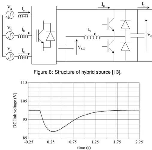
To illustrate the performance of DLCs in managing short term electrical fluctuations, we consider the system studied by [13] (Figure 8) which consists of a controlled rectifier supplied by a three-phase synchronous alternator and a DLC storage device connected to the DC link through a current reversible DC-DC converter. The generator is used as the main source of the system, and the storage device is used as the transient power
Figure 8: Structure of hybrid source [13].
Figure 9: Response of the system without supercapacitors to a positive load current step. (Extract from [13]).
source. The challenge was to regulate the DC link voltage, and to manage transient power demand, power peaks and regenerative breaking by controlling the two converters, taking into account alternator and supercapacitor constraints. The three phase sinusoidal current system (Ia, Ib, Ic) are in phase with the input three phase sinusoidal voltage
system (Va, Vb, Vc) in order to regulate the DC link voltage V0 to a reference level. VSC is
the supercapacitor voltage.
The Figure 9 presents, for reference, the voltage response of the system to a load step when it is not supplied by supercapacitors. Load perturbations have been created by generating squares waves on the load current with an amplitude of 10 A.
Figure 10 shows the transient response of the DC link voltage when the supercapacitor is present. Even though the system used by [13] is not a PV hybrid system, these graphics show the ability of supercapacitors for voltage regulation.
Figure 10: Response of the system with supercapacitors. (Extract from [13]).
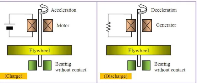
Figure 11: Flywheel system [2]
Figure 12: Principle of flywheel system (I. Araki courtesy)
5.8 Flywheels
Most modern flywheel energy storage systems consist of a massive rotating cylinder (comprised of a rim attached to a shaft) that is substantially supported on a stator by bearings (Figure 11). Storage energy is proportional to the square of rotational speed. To maintain efficiency, flywheel systems often use magnetically assisted or fully magnetically levitated bearings to reduce friction losses (and extend bearing lifetime) and are often operated in a low density gas (e.g. helium) or in a vacuum to reduce windage losses. The flywheel is connected to a motor/generator mounted onto the stator that, through some power electronics, interact with the grid (Figure 12). Some of the key features of flywheels are little maintenance, long life (20 years or tens of thousands of deep cycles) and environmentally inert material. Flywheels can fill the gap between short term ride-through and long term storage with excellent cyclic and load following characteristics [2, 16].
The efficiency of flywheels is typically higher than 80 %. The discharge time ranges from seconds to hours depending on the design of the flywheel. High power flywheels have a discharge time of some seconds and high energy flywheels in the range of minutes to hours. The power range is from 10 kW to 100 MW and the response time is in the range of milliseconds. Importantly, flywheel storage efficiency does not vary significantly as its output varies across a wide range of output levels [19].
The choice of using solid steel versus composite rims is based on the system cost, weight, size, and performance trades of using dense steel (200 m/s to 375 m/s tip speed) vs. a much lighter but stronger composite that can achieve much higher rim velocities (600 m/s to 1000 m/s tip speed). Actual delivered energy depends on the speed range of the flywheel as it cannot deliver its rated power at very low speeds [2]. The conventional metal rotor systems, with low speed metal rotor, lack the necessary energy storage capacity for long term applications and have relatively large standby losses. They are therefore typically used for short-term (between 10 s to 100 s) and medium / high load applications [16]. Composite flywheels are suitable for both high energy and high power applications. The current uses of flywheels are principally in high power/short duration applications (e.g. hundreds of kilowatts in tens of seconds). The most common application is as a power quality device to provide ride-through of interruptions up to fifteen seconds long or to bridge the shift from one power source to another. Such systems may be implemented in a hybrid configuration with stand-by generators (e.g. diesel generators). Flywheels have also been used for demand reduction and energy recovery in electrically powered mass transit systems (in the range of megawatts), for reactive power support, spinning reserve and voltage regulation [16]. Its application in renewable energy systems has not been very frequent, and the few existing examples can be found with wind turbines in rural electrification (wind-diesel systems) or for desalination in islands [11].
5.8.1 Case Study
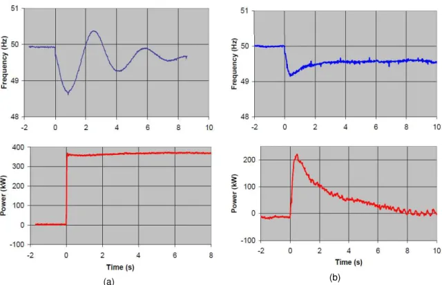
Figure 13 shows the reduced frequency fluctuation for a small grid in the Flores island of Azores (Portugal) [25]. The Flores power system has a mix of diesel, wind and hydro generation. The installed system consists of four hydro power generators (3× 250 kW + 1 × 600 kW), two wind turbines (2 × 315 kW) and four diesel generators (3 × 550 kW + 1 × 810 kW). Because of the type of control used on the hydro and diesel generators the renewable energy penetration on the Flores system was limited primarily by system stability; step response, spinning reserve and reactive power requirements were not lim-iting factors. A 350 kW/5 kWh flywheel energy storage system was added to the system with emphasis on improving frequency and voltage stability. The left column of the figure shows the measured system response (frequency and power), without the flywheel stor-age system, when a 350 kW step load was put on the system. The system frequency displays an underdamped oscillatory response with an oscillation frequency of approxi-mately 3 Hz, a minimum frequency of approxiapproxi-mately 48.6 Hz and a maximum frequency of 50.4 Hz. The right column of the figure shows the system response (frequency and power) after the installation of the flywheel energy storage. The system frequency is now well damped, with no oscillation apparent and settles to the new steady-state frequency in approximately four seconds. The minimum frequency is approximately 49.2 Hz. In conclusion, flywheels have rather good technical characteristics but cost and self-discharge are still a limitation for their use in small stand alone PV systems [46], but can be very useful in PV-Hybrid systems both for power quality issues in inverter domi-nated systems and for bridging power until a diesel generating set is started and ready to be brought on-line in genset dominated ones.
(a) (b)
Figure 13: Measured system response to a 350 kW step increase in load.
With no flywheel system (left column) and with flywheel system (right column) for fre-quency fluctuations. Blue line shows system frefre-quency; red line shows step load power.
6
Ability of different technologies to meet the requirements
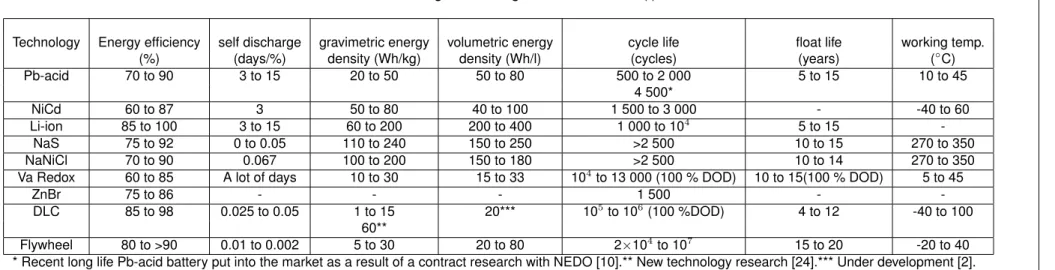
Tables 1, 3 and 4 provide a summary of energy storage technologies that can be inte-grated in PV hybrid mini-grid and grid-connected distributed PV generation. Any of these energy storage technologies may be appropriate for residential and small-commercial in-tegrated PV and storage systems in the near future [43, 56]. The self discharge unit is ’days/%’, meaning how many days are necessary to lose 1 % of charge.
For power fluctuation smoothing, the time step is in the range of some few seconds to some few minutes without expecting deep discharges.
From Table 1, because of the energy efficiency, the self discharge values, the energy density and life cycle, the technologies retained for the mini-grid stabilization application are Li-ion, NaS, NaNiCl, Va redox, DLC and flywheel, while Pb-acid batteries remain as an option because of their mature technology.
Because of the response time (Table 4), the Vanadium redox and ZnBr batteries are discarded as suitable technologies for this application, although they may be suited for energy storage. Their long response time in comparison to the other technologies is due to the need to pump the active materials to the reactor unit. Concerning the power range,
it is not possible to have a power range less than 1 MW for the NaS technology, despite the unit module size of 50 kW. Thus, NaS is not suitable neither. And from Table 3, it is noted that NiCd batteries have the problem of the toxicity of the cadmium. The NaNiCl battery will become affected by its nickel requirements once production reaches a few million units. The price of nickel has already tripled in recent years. This issue can be addressed, by replacing the nickel with iron. However, this potential sodium-iron-chloride variant has not yet been pursued actively [55]. Disposal issues also arise for Pb-acid batteries, and lead prices have also been very high in recent years.
After this analysis, the remaining technologies with good prospects for mini-grid stabiliza-tion applicastabiliza-tions are Pb-acid and Li-ion batteries, supercapacitors and flywheels.
Repor
tIEA-PVPS
T11-02:2011
Technology Energy efficiency self discharge gravimetric energy volumetric energy cycle life float life working temp.
(%) (days/%) density (Wh/kg) density (Wh/l) (cycles) (years) (◦C)
Pb-acid 70 to 90 3 to 15 20 to 50 50 to 80 500 to 2 000 5 to 15 10 to 45 4 500* NiCd 60 to 87 3 50 to 80 40 to 100 1 500 to 3 000 - -40 to 60 Li-ion 85 to 100 3 to 15 60 to 200 200 to 400 1 000 to 104 5 to 15 -NaS 75 to 92 0 to 0.05 110 to 240 150 to 250 >2 500 10 to 15 270 to 350 NaNiCl 70 to 90 0.067 100 to 200 150 to 180 >2 500 10 to 14 270 to 350
Va Redox 60 to 85 A lot of days 10 to 30 15 to 33 104
to 13 000 (100 % DOD) 10 to 15(100 % DOD) 5 to 45 ZnBr 75 to 86 - - - 1 500 - -DLC 85 to 98 0.025 to 0.05 1 to 15 20*** 105 to 106 (100 %DOD) 4 to 12 -40 to 100 60** Flywheel 80 to >90 0.01 to 0.002 5 to 30 20 to 80 2×10⁴to 107 15 to 20 -20 to 40
* Recent long life Pb-acid battery put into the market as a result of a contract research with NEDO [10].** New technology research [24].*** Under development [2].
Table 2:Sources for Table 1
Technology Energy efficiency self discharge gravimetric energy volumetric energy life cycle float life working temp. Pb-acid [10, 16, 24, 31][45, 47, 57] [16, 24, 52] [10, 16, 24][37, 52, 57] [16] [10, 16, 24, 52, 57] [24, 31] [24] NiCd [17, 24, 47] [24] [16, 37] [29] [3, 16, 24] - [3, 47] Li-ion [2, 10, 24, 31][42, 47, 57] [16, 24, 42, 52] [2, 3, 10, 16, 18][24, 37, 52, 57] [2, 16, 37] [24, 42, 52, 57][2, 9, 10, 16] - -NaS [10, 24, 31, 45, 47] [4, 16, 45] [10, 16] [16] [16] [16] [16, 47] NaNiCl [47] [16] [16] [16] [16] [16] [16, 47] Va Redox [2, 16, 28, 31][45, 47, 51] [16, 24, 40, 45] [16, 51] [16, 40, 45, 51] [16, 40, 50, 51] [31, 40] [40, 41] ZnBr [16, 47] - - - [47] - -DLC [16, 24, 57] [16] [5, 13, 16, 24, 36] [2, 16] [13, 21, 24] [5, 24, 36] [5, 27] Flywheel [12, 24, 31, 47] [16, 24] [16, 24] [16] [6, 16] [2, 16, 24] [12] 35
tIEA-PVPS
T11-02:2011
Technology Advantages Disadvantages Commercial Status R&D
Pb-acid Cost effectiveMature technology Low energy densityCycle life Globally commercial Reduce maintenanceExtend lifetime
NiCd
Energy density Cost Globally commercial Reducing cost
High power delivery Memory effect
Lifetime Environmentally hazardous materials
Abuse tolerant Low maintenance
Li-ion Energy densityHigh efficiency Cost Only globally commercial forvery small scale power range Safety system integrationReducing Cost
NaS
Energy density Cost Recently commercialized Reducing cost
No emissions Environmentally hazardous materials Reducing operating temperature
Lifetime High operating temperature Only available >500kW
Low maintenance NaNiCl
Energy density Internal resistance Globally commercial Reducing cost
Lifetime High operating temperature Reducing operating temperature
Cost
Va Redox
Lifetime Energy density Commercial production Reducing cost
Efficiency since 2007 Lifetime components
Low maintenance Standardization (pumps, cells)
Power and Energy are Performance
independently scalable ZnBr
Low maintenance Energy density Emerging global System integration
Power and Energy are Power density commercial status Lifetime components
independently scalable Standardization (pumps, cells)
DLC Long lifetimePower density CostEnergy density Emerging commercialstatus Energy densityReducing cost
Flywheel
Low maintenance Cost Emerging global Reducing cost
Lifetime Energy density commercial status Efficiency
Environmentally inert Reliability
Autodischarge rate Security issues
Table 4: Storage technologies characteristics (II)
Technology Power range Response time Source Pb-acid 0 to 100 MW milliseconds [16, 47] NiCd 10 kW to 100 MW milliseconds [47] Li-ion 0 kW to 100 MW milliseconds [47] NaS 50 kW to 100 MW milliseconds [45, 47] NaNiCl - - -Va Redox 10 kW to 100 MW seconds [31, 40, 47] and 500 kWh to 10 MWh ZnBr 10 kW to 100 MW seconds [47] DLC 10 kW to 500 kW milliseconds [13, 16, 47] Flywheel 10 kW to 100 MW milliseconds [6, 12, 47]
DLCs store electrical energy directly (via electrostatic storage) and they can be built in modular units. In comparison to batteries they show a poor energy density but they are able to deliver a large amount of power from a small volume during a short time. DLCs are ideal for high-power, short-duration applications because they are capable of deep discharge and have a virtually unlimited life cycle. Due to these advantages, a great deal of research is being focused on developing DLCs that can be used for small-scale stationary energy storage. One way of introducing DLCs for mini-grid applications is in combination with traditional batteries to gain the benefit of their complementary charac-teristics [30, 56]. Encouraging results have been obtained from experiences for frequency regulation with supercapacitors in Guadeloupe island (France) [59].
Nevertheless, the electrochemical technologies are still good candidates. Figure 14 il-lustrates several battery and capacitor technologies in relation to their respective power / energy capabilities. The lead-acid battery stands as the traditional benchmark. The plot shows that significantly greater energy and power densities can be achieved with several rechargeable lithium battery technologies.
To date, the advantages of Pb-acid technology, such as low cost and availability, have made it the default choice for energy storage in most PV applications. Indeed, new developments in valve-regulated lead-acid (VRLA) technology might revolutionize this well-established technology. Several manufacturers are developing a VRLA prototype batteries that promise to overcome the main disadvantages of Pb-acid batteries by using special carbon formulations in the negative electrode. The added carbon inhibits hard sul-fation, which minimizes or eliminates many common failure mechanisms (e.g., premature capacity loss and water loss). In cycling applications, this prototype could dramatically lower the traditional battery energy costs by increasing life cycle, efficiency, and reliability. At the moment, this prototype is primary aimed for electric vehicles [56].
Traditionally, NiCd batteries have been the replacement for Pb-acid; but, due to various operational and environmental issues, industry is moving away from this technology as newer and better technologies are developed, such as Li-ion.
![Figure 1: Measured and modelled PV system output on a day with frequent passing clouds [56].](https://thumb-eu.123doks.com/thumbv2/123doknet/8207160.275773/13.892.192.700.129.474/figure-measured-modelled-pv-output-frequent-passing-clouds.webp)
![Figure 2: Illustration of power fluctuation smoothing [30].](https://thumb-eu.123doks.com/thumbv2/123doknet/8207160.275773/18.892.232.668.132.420/figure-illustration-of-power-fluctuation-smoothing.webp)
![Figure 4: Energy capacity versus charging or discharging current for a Li-ion battery [22].](https://thumb-eu.123doks.com/thumbv2/123doknet/8207160.275773/25.892.261.628.136.305/figure-energy-capacity-versus-charging-discharging-current-battery.webp)
![Figure 5: NaS battery [44]](https://thumb-eu.123doks.com/thumbv2/123doknet/8207160.275773/26.892.228.671.134.499/figure-nas-battery.webp)
![Figure 6: Voltage regulation with NaS batteries [45].](https://thumb-eu.123doks.com/thumbv2/123doknet/8207160.275773/27.892.259.634.130.533/figure-voltage-regulation-with-nas-batteries.webp)
![Figure 7: Schematic of flow battery [58]](https://thumb-eu.123doks.com/thumbv2/123doknet/8207160.275773/28.892.192.700.131.423/figure-schematic-of-flow-battery.webp)