HAL Id: hal-00869514
https://hal.archives-ouvertes.fr/hal-00869514
Submitted on 3 Oct 2013
HAL is a multi-disciplinary open access
archive for the deposit and dissemination of
sci-entific research documents, whether they are
pub-lished or not. The documents may come from
teaching and research institutions in France or
abroad, or from public or private research centers.
L’archive ouverte pluridisciplinaire HAL, est
destinée au dépôt et à la diffusion de documents
scientifiques de niveau recherche, publiés ou non,
émanant des établissements d’enseignement et de
recherche français ou étrangers, des laboratoires
publics ou privés.
two-sensing-finger microgripper.
Bilal Komati, Kanty Rabenorosoa, Cédric Clévy, Philippe Lutz
To cite this version:
Bilal Komati, Kanty Rabenorosoa, Cédric Clévy, Philippe Lutz. Automated guiding task of a flexible
micropart using a two-sensing-finger microgripper.. IEEE Transactions on Automation Science and
Engineering, Institute of Electrical and Electronics Engineers, 2013, 3, pp.515-524. �hal-00869514�
Automated Guiding Task of a Flexible Micropart
Using a Two-Sensing-Finger Microgripper
Bilal Komati, Kanty Rabenorosoa, C´edric Cl´evy, and Philippe Lutz, Member, IEEE
Abstract—This paper studies automated tasks based on hybrid force/position control of a flexible object at the microscale. A guiding task of a flexible micropart is the case of the study and is achieved by a two-sensing-finger microgripper. An experimental model of the behavior of the microgripper is given and the interaction forces are studied. Based on grasp stability, a guiding strategy taking into account the pull off forces is proposed. A specific control strategy using an external hybrid force/position control and taking into account microscale specificities is proposed. The experimental results of automated guiding task are presented.
Note to Practitioners— This article’s motivation is the need of very precise positioning in micromanipulation and microassembly tasks. The guiding tasks are a part of the microassembly process. Such guiding tasks are rarely automated. This is mainly due to the fact that automation in the microworld is a new issue and the literature only concerns the local control of microactuators and microrobots for the moment. Hybrid force/position control is a promising approach to achieve an automated guiding task of the micropart. To detect the contact between the micropart and the rail, a two-sensing-finger microgripper is used. The controller aims to release the contact and to continue going forward within the guiding axis. The proposed controller is very accurate, with high speed (low rejection time) and easy to implement. It is noticed that the proposed control scheme can also be applied to other microassembly tasks (pick-and-place, insertion, etc).
Index Terms—Microassembly, hybrid force/position control, automated task, flexible micropart, compliant micropart, two-sensing-finger, microgripper, gripping force, lateral contact, mi-crorobot control, mimi-crorobotics.
I. INTRODUCTION
Nowadays, miniaturized systems which integrate intelli-gence and functionalities are more and more required. These systems are either micromechanisms (micro ball bearings, microgears, micromotors), micro-optical systems (switches, lasers) or hybrid Micro-Opto-Electro-Mechanical Systems (MOEMS) like microscanners, microspectrometers [1], [2], [3]. The integration of MEMS (Micro-Electro-Mechanical Systems) and MOEMS (Micro-Opto-Electro-Mechanical Sys-tems) technology in commercial products is growing especially in the field of telecommunication and sensor technologies [4]. The microfabrication limitations have helped the growth of the microassembly field. The main purpose of microassembly
The authors are with FEMTO-ST Institute, UMR CNRS 6174 - UFC / ENSMM / UTBM, Automatic Control and Micro-Mechatronic Systems Department, 25000 Besancon, France, (e-mail: bilal.Komati@femto-st.fr, kanty.rabenorosoa@femto-st.fr, cclevy@femto-st.fr, philippe.lutz@femto-st.fr.)
is to assemble microparts produced from various fabrication processes into one complex product. The use of robotic work-stations equipped with micropositioning stages, a microgripper and vision systems is commonly practiced at the microscale.
Automated robotic microassembly is the final objective which is usually carried out by precise positioning [5], [6], [7] but it is not sufficient for all microassembly tasks [8]. Dual finger microgrippers with feedback are used to automate some microassembly tasks [6], [9]. The feedback could be vision, position or force feedback.
Most of the work deals with vision-based control [6], [10], [11]. It mainly enables position control and rarely takes into account the interaction forces like gripping forces and contact force between the grasped micropart and the substrate. Especially at the microscale, interaction forces have to be taken into account due to the predominance of adhesive forces. It is notably manifested by pull-off force which can be 84 times the 100µm x 1000µm x 1000µm silicon micropart weight [12]. Another important reason to take the forces into consideration is the fragility of the components (grippers, parts, etc). Indeed, the microgrippers may also easily be broken if the gripping forces are not taken into consideration. In addition, the integration of micropositioning sensors in the microassembly station is hampered by the size of sensors [8], [13].
In order to achieve automated microassembly and to avoid the destruction of microparts, a control of the gripping force is often used [14], [15], [16]. The detection of contact and the control of the impact force are performed in [17], [18]. There are some tasks which are carried out by using force control like insertion [19], [8] and pushing [20]. In these works, AFM probes are often used or grippers with one sensing fingers and one actuated finger. The use of two-sensing-finger allows to detect the side of contact [21] and to control the gripping forces at the same time or independently (picking of a micropart). Such a system brings suitable information about the contact, provides more dexterity of the grasp and ensures more safety to not break microparts. In addition, the use of two-sensing-finger microgripper simplifies the pick of the micropart because the contact from the two sides will be easily detected.
In our previous work [22], we designed RFS-MOB (Re-configurable Free Space Micro-Optical Benches) that are based on generic components (holders and substrates). This principle can be easily used to design various MOEMS (µ spectrometer, coupling system, µ-confocal microscope, etc) and test benches (characterization of micro-optical devices). These holders include flexible structures (springs). However,
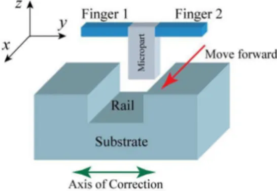
flexible microparts are of great interest for microassembly [23]. To automatically assemble microproducts such as RFS-MOB and achieve fine positioning, it is required to pick the holder to be assembled, to guide it along a rail and to release it. This guiding task is studied in this paper. In a previous paper [24], the guiding task of a rigid micropart was studied. In this paper, the guiding task of a flexible micropart in rail will be studied (see Fig. 1).
Fig. 1. Principle of a guiding task with move forward along X and correction along Y (use of a microgripper and a robotic workstation to control the trajectory of the handled micropart).
In our case, the automated guiding task (see Fig. 1) requires the control of both the gripping force applied by finger 1 and 2 on the micropart and the contact force between the micropart and the rail. For the considered micropart scale, interaction forces (gripping force, contact force, pull-off force) have to be taken into account and few tens of µN forces have to be controlled.
The objective of this paper is to study automated guiding tasks at the microscale and to investigate a suitable control scheme. Therefore, the integration of force sensors and axis of correction in the microassembly station is discussed and an experimental setup is proposed to achieve automated guiding tasks (Section II). The stability of the grasp, the two-sensing-finger microgripper modeling and the guiding strategy are investigated in section III. Section IV presents the proposed control scheme based on hybrid force/position control with an observer to estimate the contact force. Section V presents the experimental results of automated guiding tasks. Finally, section VI concludes this paper.
II. GUIDING SYSTEM CONFIGURATION
A. Integration of force sensors in the microassembly station
The development of force sensors for the microscale has been investigated by many researchers [25], [26], [27], [28] especially for micromanipulation and/or microassembly. Their integration in microrobotic systems is a very interesting ap-proach because it provides the information about the contact when it happens and it prevents from breaking components (gripper, microparts, etc). During microassembly, there are some interaction forces: (i) between a microgripper and a grasped micropart, (ii) between a manipulator and its environ-ment (for example the substrate), and (iii) between a grasped
micropart and its environment. The force sensors and the axis of correction can be configured in four ways:
(a) the manipulator is equipped with force sensors and the axis of correction is mounted on the workplace (location where are placed parts to assemble),
(b) the manipulator is equipped with force sensors and correcting axis,
(c) force sensors are mounted on the workplace and the axis of correction is on the manipulator,
(d) force sensors and correcting axis are on the workplace. The choice of the configuration depends on the task con-straints, technological capabilities and cost minimization. The study of hybrid force/position controlled tasks usually leads to define directions with unconstrained motion and directions with constrained motion [29], [30]. Force control is applied on the directions with constrained motion. In our case (guiding task along X), lateral contact may happen between the grasped micropart and the rail thus motions along Y and Z are force constrained contrary to the move forward motion along X (see Fig. 1). If we consider that the depth of the rail is enough to ensure no mechanical contact between the micropart and the rail, the motion along Z becomes unconstrained. The chosen configuration has to enable the measurement of the lateral contact force for ensuring its control during the task. To measure both gripping forces and the lateral contact force with minimum number of force sensors, configurations (a) and (b) can be chosen. The axis of correction generates a relative displacement between the grasped micropart and the substrate so there is no difference between (a) and (b), in terms of control. For this study, we will use a two-sensing-finger microgripper to achieve automated guiding tasks so we choose configuration (a) that provides a better sepsfness of the robot structure and a better stability for handling the micropart since in this case the soft micropart can be held by the microgripper with a constant clamping force.
B. Experimental setup
In this section, the experimental setup is proposed to per-form guiding tasks (see Fig. 2). It is based on two force sensors FT-S270 from FemtoTools with a measuring range of 2000µN and a resolution of 0.4µN. Each force sensor comprises a probe, of 3mm of length and 50µm of thickness, that moves along its main direction (Y according to Fig. 2) once a force is applied at its tip. The displacement is converted into a voltage thanks to a capacitive variation measured by a dedicated circuit. They work like a jaw of the microgripper and are mounted on x1y1z1 linear stages for Finger 1 and
x2y2z2 for Finger 2. The position control of fingers along
Y enables to open/close the resulting microgripper and apply the necessary force to pick the micropart. The manipulated micropart is 50 x 50 x 2000µm3
in size. The rail is mounted on a microrobotic structure (workplace) composed of xsyszs
coarse positioning, yplarge range but fine positioning, xnynzn
fine positioning, and θ rotation. The large range positioning stage is a P625.1CD from Physik Instrumente with 500µm of travel range and 1.4nm in resolution. The fine positioning stage is a P-611.3 NanoCube with 100µm range and 1 nm
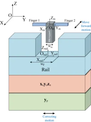
Fig. 2. Experimental setup proposed for achieving guiding tasks: a micropart is hold by two-sensing-finger microgripper. xnynznand ypenable guiding
motions of this micropart into a rail.
in resolution. A rotation stage is a SmarAct SR-3610-S with 1.1 µo in resolution is used to adjust the alignment between
the rails and the axis of the Nanocube. These three devices are sensorized and closed loop controlled. The rail width is adjustable from 0µm to 1mm enabling set up of the axial play between the grasped micropart and the rail.
Considering the pick of the micropart, initial gripping forces are applied by each finger onto the micropart. They are named preload and notedFy10, Fy20 (Subscripts 1 & 2 refer to finger
1 and 2 respectively. Subscript 0 refers to the constant preload applied, once the micropart is grasped). The displacement along X enables to position the micropart to the desired position into the rail. When the contact between the rail and the micropart appears, the rail position along Y has to be modified to cancel or reduce the force generated by the contact in order to preserve the stability and the reference frame of the micropart. This force is named thereafter lateral contact force. It has three components: Fx, Fy, Fz and we considerFx and
Fz smaller than Fy because they are the friction components
of the lateral contact force.
In the following, the microgripper remains fixed with the grasped micropart and the center of the microgripper is defined by a coordinate frame OmXmYmZm. The guiding task is
performed by actuating xn to move forward and by moving
yn for correcting when the contact happens (see Fig. 3). yp is
used during the validation for creating a known perturbation to test the control strategy proposed. OrailXrailYrailZrail is
the coordinate frame of the rail.wr is the rail width andwm
is the micropart width (wm ≤wr).
III. GUIDING STRATEGY FOR STABLE GRASP
Given the objective of the paper to achieve an automated guiding task, a guiding strategy is proposed in this section. For this purpose, the pull-off forces effect is investigated, the effect of perturbations along X, Y and Z are detailed, the model of the two-sensing-finger microgripper and the evolution of the gripping forces in presence of lateral contact force are investigated. This model will then be used to achieve automated guiding tasks in Section V.
Fig. 3. Guiding task based on two-sensing-finger microgripper with coordi-nate frames: OrailXrailYrailZrailand OmXmYmZm
A. Pull-off forces
During a microassembly process, contacts between sur-faces often happen. Surface force being predominant at the microscale, it is required to evaluate the influence of sur-face forces during a microassembly process. To automatically achieve guiding tasks at the microscale, pull-off force, which is the necessary force to break a contact due to sticking effect, has predominant role notably when a contact between the micropart and the rails happens.
It was shown in [12] that the pull-off force can reach 196µN for a planar 50µm x 50µm silicon surface size of contact that can typically happen in the present case. During the guiding task, the breaking of the lateral contact may induce a pull-off force for each side of the contact. In this case, the evolution of the lateral contact force according to the position of the micropart can follow curves in Fig. 4, i.e once a contact (micropart/rail) happens, the pull-off force acts as a sticking effect. In Fig. 4, the micropart is supposed to be at pointOM.
While moving the micropart, it could approach from a sidewall until a contact happens at point A or C and the lateral contact force increases as the object still move in the same direction along Y. To break the contact, the micropart should be moved in the opposite direction until the point A or C. At points A and C, the lateral contact forces are zero but the contact remains due to adhesive force. The contacts are broken at B and when enough forces are applied in balance to the adhesive force.
Fig. 4. The evolution of the lateral contact force in the presence of pull-off force during left side and right side contacts in the rail.
B. Grasp stability
The study of the grasp stability is considered. While guiding the micropart in the rail (see Fig. 3) a contact may appear along X, Y or Z at a distanceℓ (see Fig. 5). When a contact appears, the grasp is perturbed due to the contact force. As a result, the micropart may slip through the fingers, rotate, be lost or broken. We separately consider each component of the contact forceF : Fx,Fy, andFzand we determine the gripping
force to apply according to the contact force for ensuring the stability of the grasp.
Fig. 5. Perturbed grasp with each component of the contact force: Fx, Fy,
and Fz.
1) Stability according to a Fz perturbation (Fig. 5):
Based on the Coulomb friction, the sliding does not happen if the tangential forces applied by the fingers are important enough to overcome Fz. The condition is 2µ Fyi≥F z with
Fy1 = Fy2 = Fyi whereµ is the friction coefficient and Fyi
is the preload force applied along Y by finger i. The friction coefficient depends on the roughness of the contact surface and the type of the materials.
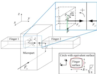
2) Stability according to a Fx perturbation (Fig. 5): Fx
induces a torque that may cause the rotation of the micropart. To prevent rotation, the admissible force Fx can be
approxi-mated. The surface in contact (between fingers and micropart) is square with 50µm of side. We consider the circle (R: radius) with the equivalent surface S, Fyi the applied force by the
finger to the micropart, P the uniform pressure induced byFyi,
dS the elementary contact surface,
→
dN and
→
dT the elementary normal and tangential force vector respectively (Fig. 6). Note that ℓ is the distance of the applied force Fx to the center of
the rotation and→n is the normal unit vector.
Fig. 6. Detailed scheme used to determine the maximum force Fx before
rotation.
Fyi = P.S (1) →
dN = P.dS.→n (2) The condition of non sliding at the considered pointPi is:
→ dT ≤µ.P.dS. → n (3)
According to the elementary torquedC, the integration on the complete surface gives the torque for one finger:
dC = ρ → dT => C = 2 3FyiµR (4) Whereρ is the distance between the point Pi and the axis of
theFy1 in Fig. 6. The condition of the stability is then:
Fx limit≤
4FyiµR
3ℓ (5)
With Eq. (5), the limit forceFx limitto ensure the stable grasp
according to Fy10= Fy20= 1200µN, µ = 0.3, ℓ=400µm and
R=28.2µm is estimated to be Fx limit ≤ 27.07µN. µ is the
friction coefficient. Then, Fy limit X≤
Fx limit
µ (6)
where Fy limit X refers to the limit of Fy induced by the
conditions of stability along X axis. Finally,
Fy limit X= 90µN (7)
3) Stability according to a Fy perturbation (Fig. 5): The
force Fy induces the displacement (linear displacement +
deflection + rotation) of the micropart between the two fingers but the micropart is maintained. The maximum admissible force Fy corresponds to the breaking of the fingers due to
evolution of the gripping forcesFy1andFy2in function of the
contact lateral forceFy, in order to determine a limit contact
force to ensure that the gripping forces are in the safe range in order not to break the microgripper fingers.
The model of the microgripper shown in Fig. 7 is used to study the evolution of the gripping forces in function of the lateral contact force Fy. Our previous studies showed the
Fig. 7. Microgripper model based on two-sensing-finger microgripper.
evolution of the gripping force evolution in the presence of lateral contact force for a rigid micropart. It was shown that the evolution of the gripping forces follows two steps, according to the contact between the microgripper fingers and the rigid micropart: planar contact and edge/vertex contact [21]. The planar contact is characterized by the linear displacement of the micropart and the edge/vertex contact by the combined linear translational displacement of the micropart along Y for small Fy force and rotation around X for higher Fy. For
that, a system of 5 non linear equations based on the contact forceFy enables to determine the evolution of gripping force.
This model has been established for a rigid micropart and experimentally validated. Based on that knowledge, Fig. 8 dis-plays the experimental behavior for a flexible micropart. These
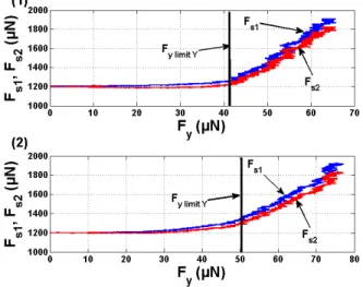
Fig. 8. Experimental results of gripping forces evolution Fs1 and Fs2
according to Fywith Fy10= Fy20= 1200µN, ℓ=500µm: (1) rigid micropart,
(2) flexible micropart
curves show that the gripping force on the two fingers are not equal when the lateral contact force is applied. The finger on the opposite side of the contact applies the biggest force to the micropart. Consequently, the side of the contact can be distinguished thanks to a two-sensing-finger microgripper.
Fig. 8 shows that the evolution of the gripping forces for the rigid (sepsfness around 1000N/m) and flexible (10N/m) microparts are quite similar in terms of contact force but different in terms of displacement. Some conclusions could be made:
• The evolution of the gripping forces follows also two
steps, according to the contact between the microgripper fingers and the flexible micropart: planar contact and edge/vertex contact.
• A better gripping stability can be induced. Indeed, the
displacement along Y before the rotation of the flexible micropart is bigger than for the rigid micropart. In addition, the limit of the contact force before the rotation of the object around X is Fy limit Y (Fy limit Y refers
to the limit of Fy induced by the conditions of stability
along Y axis). Fy limit Y is quite bigger for the flexible
micropart (50µN for the flexible micropart and 41.42µN for the rigid micropart).
• The evolution of the gripping forces does not follow a
slope in the planar contact. In fact, the evolution of the gripping forces is quite non linear in the planar contact. This non linearity is caused by the deflection of the flexible micropart. Otherwise, once the contact force Fy
is greater than 50µN, the micropart starts to rotate and then switches to the edge/vertex contact.
• The slope in the flexible micropart case (≈ 21.9) is
smaller than that for the rigid micropart (≈ 28.14) one during the edge/vertex contact.
These results show that the contact between the micropart and the microgripper fingers switches to the edge/vertex contact when Fy exceeds 50µN. Once the switching to the
edge/vertex contact happens, the evolution of the gripping forces in function of the contact force Fy increases rapidly.
Thus, a limit contact force Fy limit Y should be defined in
order to prevent the gripping forces for being bigger than 2mN (which is the sensing range of the microgripper fingers given by the manufacturer).
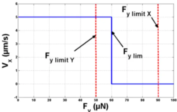
C. Guiding strategy
To achieve automated guiding tasks, it is necessary to establish a strategy. Two important parameters have been considered: the stability of the grasp (III-B) and the microscale specificities (III-A). The limits defined in the two previous sections will be considered in the guiding strategy.
The micropart motion is composed of an unconstrained displacement along X with a fixed velocity and a constrained displacement along Y. When the contact appears, three strate-gies exist to achieve the task:
• Stop the motion along X and correct the trajectory along
Y in order to break the contact. After that, the manipulator can be moved forward freely along X again.
• Move forward along X and correction along Y are
per-formed simultaneously. In that case, the gripping force must comply the condition in Eq. (5). This strategy is often used for the automated guiding tasks in macroscale.
• Stop the motion along X and correct the trajectory along
the contact.
First strategy may induce the presence of the pull-off force and a remaining contact even for Fy = 0 µN. It will be difficult to locate the contact break because the pull-off force is not constant, it indeed depends on many parameters [12]. Second and third strategies could be applied. Thus, an hybrid strategy of these two strategies is chosen. When a contact happens, Fy is small so Vx could be maximum. When Fy
is big (bigger than 90µN see Eq. (7)), the motion along X have to be stopped in order to prevent breaking or loosing the micropart. WhenFy is between 50µN and 90µN, the contact
between the gripping fingers and the micropart switches to the edge/vertex contact and then the evolution of the gripping forces increases rapidly. In addition, uncertainties on the distanceℓ and the friction coefficient µ could change the limit defined in (7) (FY limit X = 90µN ). Stopping the contact
at 60µN ensures that FY limit X remains bigger than 60µN
even with the uncertainties concerning the friction coefficient and the distance ℓ and then the stability along the X axis is ensured. Thus, Fy=60µN has been chosen as limit force
before switching OFF the motion along X because when Fy lim= 60µN , the gripping forces Fy1andFy2will increase
28% of their preload values. Such increase in gripping forces is accepted and the condition of stability along X given by the Eq. 7 remain valid. The gripping forces stay, as well, far away from the limit before breaking the microgripper fingers 2mN. The guiding strategy is summarized in Fig. 9.
Fig. 9. The guiding strategy proposed: Vx is the speed along X and Fyis
the contact force between the micropart and the rail.
IV. HYBRIDFORCE/POSITION CONTROL WITH FORCE ESTIMATION
In this section, an hybrid force/position control is proposed to achieve the control strategy developed in section III-C. For this purpose, a force estimator is developed to estimate the lateral contact forceFy.
A. Estimation of the lateral contact force by a two-sensing-finger microgripper
As seen in III-C, the guiding strategy depends on the lateral contact forceFy. For that,Fyshould be estimated. To estimate
the lateral contact forceFy, we use the force equilibrium along
Y (Eq. (8)) by using the information from two-sensing-finger in quasi-static mode (see Fig. 7).
Fy= Fy2−Fy1 (8)
Force sensors are generally coupled (in our case, the mea-surement depends on the force applied in theY direction but also along the Z direction). The expression of the measured forces by sensorized fingers are Fs1 = Fy1+ αFz1 (Finger
1) and Fs2 = Fy2 + αFz2 (Finger 2) where α is the
coupling coefficient.Fs1 andFs2are the measurement of the
microgripper sensing fingers. Consequently,
Fy = Fs2−Fs1−2αFz (9)
The coupling coefficient is small (α = 0.01 given by the manufacturer). Fz is also small during the contact, 2αFz
becomes negligible thus the contact forceFycan be evaluated:
Fy = Fs2−Fs1 (10)
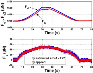
To validate this model, we use the experimental setup shown in Fig. 10. The proposed microgripper is used and a third force sensor applies a known lateral contact force. Fig. 11 shows the time evolution of the measured gripping forces (Fs1, Fs2)
and the comparison of the applied contact force Fy applied
by an external force sensor to the estimated contact force Fy estimated (using Eq. (10)). The estimated force is slightly
equal to the applied force in static part. The relative error is calculated and estimated to be smaller than 15%. Indeed, this error is due to the drift of the force sensors. These force sensors are hightech products and they work in a very small range of forces (maximum 2 mN). This result validates the estimation of the lateral contact force which can definitely be used for the control.
Fig. 10. Setup measurement of Fyby using an external force sensor.
B. Hybrid force/position control for achieving guiding task
To control the guiding tasks in automated mode, a control scheme of the system is established. Its objective is to maintain the lateral contact force under the fixed limitFy limit and to
reach the desired position along X. The position control along the rail and the lateral contact force have to be separated. Thus, the use of hybrid control [31], [32] combined with an internal position control [17] is chosen. This control structure is named external hybrid force/position control and was first proposed in [33]. In this section, a new controller based on the model proposed in [33] and taking into consideration the microscale specificities and the force limits developed in section III-C is proposed. The proposed block diagram (Fig. 12) enables to
Fig. 11. Estimation of the contact force Fy estimated by using Fs1 and
Fs2compared to the applied contact force Fy applied.
control the position along X and Z (move forward) and to remove the contact along Y . Indeed, Xd = [X, Y, Z] is the
input position of the 3 DOF robot, Fd is the input contact
force (Fd= 0 in our case). The matrix of selection S enables
to achieve the position control alongX and Z, and I-S enables to perform the force control along Y, where I is the identity matrix: S= 1 0 0 0 0 0 0 0 1
To avoid the sliding or rotation of the micropart during the
Fig. 12. Block diagram of the external hybrid force/position control during the guiding task.
guiding, it is required to directly detect the contact and to start the correction along theY in order to reduce the lateral contact force under the fixed limit (Fy lim= 60µN). At the same time,
we keep going forward along X. The E block is an “Enable control” which stops the motion along X when the lateral contact force is bigger than the upper limit (Fy lim) in order
to be able to ensure the guiding task (see III-C). The details of E are shown in Fig. 13. A strategy to achieve automated guiding tasks based on hybrid force/position control have been integrated. Position Control Laws (PCL) are Proportional
Fig. 13. Detailed of the enable control block E.
Integral controllers which are internal to the positioning stages. Investigations are focused on the Force Control Law (FCL).
The use of Incremental Control is proposed to ensure the control of the contact force. It’s a simple and robust controller which the correction speed could be easily controlled with ensuring stability. The use of this type of controller is a first step that guarantees the desired performances. The study is performed for different kinds of perturbations. The complete system is not considered to be linear time invariant (LTI) due to the play between the micropart and the rail and the distance of the contact (ℓ) uncertainty [34]. Thus, conventional studies based on LTI theories are not relevant.
In the robotic field, the use of this incremental controller enables easy and fast set up of parameters and reduces the risks of breaking the microparts or the manipulator. Details of the controller structure are given in Fig. 14. It is composed of a dead zone for rejecting the sensor noise measurement (10µN), the sign operator for indicating the direction of the increment, and the memory operation for enabling the relative positioning.
Fig. 14. Block diagram of the incremental controller (FCL).
This nonlinear controller enables to set the velocity of the correctionVcorr in accordance to the sampling frequency
Fsamplingand the incrementStepincr. It can be calculated by
Vcorr = Fsampling.Stepincr. The magnitude of this step has
to be smaller than the play for ensuring the stability.
C. Incremental Control
The objective is to apply the incremental controller as for the Force Control Law (FCL). The control scheme is implemented on a 1104 Dspace board with a sampling frequencyFsampling
= 1KHz. This sampling frequency is a trade off between high speed sampling and experimental limitations.
In the following, the performance of the controller will be tested for different incremental stepsStepincr. The robustness
of the controller will be tested for the misalignment between the rail axis and the guiding axis but also for some perturba-tions on each side of the rail.
The dead zone of the FCL is fixed to 15µN which is slightly bigger than the range of noise (10 µN). FCL is switched on (Enable control) when the estimated contact force becomes bigger than 15 µN, the correction acts and the lateral contact force is brought back smaller than 15µN. The move forward motion stops when the lateral contact force is bigger than 60 µN which is the upper limit defined in the guiding strategy presented in Fig. 9. The increase of velocity correction Vcorr
induces a time reduction to cancel the perturbation.Vcorrmust
be faster than the increase of contact force velocity to prevent from stopping moving alongX. Otherwise, if the increase of contact force is faster than the Vcorr, we may reach the upper
limitFy limitand in this case, the enable bloc will stop moving
along X and the FCL controller will reduce the contact force below 60µN.
V. AUTOMATED GUIDING TASKS ANDEXPERIMENTAL RESULTS
In this section, automated guiding tasks are tested and ex-perimental investigations are performed to test the controller’s performances and the guiding strategy.
A. Automated guiding task with misalignment between the rail axis and the guiding axis
To experiment the automated guiding task including a misalignment between the rail axis and the move forward axis, we introduce a ramp by moving yp. During this phase, the FCL
controller is always “ON” and can directly work. Considering the perturbation displacement and the move forward displace-ment, an equivalent angle γ of misalignment is estimated to 32.8◦
byγ = tan−1
(∆yp/∆xn).
Results are shown in Fig. 151. It is observed that when the
contact occurs, the estimated force gradually increases to the fixed limit. The controller starts the correction to maintain this force under the authorized limit (15µN). We can also observe that during the guiding task, gripping forces are maintained in the tolerable range avoids the risk of breaking microparts and guarantees the stability of the micropart between microgripper fingers. The increase of the preload is estimated to 1.9% for 15µN offset contact force. This small increase is the cause of the micropart flexibility. Indeed, a big displacement has to be applied to the micropart in order to increase the force with a relative big value. The desired position along X is reached without micropart sliding thus the task is successfully achieved.
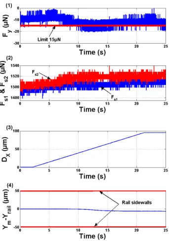
B. Automated guiding task with step perturbation at each side of the rail
The robustness of the guiding task control is tested by intro-ducing a step perturbation during the task. Left side contact and right side contact are successively generated during the move forward motion. The FCL controller is already “ON” at
1Coordinate frames and positioning stages are detailed in Fig.3
Fig. 15. Experimental results of an automated guiding task: (1) Lateral contact force estimation Fy = Fs1− Fs2 (2) gripping forces, (3) move
forward motion along X with 5µm/s velocity, (4) Position of the point Om
(Ym) of the micropart in Fig. 3 compared to the rail position along Y (Yrail).
the beginning of the task. The fixed limit is also 15µN. Results are shown in Fig. 16. It was shown that the established control scheme is able to reject step perturbations that are applied at t=6s and t=17s: the move forward motion is stopped to ensure the stability of the grasp when the estimated contact force is over 60µN (Enable control effect). These results are shown for a velocity correction Vcorr = 10µm/s with step increment
Stepincr= 10nm andFsampling= 1000Hz. The rejection time
is 5s which is quite big. In order to reduce the rejection time, we have two possibilities: one is to increase the step increment, another is to increase the sampling frequency. If we increase the step increment with a big value, the velocity correction will be so fast and we won’t see the effect of the perturbation. In order to calculate the response time of the controller, we have switched OFF the FCL controller once we have applied the perturbation and then we have turned it ON. Fig. 17 shows the response of the system to a step perturbation for a velocity correctionVcorr= 1mm/s with step incrementStepincr= 1µm
andFsampling= 1000Hz. Fig. 17 shows that the response time
is 75ms which is near the response time of the correction stage. The desired position along X is reached without micropart sliding despite the big step perturbation displacement applied. Thus, the task is successfully achieved.
Fig. 16. Experimental results of an automated guiding task: (1) lateral contact force estimation (Fy = Fs2− Fs1), (2) gripping forces, (3) move forward
motion along X with 5µm/s velocity, (4) Position of the point Om(Ym) of
the micropart in Fig. 3 compared to the rail position along Y (Yrail).
C. Behavior of the micropart during guiding task
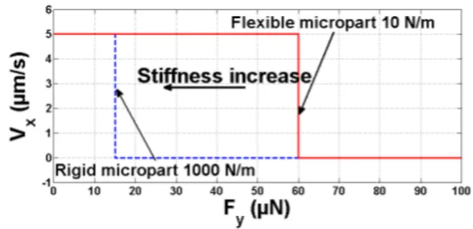
During the guiding task, the proposed control scheme has ensured the stability of the tasks. As shown in section V-A and V-B, the performances were robust enough for the misalignment between the axis (rail axis and guiding axis) and in presence of big step perturbation. The FCL controller was able to deal with a 100µm of displacement (see Fig. 17) after the contact appears (100µN of contact force) which is a big displacement (almost the same of the rail width). Fig. 16 shows that the Enable control appears 900ms after application of the step perturbation. This is due to the flexibility of the micropart. Indeed, for a rigid micropart the limit force will be exceeded for a small contact between the rail and the micropart. Otherwise, the deflection of the flexible micropart induces a smaller variation of gripping forces than for the rigid micropart. Consequently, the automated guiding task stability increases with the flexibility of the micropart. The proposed guiding strategy is able to accomplish an automated guiding task for both a flexible and a rigid micropart. However, the rigid micropart could be lost if the limit is fixed to 60 µN because a contact force of 60µN corresponds to an increase of 50% (see Fig. 8) on the gripping forces which will be close to
Fig. 17. Experimental results of an automated guiding task: (1) lateral contact force estimation (Fy= Fs2− Fs1), (2) gripping forces, (3) move forward
motion along X with 5µm/s velocity, (4) Position of the point Om(Ym) of
the micropart in Fig. 3 compared to the rail position along Y (Yrail).
the limit of the force sensors. Thus, the limit of going forward along X should be fixed carefully depending on the micropart sepsfness as shown in Fig. 18. The sepsfness of the micropart should be known or estimated before starting the experiments. Another option is to use an adaptive controller in order to estimate the sepsfness of the micropart and to use it for the controller. The influence of the sepsfness of the object on the guiding strategy is summarized in Fig. 18.
VI. CONCLUSION
A study of hybrid force/position control based guiding task at the microscale is proposed in this paper. A guiding strategy and experimental validations of the automated guiding task are proposed. A flexible micropart of 50 x 50 x 2000µm3
in size is manipulated and a few tens of µN force control is achieved in parallel to position control with a nanometer resolution stage. An experimental model of the behavior of the flexible micropart between the microgripper fingers has been established. The lateral contact force is estimated by using a two-sensing-finger microgripper and it is used in an external hybrid force/position control. A guiding strategy is proposed taking into consideration the non linearity of the system and the microscale specificities. It has been observed that the rejection time of the force control law reaches the response time of the correcting stage during the experimen-tal measurements (≈ 75ms). The incremenexperimen-tal controller has been validated and its robustness shown by rejecting step perturbations at each side of the rail. The controller has dealt with a relative big displacement perturbations (100µm i.e. 2 times the cross section of the manipulated object) which is near to the width of the rail. Automated guiding tasks with a misalignment angle γ of 32.8◦
between the rail axis and the guiding axis have been experimentally performed. The slight increase of gripping forces (1.9% compared to preload) during the task authorizes to perform it with fragile microparts, enables to ensure fine grasping of the micropart and provides more dexterity of the grasp.
This whole study shows that the use of hybrid force/position control to achieve automated microassembly tasks constitutes a promising approach. The estimated contact force was per-formed for 1 DOF and an additional force or torque infor-mation will be studied to perform more complex and other delicate automated microassembly tasks like insertion.
ACKNOWLEDGMENT
These works have been funded by the region Franche-Comte. We would like to acknowledge Mr. David Guibert for technical support.
REFERENCES
[1] K. Aljasem, L. Froehly, A. Seifert, and H.Zappe, “Scanning and tunable micro-optics for endoscopic optical coherence tomography,” Journal of
Microelectromechanical Systems, vol. 20, pp. 1462 – 1472, Dec 2011. [2] K. Aljasem, A. Werber, A. Seifert, and H. Zappe, “Fiber optic tunable
probe for endoscopic optical coherence tomography,” Journal of Optics
A: Pure and Applied Optics, vol. 10, no. 4, p. 044012, 2008. [Online]. Available: http://stacks.iop.org/1464-4258/10/i=4/a=044012
[3] S. Waldis, F. Zamkotsian, P.-A. Clerc, W. Noell, M. Zickar, and N. de de Rooij, “Arrays of high tilt-angle micromirrors for multiobject spectroscopy,” IEEE Journal of Selected Topics in Quantum Electronics, vol. 13, no. 2, pp. 168 – 176, March-april 2007.
[4] D. Tolfree and M. J. Jackson, Commercializing Micro-Nanotechnology
Products. CRC Press, 2006.
[5] A. N. Das, P. Zhang, W. H. Lee, H. Stephanou, and D. Popa, “µ3
: Multiscale, deterministic micro-nano assembly system for construction of on-wafer microrobots,” in IEEE International Conference on Robotics
and Automation, Roma, Italia, 2007.
[6] B. Tamadazte, N. L.-F. Piat, and S. Demb´el´e, “Robotic microma-nipulation and microassembly using monoview and multiscale visual servoing,” IEEE/ASME Transactions on Mechatronics, vol. 16 Issue: 2, pp. 277 – 287, April 2011.
[7] V. Sariola, M. Jaaskelainen, and Q. Zhou, “Hybrid microassembly com-bining robotics and water droplet self-alignment,” IEEE Transactions on
Robotics, vol. 26, pp. 965–977, 2010.
[8] Z. Lu, P. C. Y. Chen, A. Ganapathy, G. Zhao, J. Nam, G. Yang, E. Burdet, C. Teo, Q. Meng, and W. Lin, “A force-feedback control system for micro-assembly,” Journal of Micromechecanics Microengineering, vol. 16, pp. 1861–1868, 2006.
[9] H. Xie and S. R´egnier, “Three-dimensional automated micromanipu-lation using a nanotip gripper with multi-feedback,” Journal of
Mi-cromechecanics Microengineering, vol. 19 075009, 2009.
[10] L. Wang, L. Ren, J. Mills, and W. Cleghorn, “Automated 3-d micro-grasping tasks performed by vision-based control,” IEEE Transactions
on Automation Science and Engineering, vol. 7, pp. 417 – 426, 2010. [11] Y. Anis, M. Holl, and D. Meldrum, “Automated selection and placement
of single cells using vision-based feedback control,” IEEE Transactions
on Automation Science and Engineering, vol. 7, pp. 598 – 606, July 2010.
[12] K. Rabenorosoa, C. Cl´evy, P. Lutz, M. Gauthier, and P. Rougeot, “Measurement of pull-off force for planar contact at the microscale,”
Micro Nano Letters, vol. 4, pp. 148 –154, 2009.
[13] C. Cl´evy, M. Rakotondrabe, and N. Chaillet, Signal Measurement and
Estimation Techniques for Micro and Nanotechnology, I. 978-1-4419-9945-0, Ed. Springer, 2011.
[14] M. C. Carrozza, A. Eisinberg, A. Menciassi, D. Campolo, S. Micera, and P. Dario, “Towards a force-controlled microgripper for assembling biomedical microdevice,” Journal of Micromechanics and
Microengi-neering, vol. 10, pp. 271– 276, 2000.
[15] A. N. Reddy, N. Maheshwari, D. K. Sahu, and G. K. Ananthasuresh, “Miniature compliant grippers with vision-based force sensing,” IEEE
Transactions on Robotics, vol. 26, pp. 867–877, 2010.
[16] M. Rakotondrabe and I. A. Ivan, “Development and force/position control of a new hybrid thermo-piezoelectric microgripper dedicated to micromanipulation tasks,” IEEE Transactions on Automation Science
and Engineering, vol. 8, pp. 824 – 834, 2011.
[17] R. Volpe and P. Khosla, “A theoretical and experimental investigation of explicit force control strategies for manipulators,” IEEE Transactions
on Automatic Control, vol. 38, pp. 634–1650, 1993.
[18] Y. Zhou, B. J. Nelson, and B. Vikramaditya, “Fusing force and vision feedback for micromanipulation,” in IEEE International Conference on
Robotics and Automation, 1998, pp. 1220– 1225.
[19] J. Wason, W. Gressick, J. T. Wen, J. Gorman, and N. Dagalakis, “Multi-probe micro-assembly,” in IEEE Conference on Automation Science and
Engineering, 2007, pp. 63–68.
[20] W. Zesch and R. S. Fearing, “Alignment of microparts using force controlled pushing,” The International Society for Optical Engineering, vol. 3519, pp. 148– 156, 1998.
[21] K. Rabenorosoa, C. Cl´evy, Q. Chen, and P. Lutz, “Study of forces during microassembly tasks using two-sensing-fingers grippers,” IEEE/ASME
Transactions on Mechatronics, vol. 17 Issue 5, pp. 811 – 821, Oct. 2012.
[22] S. Bargiel, K. Rabenorosoa, C. Cl´evy, C. Gorecki, and P. Lutz, “Towards micro-assembly of hybrid moems components on a reconfigurable silicon free-space micro-optical bench,” Journal of Micromechanics and
Microengineering, vol. 20, pp. 1–12, 2010.
[23] D. Popa, W. H. Lee, R. Murthy, A. Das, and H. Stephanou, “High yield automated mems assembly,” in IEEE International Conference on
Automation Science and Engineering (CASE), 2007, pp. 1099 – 1104. [24] K. Rabenorosoa, C. Cl´evy, and P. Lutz, “Active force control for robotic
micro-assembly: Application to guiding tasks,” in IEEE International
Conference on Robotics and Automation, May 2010, pp. 2137–2142. [25] D. Cappelleri, G. Piazza, and V. Kumar, “A two dimensional
vision-based force sensor for microrobotic applications,” Sensors & Actuators
A: Physical, vol. 171, pp. 340 – 351, 2011.
[26] F. Arai, D. Andou, Y. Nonoda, T. Fukuda, H. Iwata, and K. Itoigawa, “In-tegrated microendeffector for micromanipulation,” IEEE/ASME
Transac-tions on Mechatronics, vol. 3, pp. 17 – 23, 1998.
[27] Y. Shen, X. Ning, and W. J. Li, “Contact and force control in mi-croassembly,” in IEEE Internation Symposium of Assembly and Task
Planning, 2003, pp. 60–65.
[28] F. Beyeler, A. Neild, S. Oberti, D. J. Bell, Y. Sun, J. Dual, and B. J. Nelson, “Monolithically fabricated microgripper with integrated force sensor for manipulating microobjects and biological cells aligned in an ultrasonic field,” Journal of Microelectromechanical Systems, vol. 16, pp. 7–16, 2007.
[29] M. T. Mason, “Compliance and force control for computer controlled manipulators,” Ph.D. dissertation, Massachusetts Institute of Technology, 1979.
[30] T. Lefebvre, J. Xiao, H. Bruyninckx, and G. de Gersem, “Active compliant motion: a survey,” Advanced Robotics, vol. 19, pp. 479–499, 2005.
[31] M. Raibert and J. J. Craig, “Hybrid position/force control of manipu-lators,” Transactions of ASME, Journal of Dynamic Systems,
Measure-ment, and Control, vol. 102, pp. 126–133, 1981.
[32] W. D. Fisher and M. S. Mujtaba, “Hybrid position/force control: A correct formulation,” International Journal of Robotics Research, vol. 11, pp. 299–311, 1992.
[33] V. Perdereau and M. Drouin, “A new scheme for hybrid force-position control,” Lecture Notes in Control and Information Sciences,
Experi-mental Robotics IV, vol. 187, pp. 150–159, 1993.
[34] K. Rabenorosoa, C. Cl´evy, and P. Lutz, “Hybrid force/position control applied to automated guiding tasks at the microscale,” in IEEE/RSJ
International Conference on Intelligent Robots and Systems, October 2010, pp. 4366 – 4371.
Bilal Komati holds a MS degree in Control and Systems from Sup´elec, Paris, France and an Electri-cal Engineer degree from the Lebanese University, Beirut, Lebanon in 2011.
Since 2011, he has been a PhD student in Auto-matic Control and Microrobotics at the University of Franche-Comt´e, Besanc¸on, France. His research interests include design and control of microrobots, micromechatronic systems and microassembly in the department of Automatic Control and Micro-Mechatronic Systems at FEMTO-ST institute.
Kanty Rabenorosoa holds a MS degree (2007) in Electrical Engineering from INSA Strasbourg, France and a Ph.D in Microrobotics and Automatic (2010) from Universit´e de Franche-Comt´e. He was a temporary research assistant at FEMTO-ST Institute in AS2M department (Automatic Control and Micro-Mechatronic Systems) from october 2010 to august 2011. He was a postdoc fellow at LIRMM in DEX-TER team between september 2011 to August 2012. He is currently associate professor at FEMTO-ST Institute in AS2M department. His research interests are microrobotic and micromechatronic systems for medical applications in MINAROB team.
C´edric Cl´evy graduated from the Ecole Normale Sup´erieure de Cachan, France, in 2001, received the Master degree in mechanical engineering, automat-ics and automation, in 2002, and the Ph.D. degree in automatics, in 2005.
Since 2006, he has been an Associate Professor at the FEMTO-ST Institute, University of Franche-Comt´e, Besanc¸on, France. His current research in-terests include design and control of microrobotics, microfactories, and microassembly systems oriented to optical components.
Philippe Lutz joined the University of Franche-Comt´e, Besanon, as Professor in 2002. He was the head of the research group ”Automated Sys-tems for Micromanipulation and Micro-assembly” of the AS2M department of FEMTO-ST from 2005 to 2011. He is currently the Director of the PhD graduate school of Engineering science and Mi-crosystems with more than 400 PhD students. His research activities are focussed on the design and the control of MicroMechatronic Systems. P. Lutz received several awards of IEEE, is author of over 60 refereed publications, serves as associate editor for the IEEE Transaction on Automation Science and Engineering (T-ASE) and and is an active member in the IEEE Robotics and Automation Society (RAS) Committee on Micro-Nano Robotics. He received the Engineer degree from the National School of Mechanics and Microtechnology (ENSMM) in 1990 and the Ph.D. Degree of the University of Franche-Comt´e in Automation and Computer Science in 1994. He was Associate Professor in the INSA of Strasbourg since 1994 until 2002.