UNIVERSITÉ DE SHERBROOKE Faculté de génie
Département de génie électrique et de génie informatique
electric – Transport, Energy Storage and Conversion laboratory
Canada
UNIVERSITÉ DE LILLE École Doctorale des Sciences
Pour l'Ingénieur (ED SPI)
Laboratoire d'Electrotechniques et d'Electronique de Puissance de Lille
France
S
TRATEGIES DEG
ESTION D’É
NERGIE POURV
ÉHICULESÉ
LECTRIQUES ETH
YBRIDE AVECS
YSTÈMESH
YBRIDE DES
TOCKAGE D’É
NERGIEE
NERGYM
ANAGEMENTS
TRATEGIES OFE
LECTRIC ANDH
YBRIDV
EHICLESS
UPPLIED BYH
YBRIDE
NERGYS
TORAGES
YSTEMSThèse de doctorat Spécialité : génie électrique
par
NGUYỄN Bảo-Huy
Soutenue le 18 septembre 2019 devant le jury composé de : M. Loïc BOULON Professeur, Université du Québec à
Trois-Rivières, QC, Canada
Rapporteur M. Alain BOUSCAYROL Professeur, Université de Lille,
France
Directeur de thèse M. Ruben GONZALEZ-RUBIO Professeur, Université de
Sherbrooke, QC, Canada
Rapporteur UdeS M. Ronan GERMAN Maître de conférences, Université
de Lille, France
Co-encadrant Mme Marie-Cécile PÉRA Professeur, Université de
Franche-Comté, France
Rapporteur Mme Manuela SECHILARIU Professeur, Université de
technologie de Compiègne, France
Président du jury M. Rochdi TRIGUI Directeur de recherche, IFSTTAR,
France
Examinateur M. João Pedro F. TROVÃO Professeur, Université de
Sherbrooke, QC, Canada
Directeur de thèse
A problem well put is half solved.
John Dewey
Everything should be made as simple as possible, but not simpler.
(supposed to be) Albert Einstein
Của tin, gọi một chút này làm ghi.
M
EMBRES DU JURY
M. Loïc BOULON, Rapporteur
Professeur, Université du Québec à Trois-Rivières, QC, Canada
M. Alain BOUSCAYROL, Directeur de thèse Professeur, Université de Lille, France
M. Ruben GONZALEZ-RUBIO, Rapporteur UdeS Professeur, Université de Sherbrooke, QC, Canada
M. Ronan GERMAN, Co-encadrant Maître de conférences, Université de Lille, France
Mme Marie-Cécile PÉRA, Rapporteur Professeur, Université de Franche-Comté, France
Mme Manuela SECHILARIU, Président du jury Professeur, Université de technologie de Compiègne, France
M. Rochdi TRIGUI, Examinateur
Directeur de recherche, Institut français des sciences et technologies des transports, de l'aménagement et des réseaux, France
M. João Pedro F. TROVÃO, Directeur de thèse Professeur, Université de Sherbrooke, QC, Canada
Acknowledgements
I am writing these acknowledgements shortly with simple words. It is due to the Asian philosophy: let the blanks tell more.
This thesis has been carried out in four years under the supervision of my advisory board, whom my first words of acknowledgements are dedicated to. I would like to thank M. Alain BOUSCAYROL to supervise my thesis at L2EP, Université de Lille, France. I cannot count how many things I have learnt from him. With me, Alain is the best teacher in the world. I would like to thank M. João Pedro F. TROVÃO to supervise my thesis at e-TESC laboratory, Université de Sherbrooke, Canada. I cannot imagine how I could deal with the difficulties during my PhD life without him. With me, João is the kindest professor in the world. I would like to thank M. Ronan GERMAN to advise me on the work of the thesis. Ronan is the most interesting advisor I have ever known.
I would like to acknowledge the jury of my thesis defense. I would like to thank Mme Manuela SECHILARIU, Professor at Université de technologie de Compiègne, France for being the president of the jury. I would like to thank Mme Marie-Cécile PÉRA, Professor at Université de Franche-Comté, France and M. Loïc BOULON, Professor at Université du Québec à Trois-Rivières, Canada for being the reviewers (rapporteurs) of the thesis. I would like to thank M. Ruben GONZALEZ-RUBIO, Professor at Université de Sherbrooke, Canada for being the UdeS reviewer of the thesis. I would like to thank M. Rochdi TRIGUI, Director of research at IFSTTAR, France for being the examiner of the thesis. All of their questions, discussions, and suggestions are in the positive directions to help me improving my work. I also appreciate their encouragements with positive comments on the reports and during the thesis defense.
In France, I have worked in L2EP which is a dynamical and comfortable research environment. I would like to thank Mme Betty LEMAIRE-SEMAIL – the Director of the laboratory – and all the professors and staffs of L2EP for developing this environment.
I have been also with Hanoi University of Science and Technology (HUST), Vietnam. Hanoi is where I was born; and HUST is the hometown of my academic life. I would like to thank thầy TẠ Cao Minh – the father of my academic life. My thanks go to chị Hà, anh Thành, anh Quang, Hùng, and all my teachers and friends at HUST.
I have had a great time of joyfulness at L2EP with my friends, especially in P2 and ESPRIT. Thank you, Abdoulaye, Anatole, Clément, David, Emna, Florentin, Florian, Gianluca, Guillaume, Hugo, Houssein, Jérôme, Jalal, Jian, Kaibo, Kévin, Laure, Laurent, Loris, Marc, Meryeme, Nicolas, Oriol, Rihab, Ryan, Shingo, Smail, Sylvain, and you guys in L2EP. I will miss our time, especially with lunch, coffee, and Tarot!
My life in Lille has been colorful thanks to my Vietnamese friends. Thank you, anh Kỳ, anh Bình, anh Long, Tân; and thank Jinlin. Thank you, Trang and Huy, my so-sweet neighbors. Thank you too, Lê.
It has been also a great time at e-TESC lab with my friends there. Thank you, Adrien, Ahmad, Alexandre, Félix, Mandé, Mebrahtom, Pascal. Special thanks to you, Chadi!
My thanks go to the Vietnamese community in Sherbrooke. Thank you, chú Hiến, chị Vân, anh Cường, chị Hà, chị Hiền, anh Khôi, Bảo, Dũng, Huệ, Kiên, Long, Thuỷ, Tính, Tuyền.
My family always backs me without any need of thank-you words. This thesis is dedicated to the two women of my life: my mother and my wife.
Résumé
Les véhicules électriques et hybrides font partie des éléments clés pour résoudre les problèmes de réchauffement de la planète et d'épuisement des ressources en combustibles fossiles dans le domaine du transporte. En raison des limites des différents systèmes de stockage et de conversion d’énergie en termes de puissance et d'énergie, les hybridations sont intéressantes pour les véhicules électriques (VE). Dans cette thèse, deux hybridations typiques sont étudiées • un sous-système de stockage d'énergie hybride combinant des batteries et des
supercondensateurs (SC) ;
• et un sous-système de traction hybride parallèle combinant moteur à combustion interne et entraînement électrique.
Ces sources d'énergie et ces conversions combinées doivent être gérées dans le cadre de stratégies de gestion de l'énergie (SGE). Parmi celles-ci, les méthodes basées sur l'optimisation présentent un intérêt en raison de leur approche systématique et de leurs performances élevées. Néanmoins, ces méthodes sont souvent compliquées et demandent beaucoup de temps de calcul, ce qui peut être difficile à réaliser dans des applications réelles.
L'objectif de cette thèse est de développer des SGE simples mais efficaces basées sur l'optimisation en temps réel pour un VE et un camion à traction hybride parallèle alimentés par des batteries et des SC (système de stockage hybride). Les complexités du système étudié sont réduites en utilisant la représentation macroscopique énergétique (REM). La REM permet de réaliser des modèles réduits pour la gestion de l'énergie au niveau de la supervision. La théorie du contrôle optimal est ensuite appliquée à ces modèles réduits pour réaliser des SGE en temps réel. Ces stratégies sont basées sur des réductions de modèle appropriées, mais elles sont systématiques et performantes. Les performances des SGE proposées sont vérifiées en simulation par comparaison avec l’optimum théorique (programmation dynamique). De plus, les capacités en temps réel des SGE développées sont validées via des expériences en « hardware-in-the-loop » à puissances réduites. Les résultats confirment les avantages des stratégies proposées développées par l'approche unifiée de la thèse.
Mots-clés : véhicule électrique hybride, véhicule électrique, stratégie de gestion de l'énergie,
optimisation en temps réel, batterie, supercondensateur (SC), système de stockage d'énergie hybride, représentation énergétique macroscopique (REM), simulation « hardware-in-the-loop (HIL) ».
Abstract
Electric and hybrid vehicles are among the keys to solve the problems of global warming and exhausted fossil fuel resources in transportation sector. Due to the limits of energy sources and energy converters in terms of power and energy, hybridizations are of interest for future electrified vehicles. Two typical hybridizations are studied in this thesis:
• hybrid energy storage subsystem combining batteries and supercapacitors (SCs); and • hybrid traction subsystem combining internal combustion engine and electric drive. Such combined energy sources and converters must be handled by energy management strategies (EMSs). In which, optimization-based methods are of interest due to their high performance. Nonetheless, these methods are often complicated and computation consuming which can be difficult to be realized in real-world applications.
The objective of this thesis is to develop simple but effective real-time optimization-based EMSs for an electric car and a parallel hybrid truck supplied by batteries and SCs. The complexities of the studied system are tackled by using Energetic Macroscopic Representation (EMR) which helps to conduct reduced models for energy management at the supervisory level. Optimal control theory is then applied to these reduced models to accomplish real-time EMSs. These strategies are simple due to the suitable model reductions but systematic and high-performance due to the optimization-based methods. The high-performances of the proposed strategies are verified via simulations by comparing with off-line optimal benchmark deduced by dynamic programming. Moreover, real-time capabilities of these novel EMSs are validated via experiments by using reduced-scale power hardware-in-the-loop simulation. The results confirm the advantages of the proposed strategies developed by the unified approach in the thesis.
Keywords: Hybrid electric vehicle (HEV), electric vehicle (EV), energy management strategy
(EMS), real-time optimization, battery, supercapacitor (SC), hybrid energy storage system (H-ESS), Energetic Macroscopic Representation (EMR), Hardware-In-the-Loop (HIL) simulation.
Table of contents
Introduction ... 1
1. Background and literature review ... 4
1.1.Context of the thesis ... 4
1.1.1. Electrified vehicles: why electric and why not yet full electric? ... 4
1.1.2. Energy management strategies: why and where is the thesis? ... 10
1.2.State-of-the-art review on energy management strategies ... 14
1.2.1. Rule-based methods ... 15
1.2.2. Optimization-based methods ... 20
1.3.Objective and approach of the thesis ... 32
1.3.1. Objective of the thesis ... 32
1.3.2. Methodology of the thesis ... 33
1.4.Conclusion ... 36
2. Real-time optimization-based energy management strategy for a battery/supercapacitor electric vehicle ... 37
2.1.Model for energy management strategy ... 37
2.1.1. Studied system ... 37
2.1.2. Modeling and energetic macroscopic representation of the studied system ... 38
2.1.3. Local control of the studied system ... 43
2.1.4. Model modification for energy management strategy development ... 46
2.2.Optimal benchmark using dynamic programming ... 51
2.2.1. Backward representation ... 51
2.2.2. Dynamic programming implementation ... 52
2.3.Real-time strategy based on Hamiltonian minimization ... 52
2.3.1. Approach ... 53
2.3.2. Strategy development ... 53
2.3.3. Co-state variable physical meaning and determination ... 55
2.3.4. Strategy implementation ... 57
2.4.Simulations and results ... 57
2.4.1. Examined system ... 57
2.4.2. Results and discussions ... 60
2.5.Experiments and results ... 64
2.5.1. Experimental system ... 64
2.5.2. Results and discussions ... 69
3. Real-time optimization-based energy management strategy for a
battery/supercapacitor parallel hybrid truck ... 73
3.1.Model for energy management strategy ... 73
3.1.1. Studied system ... 73
3.1.2. Modeling and energetic macroscopic representation of the studied system ... 74
3.1.3. Local control of the studied system ... 77
3.1.4. Model modification for energy management strategy development ... 80
3.2.Optimal benchmark using dynamic programming ... 87
3.2.1. Backward representation ... 87
3.2.2. Dynamic programming implementation ... 88
3.3.Real-time strategy based on linear quadratic regulator ... 89
3.3.1. Approach ... 89
3.3.2. Strategy development ... 91
3.3.3. Strategy implementation ... 94
3.4.Simulations and results ... 94
3.4.1. Examined system ... 94
3.4.2. Results and discussions ... 97
3.5.Experiments and results ... 101
3.5.1. Experimental setup ... 101
3.5.2. Results and discussions ... 107
3.6.Conclusion ... 111
General conclusion ... 112
Appendix... 115
A.1.Energetic Macroscopic Representation ... 115
A.2.Additional study on a multi-objective approach for optimal energy management of hybrid energy storage subsystems for electric vehicles ... 119
A.3.Linearity and non-linearity of the studied systems models ... 127
A.4.Additional simulation and experimental results of the proposed Hamiltonian minimization-based current distribution strategy for battery/SC EV... 129
A.5.Additional simulation and experimental results of the proposed LQR-based torque distribution strategy for battery/SC parallel hybrid truck ... 133
List of figures
Figure 1.1: A brief history of the interest on EVs in terms of power and energy. ... 5
Figure 1.2: Power and energy densities comparison of common sources used for vehicles (adapted from [Trovão 2017; Werkstetter 2015]). ... 6
Figure 1.3: General configuration of series HEVs. ... 7
Figure 1.4: General configuration of parallel HEVs. ... 8
Figure 1.5: A configuration of series-parallel HEVs. ... 8
Figure 1.6: General configuration of passive battery/SC H-ESS. ... 9
Figure 1.7: General configuration of semi-active battery/SC H-ESS. ... 10
Figure 1.8: General configuration of active battery/SC H-ESS. ... 10
Figure 1.9: The map of MEGEVH network [MEGEVH 2019]. ... 11
Figure 1.10: Scientific context of the thesis within MEGEVH network. ... 12
Figure 1.11: Scientific context of the thesis within Canada Research Chair program. ... 13
Figure 1.12: EMR-based general description of multi-source vehicles with EMSs. ... 14
Figure 1.13: Classification of energy management methods. ... 15
Figure 1.14: General description of EMSs with frequency-based methods. ... 16
Figure 1.15: General description of EMSs with mode-based methods. ... 18
Figure 1.16: General description of EMSs with feedback control-based methods. ... 18
Figure 1.17: General description of EMSs with artificial neural network-based methods. ... 20
Figure 1.18: General description of EMSs with dynamic programming. ... 22
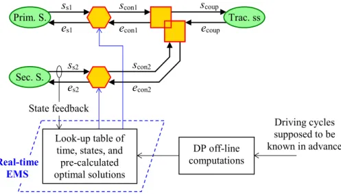
Figure 1.19: General description of real-time EMSs with DP solution-based methods. ... 26
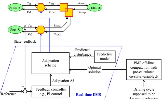
Figure 1.20: General description of real-time EMSs with PMP-based methods. ... 27
Figure 1.21: General description of EMSs with model predictive control. ... 29
Figure 1.22: Illustration of receding horizon principle... 29
Figure 1.23: General description of EMSs with meta-heuristic optimization. ... 31
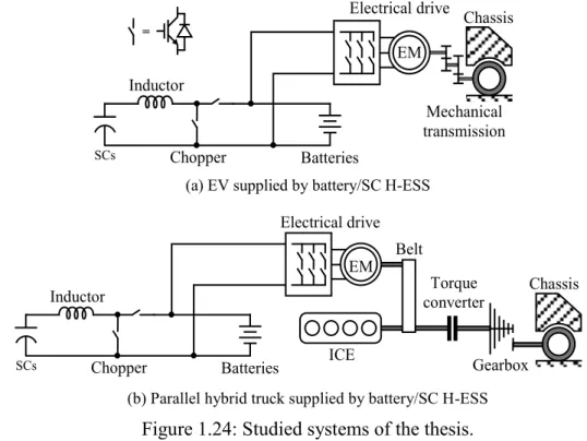
Figure 1.24: Studied systems of the thesis. ... 33
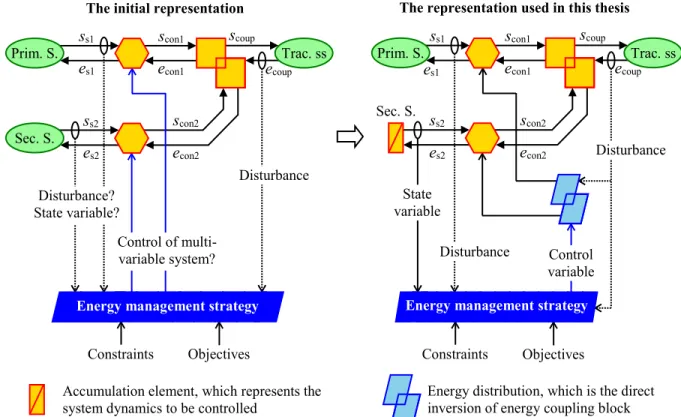
Figure 1.25: EMR-based general system representation used in the thesis... 34
Figure 1.26: Backward representation deduction from forward representation in the thesis. ... 35
Figure 1.27: Methodology for thesis development. ... 36
Figure 2.1: Studied system: an EV supplied by a battery/SC H-ESS. ... 38
Figure 2.2: EMR of the studied EV components... 38
Figure 2.3: Batteries equivalent circuit model... 39
Figure 2.4: SCs equivalent circuit model. ... 40
Figure 2.5: Inductor equivalent circuit model. ... 40
Figure 2.7: Tuning paths and control paths for local control of the studied battery/SC EV. .... 43
Figure 2.8: Velocity controller as an indirect inversion of the vehicle chassis. ... 44
Figure 2.9: EMR and inversion-based control of the studied battery/SC EV. ... 45
Figure 2.10: Model reductions of DC/DC converter assuming perfect control performances. . 47
Figure 2.11: Model transformation to highlight the considered dynamics at supervisory level. ... 48
Figure 2.12: Model transformation to highlight the disturbance at supervisory level. ... 48
Figure 2.13: Reduced EMR of the studied battery/SC EV. ... 49
Figure 2.14: EMR-based backward representation of the studied system. ... 51
Figure 2.15: Implementation of DP using EMR-based backward representation and dpm function toolbox [Sundström 2009]. ... 52
Figure 2.16: WLTC class 2 used for co-state variable determination. ... 56
Figure 2.17: Implementation of the proposed Hamiltonian minimization-based EMS. ... 57
Figure 2.18: Simulation of the battery/SC EV in MATLAB/SimulinkTM with the EMR library. ... 59
Figure 2.19: Comparative evaluation of the studied EMSs for battery/SC EV by simulations. 61 Figure 2.20: (Simulation results) the real-world driving cycle under study. ... 62
Figure 2.21: (Simulation results) SCs voltage evolutions with examined strategies. ... 62
Figure 2.22: (Simulation results) batteries current evolutions with examined strategies. ... 63
Figure 2.23: Principle of reduced-scale power HIL simulation for the battery/SC EV. ... 64
Figure 2.24: Experimental system configuration for the battery/SC EV. ... 65
Figure 2.25: Experimental test bench for the battery/SC EV. ... 67
Figure 2.26: Control panel of the experimental system in dSPACE ControlDesk. ... 67
Figure 2.27: EMR of the reduced-scale power HIL experimental system for the battery/SC EV. ... 68
Figure 2.28: (Experimental results) vehicle velocity obtained by real-time simulation in dSPACE DS1103 card. ... 70
Figure 2.29: (Experimental results) batteries and SCs voltages with the proposed strategy. .... 70
Figure 2.30: (Experimental results) traction and batteries currents with the proposed strategy. ... 71
Figure 3.1: Studied system: a parallel hybrid truck supplied by a battery/SC H-ESS. ... 73
Figure 3.2: EMR of the studied battery/SC parallel hybrid truck. ... 75
Figure 3.3: Tuning paths and control paths for local control of the studied battery/SC parallel hybrid truck... 79
Figure 3.4: EMR and inversion-based control of the studied battery/SC parallel hybrid truck. ... 79
Figure 3.5: Model reductions of the DC/DC converter assuming perfect control performances. ... 80
Figure 3.7: Model transformations of the energy storages to represent the dynamics considered at supervisory level. ... 82 Figure 3.8: Reduced EMR of the studied battery/SC parallel hybrid truck by assuming perfect control performances. ... 82 Figure 3.9: Decomposed EMSs for the studied battery/SC parallel hybrid truck. ... 83 Figure 3.10: Model transformation of the drivetrain subsystem; assuming perfect control performances and properly developed strategies. ... 84 Figure 3.11: Model reduction of the H-ESS; considering dominant capacitance of the batteries. ... 85 Figure 3.12: Reduced EMR for torque distribution strategy development. ... 86 Figure 3.13: EMR-based backward representation of the studied system. ... 88 Figure 3.14: Implementation of DP to obtain the off-line optimal torque distribution and optimal current distribution strategies. ... 88 Figure 3.15: An example of fuel consumption rates of the ICE used in this study (Detroit Diesel Corp. Series 50 8.5 (205 kW) Diesel Engine). ... 90 Figure 3.16: P controller form of the LQR control law. ... 93 Figure 3.17: Implementation of the proposed LQR-based EMS. ... 94 Figure 3.18: Simulation of the studied truck in MATLAB/SimulinkTM with the EMR library. ... 97 Figure 3.19: Comparative evaluation of the torque distribution strategies by simulation results. ... 98 Figure 3.20: (Simulation results) vehicle velocity. ... 99 Figure 3.21: (Simulation results) ICE torque with the proposed LQR-based strategy... 99 Figure 3.22: (Simulation results) electrical drive torque with the proposed LQR-based strategy. ... 99 Figure 3.23: (Simulation results) batteries SoC. ... 100 Figure 3.24: (Simulation results) SCs voltage with Hamiltonian minimization strategy
(proposed in Chapter 2). ... 100 Figure 3.25: (Simulation results) traction and batteries currents with the real-time Hamiltonian minimization strategy (proposed in Chapter 2). ... 100 Figure 3.26: Principle of reduced-scale power HIL simulation for the studied system. ... 101 Figure 3.27: Experimental system configuration for the battery/SC hybrid truck. ... 104 Figure 3.28: EMR of the reduced-scale power HIL experimental system for the battery/SC hybrid truck... 105 Figure 3.29: Experimental test bench for the battery/SC hybrid truck. ... 106 Figure 3.30: Control panel of the experimental system in dSPACE ControlDesk. ... 106 Figure 3.31: (Experimental results) vehicle velocity obtained by real-time simulation in dSPACE DS1005 card. ... 108 Figure 3.32: (Experimental results) electrical drive speed (also emulated ICE speed) with the DP-based gearshift strategy. ... 108 Figure 3.33: (Experimental results) batteries voltage. ... 109
Figure 3.34: (Experimental results) electrical drive torque with the proposed LQR-based
torque distribution strategy. ... 109
Figure 3.35: (Experimental results) batteries SoC with the proposed LQR-bases strategy. ... 110
Figure 3.36: (Experimental results) batteries current with the Hamiltonian minimization strategy (proposed in Chapter 2). ... 110
Figure 3.37: (Experimental results) SCs voltage with the Hamiltonian minimization strategy (proposed in Chapter 2). ... 110
Figure A.1: MATLAB/SimulinkTM-based EMR library [EMR 2019]. ... 118
Figure A.2: EMR-based backward model for dynamic programming. ... 123
Figure A.3: Illustration of multi-objective optimal benchmark generation. ... 123
Figure A.4: ARTEMIS Low Motor Urban Total driving cycle. ... 124
Figure A.5: Pareto front benchmark generated from DP-based multi-objective optimal EMS. ... 125
Figure A.6: SCs voltage and H-ESS currents with 𝛼 = 0.75 as a particular testing case. ... 126
Figure A.7: Simulation and experimental results of the proposed Hamiltonian minimization-based EMS for battery/SC EV with NEDC. ... 130
Figure A.8: Simulation and experimental results of the proposed Hamiltonian minimization-based EMS for battery/SC EV with WLTC class 2. ... 131
Figure A.9: Simulation and experimental results of the proposed Hamiltonian minimization-based EMS for battery/SC EV with ARTEMIS. ... 132
Figure A.10: Simulation and experimental results of the proposed LQR-based EMS for battery/SC parallel hybrid truck with UDDS. ... 134
Figure A.11: Simulation and experimental results of the proposed LQR-based EMS for battery/SC parallel hybrid truck with WLTC. ... 135
List of tables
Table 2.1: Examined system parameters for simulation of the battery/SC EV. ... 58
Table 2.2: Parameters for DP problem solving of the battery/SC EV. ... 59
Table 2.3: Reduced-scale power HIL system parameters for the battery/SC EV. ... 66
Table 3.1: Examined system parameters for simulation of the battery/SC hybrid truck... 95
Table 3.2: Parameters for DP problems solving of the battery/SC hybrid truck. ... 96
Table 3.3: Reduced-scale power HIL system parameters for the battery/SC hybrid truck. .... 103
Nomenclature
DP Dynamic Programming
ECMS Equivalent Consumption Minimization Strategy
ED Electrical Drive
EM Electrical Machine
EMR Energetic Macroscopic Representation
EMS Energy Management Strategy
ESR Equivalent Series Resistance
EV Electric Vehicle
H-ESS Hybrid Energy Storage System/Subsystem HEV Hybrid Electric Vehicle
HIL Hardware-In-the-loop
ICE Internal Combustion Engine
IM Induction Machine
LPF Low-Pass Filter
LQR Linear Quadratic Regulator/Regulation MPC Model Predictive Control
NEDC New European Driving Cycle
PMP Pontryagin’s Minimum Principle
PMSM Permanent Magnet Synchronous Machine
SC Supercapacitor
SoC State-of-Charge
UDDS Urban Dynamometer Driving Schedule
Introduction
The world is facing critical issues of environmental pollution and exhaust of fossil fuel resources. Meanwhile transportation systems play an important role in the both figures of environmental care and fuel consumption [Bauer 2016]. Electric and hybrid vehicles are among the most promising solutions for these problems.
In fact, electric vehicles (EVs) have a long history counted from the 19th century [DoE 2014]. At their early days, EVs were suitable urban transportations with short traveling distances. However, EVs then dramatically lost their market due to the competition of gasoline cars. The main factors are mature internal combustion engine (ICE) technology and cheap oil mass production. Since 2000s, EVs have been becoming more and more promising. It is a result of technology developments in energy storage systems, power electronics, and electrical drives (in terms of power and energy). It can be predicted that EVs will be an important part of the future of sustainable green transportation.
Nevertheless, there are still gaps between energy storage devices and ICE (with fuel tank) in terms of power and energy densities [Whittingham 2012]. Hence, today has not been yet the day of full EVs without any fossil fuel consumption. Thus, hybridizations are of interest in this transition stage. This thesis studies two types of hybridizations:
• different electrical energy storages (battery/supercapacitor) are combined to form hybrid energy storage subsystem (H-ESS); and
• mechanical converters (ICEs) combine with electrical converters (electrical drives) to form hybrid traction subsystem of hybrid electric vehicles (HEVs).
The different H-ESSs and hybrid traction subsystems must be handled by energy management strategies (EMSs). This topic has been attracting numerous efforts from both academics and industry [Salmasi 2007; Tie 2013]. In this context, the thesis is conducted in the collaborations between French and Canadian research programs and institutions. Firstly, it is within the French network on hybrid and electric vehicles (MEGEVH) and Canada Research Chair (CRC) in Efficient Electric Vehicles with Hybridized Energy Storage Systems. In MEGEVH, the work is conducted at the Laboratory of Electrical Engineering and Power Electronics (L2EP), University of Lille, France. Whereas in CRC, the thesis is carried out at the electric – Transport, Energy Storage and Conversion laboratory (e-TESC lab.), University of Sherbrooke (UdeS), Québec, Canada. This thesis has inherences and interactions with several works developed at MEGEVH, L2EP and CRC, e-TESC on energy management, energy storage systems, optimization methods, power electronics, and electrical drives. Moreover, the studied systems of the thesis are of the common interest between the French program CE2I (Integrated Intelligent Energy Converters) and the Canadian one Mitacs Accelerate which is multi-source hybrid vehicles.
EMS development methods – the topic of this thesis – can be classified into two main groups: rule-based and optimization-based methods [Salmasi 2007]. Rule-based methods are developed based on human knowledge and experiences on the behaviors of the systems. For instance, it is known that batteries prefer smooth current while supercapacitors (SCs) can work with fluctuated power profile [Christen 2000]. Thus, a rule for battery/SC H-ESSs is defined that high-frequency parts of the demanded power should be provided by the SCs, while the low-frequency parts are the duty of the batteries. A low-pass filter is often employed to realize this rule, e.g., [Schaltz 2009]. The rules can be deterministic, like filtering, or based on artificial intelligence such as fuzzy logic [Li X. 2009; Martinez 2011] and neural networks [Moreno 2006; Tian 2016]. Rule-based methods are often intuitive, straightforward, and suitable for real-time implementation. However, they depend on human expertise which are not always the most proper. Furthermore, methods like neural networks often require long training time with huge data and strong computational resources.
Optimization-based methods are developed in the way that the energy management problems are formulated in forms of optimization problems; then optimization techniques are applied to solve the problems. For example, to save fuel of an HEV, the studied vehicle is modeled as a dynamical system and the fuel consumption is defined as the cost function. The batteries energy variation is also charged as a penalty in the cost function. For that, an equivalent factor must be introduced. Then, optimal control theory is applied to solve that problem to obtain the so-called equivalent consumption minimization strategy (ECMS) [Sciarretta 2004]. The strategies can be off-line optimal [Vinot 2014] or real-time sub-optimal [Ettihir 2016]. The most advantage of the optimization-based methods is that it allows developing EMSs by an organized approach. That means the developer just has to follow an “automatic” procedure to obtain the strategy. Moreover, since the EMSs are based on optimization techniques, they are optimal (off-line strategies) or often close-to-optimal (real-time strategies) with high performances reported. The drawbacks are often due to the complexities of the methods and high computational efforts which may prevent them from real-world applications.
Within this context, the thesis aims to develop simple but effective real-time optimization-based EMSs for an electric car and a hybrid truck supplied by battery/SC H-ESS. In order to tackle the complexity of the studied systems, Energetic Macroscopic Representation (EMR) [Bouscayrol 2013; EMR 2019] will be employed as a unified formalism. The approach is to use EMR to systematically deduce suitable reduced models for energy management; then applying optimal control theory to develop real-time strategies. These strategies, on one hand, inherit the systematic approach and high performances of optimization-based methods; on the other hand, benefit the simplifications due to EMR-based model reduction. The performances of the developed strategies will be verified by comparing with the off-line optimal strategies as the benchmarks. Dynamic programming (DP) will serve as these benchmarks due to its ability to deduce optimal solutions [Kirk 1970; Sundström 2009]. Since DP is an off-line method, the comparisons will be done by simulations. Moreover, the real-time ability of the developed EMSs will be validated via experiments by using reduced-scale power hardware-in-the-loop (HIL) simulation [Bouscayrol 2011].
The thesis will be presented in three chapters. Chapter 1 will address the background of the thesis and a literature review on energy management methods. In which, the global context and the scientific context of the thesis will be presented. Based on that, the issue of energy
management for the studied systems which are a battery/SC EV and a battery/SC hybrid truck will be figured out. Then, the chapter will review the state-of-the-art developments in EMSs of HEVs and H-ESS where the pros and cons of each method will be analyzed. Finally, the objective and approach of the thesis will be addressed.
Chapter 2 will present the development and validations of a real-time optimization-based current distribution strategy for a battery/SC EV based on Hamiltonian minimization. The studied system will be modeled and controlled by using EMR and inversion-based control scheme. Then model reduction and transformations steps will be done to obtain a reduced mathematical model. Next, the third necessary condition of Pontryagin’s minimum principle will be applied to deduce a real-time strategy. With the EMR-based reduced model and by using only the condition of Hamiltonian minimization, the proposed strategy is simple and does not require any more feedback adaptation scheme for real-time implementation. The new EMS will be compared to the conventional real-time strategies, the DP-based optimal benchmark, and the case of battery-only EV by simulations. Finally, the power HIL experiments will validate the real-time ability of the novel strategy.
In Chapter 3, a real-time optimization-based torque distribution strategy for a parallel hybrid truck supplied by batteries and SCs will be proposed and validated. Modeling, EMR, and inversion-based control scheme of the studied system will be presented. Next, the reduced mathematical model will be achieved after several steps of model reduction and transformations. Thereafter, to simultaneously accomplish the objective of fuel consumption and the requirement of charge sustaining, the cost function will be reformulated. As a result, the optimal control problem can be solved by using linear quadratic regulation (LQR) technique. The obtained solution will be in the form of a closed-loop control of the battery state-of-charge (SoC) which is ready to serve as a real-time EMS. DP-based optimal solution and the conventional ICE truck will be used to define the performances of the proposed strategy. The real-time ability of the new EMS will then be experimentally validated by using power HIL simulation.
1. Background and literature review
This chapter aims to address the context, the objective, and the approach of the thesis. The global context will be firstly presented to point out the necessity of developing electric and hybrid vehicles. Then the hybridizations of mechanical and electrical sources will be addressed. Next, it will be the scientific and technical context of research networks and programs which the thesis is based on. Afterwards a state-of-the-art review on methods to develop energy management strategies (EMSs) will be presented. Based on that, the objective and the approach of the thesis will be figured out.1.1. Context of the thesis
1.1.1. Electrified vehicles: why electric and why not yet full electric?
a. Why electric vehicles?
Electric vehicle (EV) is not a new concept. The history of EVs can be counted from the late 19th century [DoE 2014; Ehsani 2010] (Figure 1.1). At that time, long-distance traveling was being responsible of trains with steam locomotive, as a result of the first industrial revolution. Urban transportations, however, were still dominated by horse-drawn vehicles (steam-engine cars existed, nevertheless, their limits on efficiency, sizes and masses of boilers prevented them from the market.) There was a need of machines to replace horses on the roads. With previous inventions of lead-acid battery and electrical DC machine, electric cars appeared as a solution. The first commercial electric car in New York could reach a maximal speed of 32 km/h and an autonomy range of 40 km [Ehsani 2010]. That was suitable for urban transportations that days. EVs therefore rapidly developed and had a “golden age” during the first decade of the 20th century.
EVs were not the only solution for automotive industry at that time, but also gasoline cars. The first commercial internal combustion engine (ICE)-powered car was released in 1886 in Germany [Melosi 2010]. Nonetheless, ICE vehicles had significant drawbacks. One of the most important problems was that ICEs needed manual starting by a hand crank. Besides, manual gearshift was difficult to be handled. Their noise and emission also mattered. Thus, at the beginning, EVs were advanced over gasoline cars. The game-changer was Henry Ford’s Model-T released in 1908, which was a reliable and cheaper ICE car. Model-Then the electric starter, patented in 1911 and implemented in the year after, completed the mature ICEs since hand crank was no longer needed. Other factors also contributed to the downgrading of EVs. Oil became cheaper thanks to the discovery of massive fossil fuel resources and effective oil productions. Besides, long-distance traveling via roads, instead of only railways as before, was more and more in demand due to the developments of cities-connecting roads. Battery and charging technologies at that time did not allow EVs satisfying such traveling. As a consequence, EVs totally lost the market by about 1935 [DoE 2014].
• Cheap oil • Mature ICE • Needs of long-distance traveling • Previous inventions of lead-acid battery and electrical (DC) machine • Needs of something to replace horse-drawn vehicles for urban traveling
• Aware of limited fossil fuel
• Environmental care
• Development in battery and energy storage technology • High performance electrical
machine drives and power electronics Awareness of a future of EVs A future of sustainable green transportation 1890s 1900s 1920s 1970s 2000s Interest on EVs Time
An “ice age” of EVs …
Today EVs
began
First “golden age” of EVs
Figure 1.1: A brief history of the interest on EVs in terms of power and energy.
The “ice age” of EVs had been continuing until 1970s. The oil crisis made people aware of the risk of depending on that sort of energy. It was also realized the fact that fossil fuel is not unlimited. Additionally, environmental issues raised concerns of pollution caused by cars [Chan 2009; Ehsani 2010]. The interests on EVs came back; the “ice” began melting. Automotive manufactures started producing versions of electric cars, such as GM EV1, the most notable electric car at that time. However, EVs were still low-speed short-range cars, mostly due to the limits of battery technology. Lead-acid and even nickel metal hydride batteries are not capable for EVs to be close to gasoline cars, in terms of both power (in recharge) and energy. Thus, the interests on EVs was growing, but not yet so strongly.
Tesla, Inc. has been a game-changer by making EV a reliable car with Tesla Roadster released in 2008 in the United States. Right after that, Mitsubishi i-MiEV (2009) and Nissan Leaf (2010) were introduced in Japan have been being the examples of successful EVs accepted by customers. Then, EVs of European automotive manufacturers have been in market such as BMW i3 and Renault ZOE. The most important factor for a reliable EV, which means in fact highway-capable EV, has been the developments in battery technologies. Lithium-ion (Li-ion) batteries have become mature for EVs applications. Batteries capacity this day can allow vehicle autonomy ranges up to 400 km (Renault ZOE, since 2016)1, and even more than 500 km (Tesla Model S, since 2017). Battery charging technologies, including batteries management and power electronics chargers, enable quick-charge mode which can charge batteries up to 80% of SoC within about 30 minutes2. Besides, high-performance electrical drives contribute on providing attractive characteristics for EVs, such as very high efficiency powertrains and
1 With New European Driving Cycle (NEDC).
wheel machines. EV now is the important trend, in which most of big automotive manufacturers have been producing their versions of electric cars. A future of sustainable green transportation worldwide is growing.
b. Why not yet electric vehicles?
It has been concluded that EVs are the possible future of the world for personal vehicles. However, today, or even near future, is still not the day of pure EVs without any fossil fuel-powered vehicles. On the engineering aspect, the reason mostly lies on the limits of energy storage devices.
Figure 1.2 illustrates these limits in terms of power and energy adapted from [Trovão 2017; Werkstetter 2015]. The horizontal axis is specific power measured in W/kg. The vertical axis represents specific energy with the unit of Wh/kg. The crossed lines depict typical dynamics of these sources and storages. For example, it shows that fuel cells are the electrical energy source that can store the highest energy per mass but has mostly the lowest ability to generate power.
360 ms 3.6 s 36 s 0.1 h 1 h 10 h Li-ion batteries Super-capacitors Lead acid batteries Ni-Cd batteries Flywheels Internal combustion engine + fuel tank Fuel cells + H2 tank
Figure 1.2: Power and energy densities comparison of common sources used for vehicles (adapted from [Trovão 2017; Werkstetter 2015]).
It is shown by Figure 1.2 that so far none of electrical energy source or storage can completely replace ICE. The most common ESSs used in modern EVs are Li-ion batteries, which have less capability than ICE in terms of energy. The autonomy range of one of the most luxury EVs (Tesla model S, up to more than 500 km) is just close to a common conventional gasoline car (up to 600 km). To produce the same power, batteries packs are more heavy and larger than ICEs with fuel tanks, due to the difference in specific power. In terms of customers convenience, it takes commonly about five minutes to totally fill-up the fuel tank of a gasoline car; whereas it is 30 minutes for an EV to charge about 80% of its batteries in case of fast charging mode. The number is about 7 to 8 hours for EVs in case of normal charge at home.
c. Hybridizations of energy sources and storages
Electrification of vehicles is necessary but not yet completed as discussed above. While waiting breakthrough technologies on energy storage devices that can be commercialized, hybridizations are solutions for current electrified vehicles. Two sorts of hybridizations are addressed in this thesis:
• hybridization of mechanical converters (ICEs) and electrical converters (electrical drives) to form hybrid traction subsystem in hybrid electric vehicles (HEVs); and • hybridization of different electrical energy storages (battery/SC) to form hybrid energy
storage subsystem (H-ESS) used in EVs and/or HEVs.
Hybrid electric vehicles configurations
HEVs can be classified into three configurations: series, parallel, and series-parallel as illustrated in Figure 1.3, Figure 1.4, and Figure 1.5, respectively [Chan 2010]. Each topology has its own pros and cons which are suitable for different applications.
Series HEVs are composed of an ICE and two electrical machines (EM) (see Figure 1.3). The drivetrain is propelled by EM 1 which is supplied by power electronics converter 1. The DC power, which supplies converter 1, is provided by the DC bus. The ICE mechanically coupled with EM 2 serving as a generator; the generated electrical power is then supplied to the DC bus via converter 2. The DC bus is the parallel coupling between converter 2 and the ESS.
Energy storage system + - ICE EM 1 EM 2 Converter 1 Converter 2 Drive-train Chassis Coupling Mechanical link Electrical wire DC bus
In the series configuration (see Figure 1.3), there is no mechanical coupling between the vehicle drivetrain and the ICE. That enables the ICE to work at its optimal operation region. The disadvantage lies on the size of the EMs. EM 1 must provide all the traction power required by the drivetrain. EM 2 must be able to convert all the power generated by the ICE. Sizing the ESS is also challenging. Series HEVs are therefore efficient but expensive and bulky. Thus, this configuration is suitable for large vehicles, e.g., buses [Hu 2014; Li J. 2017], locomotive [Mayet 2014b], and military vehicle [Boulon 2010, 2013].
In parallel HEVs, the ICE, the EM, and the drivetrain are mechanically coupled (see Figure 1.4). The machine is supplied by the converter and the ESS. Because the mechanical power is provided by the machine and the engine, they can provide higher power than their own maximal capabilities. This configuration has drawback in term of efficiency since the ICE speed is directly linked to the vehicle velocity. That prevent the ICE working in its optimal operation region. Clutch and variable transmission (e.g., multi-speed gearbox) are therefore often required. Due to its pros and cons, the applications of the parallel configuration are on cars and on the heavy-duty vehicles working mainly in stationary driving conditions, such as trucks [Biasini 2013; Mayet 2019; Mullem 2010; Suzuki 2008].
Energy storage system + - ICE EM Converter Chassis Drive- train Coupling
Figure 1.4: General configuration of parallel HEVs.
Series-parallel HEVs, as its name, are the combination of series and parallel configurations, in which the ICE and the EMs are coupled both mechanically and electrically (see Figure 1.5). A typical mechanical device, called planetary gear set, can be used to connect EM 1, EM 2, the ICE, and the drivetrain. The DC bus is also the electrical coupling of the ESS and the generation subsystem like series HEVs.
Energy storage system + - ICE EM 1 EM 2 Converter 1 Converter 2 Drive-train Chassis Coupling R C S
Planetary gear set R: Ring gear C: Carrier S: Sun gear DC bus
This sort of HEVs can gain advantages of both series and parallel configurations. Due to the mechanical parallel connection, the drivetrain can be driven by both the EM 1 and the ICE. Besides, the planetary gear set allows controlling speed of the ICE within its optimal operation range. However, the gear set is complex and difficult to be sized for heavy-duty vehicles (multiple sets are required, that is even more complex, e.g., [Lhomme 2017; Xiang 2017]). Thus, series-parallel configuration is most suitable for cars [Borhan 2012; Chen Zh. 2014a] (such as Toyota Prius [Montazeri-Gh 2015]).
Hybrid energy storage subsystems configurations
H-ESS is the combinations of two or several electrical ESSs and/or sources to gain advantages of both high-power-density and high-energy-density sorts of devices. An H-ESS uses the different ESS as a function of the situation. The goal can be to extend the main ESS lifetime. Hybridization between batteries and SCs is among the most promising solutions for H-ESSs for electrified vehicles (EVs and HEVs) [Allègre 2013; Trovão 2015a]. Batteries are the most expensive component of an electric or hybrid vehicle nowadays. Degradations of batteries over driving cycles are therefore costly. Hence, adding SCs to reduce the aging stresses on batteries is of interest. In fact, the battery/SC H-ESS has been installed in commercial products such as Bolloré Bluecar® [Bolloré 2012]. Batteries and SCs can be combined by mainly three ways: passive, semi-active, and active topologies (Figure 1.6, Figure 1.7, and Figure 1.8, respectively).
Passive configuration (see Figure 1.6) is the simplest topology of battery/SC H-ESSs. The batteries and the SCs are directly connected in parallel at the DC bus and supply power to the traction subsystem. Since the internal impedance of the SCs is much lower and the dynamics of the SCs are much faster than those of the batteries, the SCs can compensate the high fluctuated current demanded by the traction part.
The solution is relatively cheap for H-ESSs. It is simple, highly reliable, and there is no need of control and energy management. However, the current compensation is passive, instead of being controlled. Moreover, the SCs voltage is fixed to the batteries voltage, hence very few of SCs energy, which is directly related to their voltage, can be used. Thus, this topology is commonly used for application requiring simplicity and high reliability such as [Ehsani 2006; Henson 2008; Pagano 2007; Trovão 2016].
SCs Batteries
Traction subsystem DC bus
Figure 1.6: General configuration of passive battery/SC H-ESS.
To effectively use SCs to support batteries, a bidirectional DC/DC converter should be added to control the SCs power; that forms the semi-active configuration (see Figure 1.7). The SCs are connected in series with an inductor which is followed by the low-voltage side of a power
electronics chopper. The high-voltage side of the chopper is connected in parallel with the batteries. The DC bus voltage is fixed by the batteries voltage.
SCs Chopper Batteries Traction subsystem DC bus = Inductor
Figure 1.7: General configuration of semi-active battery/SC H-ESS.
This topology allows the SCs power being controlled to obtain optimal power profile of the batteries with only one DC/DC converter added. This solution offers good trade-off between performance and price and/or complexity. Hence, it is widely used in many applications such as [Ibrahim 2016; Kollmeyer 2014; Vinot 2013; Vulturescu 2013]. The drawback of semi-active configuration is that the batteries voltage must be high enough to supply the traction subsystem. Heavy-duty vehicles like truck or bus need high DC bus voltages which can be challenging for batteries sizing. Additionally, uncontrolled DC bus voltage can lead to non-optimal operation of EM drive of the traction subsystem.
To overcome the above drawback of the semi-active topology, active configuration is often of interest (see Figure 1.8). One more DC/DC converter is added to batteries and coupled in parallel with the chopper of the SCs branch. They supply power to the traction subsystem via a DC bus capacitor. The DC bus voltage must therefore be controlled.
With this configuration, the batteries voltage is lower than the DC bus one; that cause the batteries sizing less challenging for high voltage applications. The DC bus voltage can be controlled to be stationary, or to vary following the optimal operation of the machine drive subsystem. Due to its high performances, the active topology is popular in many applications e.g., [Dai 2016; De Castro 2012; Hredzak 2014]. Its disadvantages lie on the complexity of control scheme with more voltage and current controls and the cost of additional devices.
SCs Chopper SC Batteries Traction subsystem DC bus Inductor bat. Chopper bat. Inductor SC
Figure 1.8: General configuration of active battery/SC H-ESS. 1.1.2. Energy management strategies: why and where is the thesis?
As previously discussed, hybridization is promising for efficient electrified vehicles nowadays, in both mechanical and electrical parts of the vehicles. However, the hybridized systems must be coordinated so that their subsystems cooperate correctly and effectively to achieve certain
objectives. Such mandatory coordination is energy management strategy (EMS) which is the focus of this thesis.
Due to the importance of EMSs in hybridized electrified vehicles, they are of study interest of various research institutions, networks, and programs. This thesis is within a collaborated framework of the French network on hybrid and electric vehicles (MEGEVH) and the Canada Research Chair in Efficient Electric Vehicles with Hybridized Energy Storage Systems. In MEGEVH, the thesis is conducted at the Laboratory of Electrical Engineering and Power Electronics of Lille (L2EP), University of Lille, France. For Canada side, the thesis is conducted at the electric – Transport, Energy Storage and Conversion laboratory (e-TESC lab.), University of Sherbrooke (UdeS), Québec, Canada.
MEGEVH stands for Energy Modeling and Energy Management of Hybrid and Electric Vehicles [MEGEVH 2019]. The network, initiated in 2004, is composed of 10 academic laboratories and 8 industrial partners in France (Figure 1.9). It aims to develop modeling and energy management methods for electric and hybrid vehicles which are validated in laboratory experimental platforms with real reference vehicles.
The common formalism used in MEGEVH is Energetic Macroscopic Representation (EMR) which is a formalism for modeling, control, and energy management of complex and multi-physical energetic systems [Bouscayrol 2000, 2013; EMR 2019]. EMR highlights the interactions between subsystems in terms of power flows respecting the principles of causality and interaction [Hautier 2004; Iwasaki 1994]. More details on EMR are given in Appendix A.1. In MEGEVH and in this thesis, EMR is used as the unified formalism for modeling, control, and EMSs development.
This thesis is in the intersection of MEGEVH “Strategy” and MEGEVH “Multi-source” (Figure 1.10). The framework MEGEVH “Strategy” is the researches on modeling, control and EMSs of HEVs [Letrouvé 2013; Lhomme 2007] and multi-source EVs [Dépature 2017; Marx 2017]. The framework MEGEVH “Multi-source” focuses on the EMSs for EVs and HEVs supplied by multiple sources (Hybrid-ESS). Studied H-ESSs have been fuel cells and SCs [Dépature 2017], multi-stack fuel cells [Marx 2017], and fuel cell/battery/SC subsystem [Castaings 2016b], all for EVs. Interests on EMSs of fuel cell/battery H-ESSs have been also addressed in a scientific contest [Dépature 2018a] organized by MEGEVH.
Additionally, this thesis shares the common research interest with MEGEVH “Storage” on the studied systems of energy storages [Allègre 2010a; Castaings 2016b; Gauchia 2011]. Furthermore, the thesis inherits from MEGEVH “Optim” the methods on development of global optimization and real-time optimization-based EMSs for HEVs [Horrein 2015; Kermani 2009]. Within this framework, this thesis studies development methods of optimization-based EMSs for EVs and HEVs supplied by batteries and SCs.
This thesis Thesis Castaings 2016 Thesis Dépature 2017 Thesis Marx 2017 Thesis Allègre 2010 Thesis
Lhomme 2007 Letrouvé 2013Thesis
MEGEVH “Strategy” MEGEVH “Storage” MEGEVH “Multi-source” MEGEVH “Optim” Thesis Kermani 2009 Thesis Horrein 2015
Works in italic have been done at L2EP, Université de Lille
Works in normal have been done at partners in MEGEVH
Thesis Chen 2009 Postdoc Gauchia
2011-2012
Figure 1.10: Scientific context of the thesis within MEGEVH network.
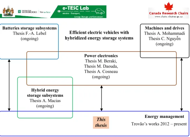
The thesis is also under the Canada Research Chair program in Efficient Electric Vehicles with Hybridized Energy Storage Systems conducted in UdeS [CRC 2017] (Figure 1.11). The research project aims to study the subsystems of EVs including electrical machines [Shah Mohammadi 2018], power electronics [Beraki 2017; Daouda 2018], and batteries and H-ESSs
[LeBel 2018; Pelletier 2018]. To coordinate these subsystems in an efficient EV, there are works on energy management [De Castro 2012; Gomozov 2017; Machado 2016; Trovão 2013b, 2015b, 2017] those the thesis is based on.
The technical context of the thesis is also in the common interest of French and Canadian research programs, under CE2I (Integrated Intelligent Energy Converters) and Mitacs Accelerate, respectively. Within CE2I program, a multi-source hybrid truck is studied as a concept of integrated intelligent transportation. Meanwhile, within Mitacs Accelerate program, the project focuses on multi-machine multi-source vehicles. That context leads to the studied systems of this thesis those are an EV and a hybrid truck supplied by H-ESSs combining Li-ion batteries and SCs.
This section has already discussed the global context of studying EVs and HEVs, the needs of hybridizations, the scientific context of the research networks and programs, and the technical context on the studied systems of the thesis. It has been figured out that energy management plays an essential role in hybridized electrified vehicles. In the next section, a state-of-the-art review on methods for EMSs development will be presented.
This thesis
Batteries storage subsystems
Thesis F.-A. Lebel (ongoing)
Machines and drives
Thesis A. Mohammadi Thesis C. Nguyễn (ongoing) Power electronics Thesis M. Beraki, Thesis M. Daouda, Thesis A. Cosneau (ongoing) Energy management
Efficient electric vehicles with hybridized energy storage systems
Hybrid energy storage subsystems
Thesis A. Macias (ongoing)
Trovão’s works 2012 – present
1.2. State-of-the-art review on energy management strategies
Before addressing the energy management methods, a general description of studied hybrid systems with EMSs could be useful (Figure 1.12). The general system can be considered as a combination of a primary source and a secondary source. The former is the energy source or storage that provides the main long-term energy to guarantee the driving range of the vehicle. For example, in an HEV, the ICE is the primary source, whereas in an EV, the batteries play this role. The secondary source is the ESS that can be frequently charged/discharged during the operations of the vehicles. The role of the secondary source is to support the primary source to achieve energy management objectives. For instance, in HEVs, batteries are secondary source that provide electrical power to help the ICEs to reduce fuel consumption and/or emission. Meanwhile in battery/SC EVs, SCs are the secondary one to extend batteries life-time by compensating high fluctuated power request.
ss2 es2 Sec. S. Prim. S. ss1 es1 Energy conversion Energy coupling econ1 scon1 econ2 scon2 ecoup scoup Trac. ss
Energy management strategy Constraints Objectives = Direct connection Multi-physics energy conversions Mono-physics energy conversions
Prim. S.: Primary source Sec. S.: Secondary source Trac. ss: Traction subsystem
Power input/output Signal
Figure 1.12: EMR-based general description of multi-source vehicles with EMSs. Energy sources and storages can produce and store energy in different physical forms, e.g., ICEs impose mechanical energy whereas batteries exchange electrical energy. To work in a system, they need to be associated with multi-physical energy converters. For example, electrical machines convert electrical energy to mechanical energy and vice versa, so that batteries can work with ICEs in HEVs. Furthermore, to effectively operate multi-source systems, the energy flows should be controlled (by EMSs). The energy conversions should be controllable, such as electrical drives (electric machines, power electronics converters, and their control). The controlled energy flows combine at the energy coupling to supply energy to the traction subsystem or the drivetrain. EMSs are implemented in the strategy block. The EMSs measure and/or estimate the system variables to impose the energy flows references in order to obtain the objectives while satisfying the constraints.
In this study, the development methods are organized based on the traditional classification proposed in [Salmasi 2007]. In this work, a more detailed classification of energy management methods is presented (Figure 1.13).
ENERGY MANAGEMENT Rule-based methods Optimization-based methods Deterministic Artificial intelligence Frequency-based Mode-based Feedback control Fuzzy logic Artificial neural network (ANN) Global optimal Dynamic programming (DP) Pontryagin’s minimum principle (PMP) Other methods Real-time near-optimal Optimal control-based Meta-heuristic optimization Equivalent consumption minimization strategy (ECMS) Model predictive control (MPC) • Filtering-based • Wavelet-based • DP solution-based • Stochastic DP • PMP-based • Linear control • Non-linear control
Figure 1.13: Classification of energy management methods. 1.2.1. Rule-based methods
Rule-based methods are classified into deterministic and artificial intelligent (AI)-based groups. The former ones are explicit rules deduced from user’s knowledge of the systems behaviors. Whereas the rules of the latter ones are based on AI methods to simulate the human behaviors and learning abilities. Rule-based strategies are often easy to be implemented in real-time which
is suitable for real-world applications. However, they are not optimal and dependent on human expertise.
a. Deterministic rule-based methods
Frequency-based methods
H-ESS and HEVs are the combinations of energy sources; in which there are often sources preferable to work at low frequency (LF) and the other ones more suitable for high frequency (HF). Hence, it is straightforward to develop EMS based on frequencies of power references (Figure 1.14). LF power demand corresponds to the steady state driving and HF power demand corresponds to the variations (acceleration and regenerative braking). The methods can be classified as filtering-based and wavelet-based regarding the most common used techniques of frequency separation. ss2 es2 Sec. S. Prim. S. ss1 es1 econ1 scon1 econ2 scon2 ecoup scoup Trac. ss
Knowledges of sources behaviors in term of response frequency
(e.g., fsec. S >> fprim. S)
Frequency processing
(filtering/wavelet/etc.) HF power
demand LF power demand
Strategy fcut-off
Figure 1.14: General description of EMSs with frequency-based methods.
Filtering-based methods
Frequency separation can be realized by using low-pass or high-pass filters (LPFs/HPFs) to generate the power references for energy storage devices. This is a very simple but effective method for energy management.
Two LPFs are used for a fuel-cell/battery/SC energy storage subsystem, in which one is for fuel-cell and one is for batteries power references [Schaltz 2009]. Two EMSs, which are with or without batteries, are investigated. The objective of batteries life-time extension is examined in terms of number of cycles and depth-of-discharge (DoD). Two configurations of fuel-cell/SC and battery/SC H-ESSs are studied in [Tani 2012] using LPFs. The performances of DC bus voltage control, storage devices currents control, and EMS are verified by experiments.
An adaptive mechanism for the time constant of the LPF of battery/SC H-ESS energy management is proposed in [Florescu 2015]. The time constant is adapted regarding the SCs voltage. The time constants of the LPFs can be chosen based on the Ragone plot [Christen 2000] as addressed in [Akli 2009] for flywheel, batteries, and SCs, in [Dépature 2018b] for fuel-cells and SCs, and in [Allègre 2013; Nguyễn 2016] for battery/SC H-ESS.
Not only for energy storage subsystems, filtering-based strategy can be also applied to energy management of HEVs. In [Kim Y. 2014], the so-called frequency-domain power distribution strategy is investigated for hybrid powertrains. The studied system is examined by several hardware-in-the-loop experiments including the so-called battery-in-the-loop and engine-in-the-loop.
Wavelet-based methods
To separate the frequencies of the energy sources, wavelet transformation technique can be used. The Haar wavelet is used in [Zhang 2008] for energy management of a fuel-cell/battery/SC H-ESS. The three-level wavelet-based scheme decomposes the demanded traction power into 3 frequency components for fuel-cells, batteries, and SCs. A similar multi-level decomposition is also applied in [Uzunoglu 2008] for a fuel-cell/SC system. Wavelet transformation is used in cooperation with a nonlinear auto-regressive neural network for a battery/SC military hybrid vehicle in [Ibrahim 2016]. The neural network predicts the requested power for the wavelet transformation to decompose the power frequency.
The advantage of wavelet technique is the localized signal decomposition in both time and frequency domain. This sort of methods requires wavelet transformations which make it more complicated to be implemented in on-board embedded systems in comparison to the filtering-based approach.
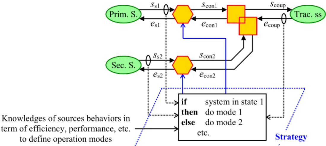
Mode-based methods
This group addresses the mode-based methods which are developed by heuristic approaches. They are normally in a general form like “if the system is in this state then the strategy should be in that mode” (Figure 1.15). Mode-based methods can be considered as the simplest approach to develop EMSs. The strategies can be easily implemented thanks to their intuitive approach. There is, however, almost no systematic methodology to develop them.
Baseline control strategy, which is used in ADVISOR, is applied in [Johnson 2000] for HEVs. Maximal and minimal torque envelopes are defined. The operation of the engine depends on these envelopes and batteries SoC levels. An 8-state mode-based strategy is proposed for energy management of a full-active fuel-cell/battery H-ESS for a tramway [Garcia 2010]. The operation modes are defined based on the batteries SoC and the load power. A similar 7-state EMS is presented in [Hannan 2012] for a multi-source system combining fuel-cells, batteries, and SCs. A series HEV using H-ESS combining batteries and SCs are studied in [Yoo 2008]. The mode-based EMS manages both mechanical and electrical couplings. Hence, the strategy is considered as composition approach even though the voltage and current controls are separated from the EMS. Mode-based strategies are also of interest for managing the operations of batteries and SCs in other applications like smart DC grid [Sechilariu 2013; Yin 2017].
ss2 es2 Sec. S. Prim. S. ss1 es1 econ1 scon1 econ2 scon2 ecoup scoup Trac. ss
Knowledges of sources behaviors in term of efficiency, performance, etc.
to define operation modes
if system in state 1
then do mode 1 else do mode 2
etc. Strategy
Figure 1.15: General description of EMSs with mode-based methods.
Feedback control-based methods
The subject of energy management is dynamical systems. It is therefore reasonable to develop EMSs using automatic control theory (Figure 1.16). The methods can be classified as linear and non-linear control. In which, linear control is often applied with decomposition approach; while non-linear control frequently goes with composition approach.
ss2 es2 Prim. S. ss1 es1 econ1 scon1 econ2 scon2 ecoup scoup Trac. ss Automatic controller (linear/non-linear) + – Feedback (Disturbance) Reference Sec. S. Strategy (Disturbance)
Figure 1.16: General description of EMSs with feedback control-based methods.
Linear control
The linear control scheme is applied for energy management of the H-ESS combining fuel-cells, batteries, and SCs in [Thounthong 2009]. The proportional controllers are employed for SCs and batteries voltage control. The studied systems are well examined by experiments. However,
it could be noted that while the SCs voltage directly relates to their SoC, the batteries voltage does not. Hence, the batteries voltage control loop could be appropriately replaced by their SoC control with the estimation of the batteries SoC from their voltage.
Proportional-integral (PI) controller with anti-windup mechanism is used to control the SCs voltage that is called “compensation loop” for fuel-cell/SC H-ESS in [Azib 2010]. DC bus voltage and SCs current control loops are developed independently with the outer supervisory control of SCs voltage. PI controller for batteries and SCs SoC management are also investigated for a hybrid vehicles in [Wang L. 2011].
In [Nguyễn 2018b], the author proposed a merging control of an H-ESS for EVs. It is developed based on the principle of inversion of EMR. A closed-loop voltage control for SCs has been introduced to couple with the traditional open-loop current control of the batteries. The trade-off between the two different objectives is addressed by a weighting factor.
Non-linear control
In [Thounthong 2010], the DC bus and the SCs voltages are considered in the same framework of non-linear flatness-based control for a fuel-cell/SC system. Similarly, non-linear control is also applied in [Ayad 2010; Benmouna 2018; Hilairet 2013] with the passivity-based control technique.
A fuel-cell/battery/SC H-ESS is considered as a multi-input multi-output (MIMO) system that is controlled by a control Lyapunov function (CLF) in [Rajabzadeh 2016]. Non-linear control with CLF and sliding mode control technique are also investigated by the authors of [Song 2017] for battery/SC EVs. With the similar composition approach, an H-ESS can be treated as a port-controlled Hamiltonian system as in [Dai 2016]. Disturbance rejection for energy management of the system is then developed.
Feedback control-based methods are model-based strategies which can be systematically deduced by using control theory and system dynamical models. They are therefore promising for EMSs development. Nevertheless, it often causes confusions when the low-level (local) controls are mixed with high-level (supervisory) EMSs. The plants can therefore become huge non-linear MIMO systems which make the control laws very complicated. It could be better if the two levels are decomposed regarding their objectives, functions, and dynamics. It is also interesting to note that there is a lack of feedback control-based strategies developed for HEVs energy management. This could be therefore promising to initiate applications of advanced control technique to EMSs of HEVs.
b. Artificial intelligence-based methods
Fuzzy logic-based methods
It is reasonable that fuzzy logic is widely used for EMSs development since it is close to human decision making. It can be stated that fuzzy logic-based EMSs are mode-based strategies but in the language of fuzzy logic. The mode-based approach has been already addressed in the