1
Experimental Study of Energy Management of FC/SC Hybrid System Using
The Passivity Based Control
A. Benmouna1, M. Becherif1, C. Dépature2, L. Boulon2, D. Depernet1
1FCLab, FR CNRS 3539, Femto-ST, UMR CNRS 6174, Bourgogne Franche-Comte University/UTBM,
Belfort Cedex, France
2 Université du Québec à Trois-Rivières, Hydrogen Research Institute, Trois-Rivières, Canada
Abstract — Nowadays, the energy management of the hybrid system is becoming an interesting and the challenging topic for several researchers. The wise choice of the energy management strategy allows not only the best distribution of power between different sources but also reduce system consumption, increase the lifetime of the used sources and ensure the energy demand that involve the autonomy of the electrical vehicle. In this paper, the control and the energy management using the passivity control is adopted to the multiconverters multisources system, in particularly, Fuel Cell/SuperCapacitor (FC/SC) hybrid system. In the proposed system, the FC represents the main source and the SC is used for the transient of power where they can absorb or supply powers peaks. The proposed system is validated by experimental results. The obtained results prove the efficacy and the feasibility of the proposed approach for a real electrical vehicle.
Keywords— Electric vehicle, Fuel cell, Supercapacitor, Multi-source, hybrid system, Passivity Based Control (PBC).
I. INTRODUCTION
The global average temperature of the planet has been rising since the beginning of the industrial era (1880-1899). The greenhouse gases created by the transport sector accelerate this phenomenon. In 50 years, the number of cars will be increased by 160 % [1],[2]. Cleaner means of transport must be proposed. By using hydrogen, Fuel Cell (FC) vehi-cles are a promising solution to reduce greenhouse gases. The FC converts the chemical hydrogen energy into electrical energy to supply an electric traction motor. With a full tank of H2 (generally 5.5 kg of H2 pressurized at 700 bar) [3]),
a driver can expect to travel about 500 km, against 200 km for a regular battery electric (e.g. 2016 Nissan Leaf) car and 1,000 km for a conventional thermal vehicle. Moreover, the hydrogen tank is filled up in a few minutes in station whereas a full regular charge of a battery electric vehicle lasts several hours (In France, 350 bars is the standard hydro-gen pressure for FC car). However, FCVs have to face some issues.
FC systems offers a limited dynamics. Fast power transients can lead to a gas starvation, which can permanently damage the FC [4]. Furthermore, the energy flow of FC systems is unidirectional, which does not allow recovering braking energy [5]. Hybridization of FC with other Energy Storage System (ESS) devices can thus improve the vehicle performances [6]. A battery can be used as a secondary source to handle the power transients, to recover braking energy, to extend its lifetime and to reduce its cost. With their Mirai and Tucson car, Toyota and Hyundai have chosen this technology using Ni-Mh and Li-Poly battery packs, respectively [7]. Hybridization of a FC with SuperCapacitors (SC) as energy/power buffer represents another interesting solution. With its high specific power and power density, SCs can easily assist FC to meet the high power requirements [5],[9]. Further, while a cycle life of 1,000 can be expected for battery [10], SCs can last from 500,000 to 1,000,000 cycles [11]. With its 2002 FCX, Honda has first chosen this technology to supply addition power to its vehicle. The new 2014 FCX clarity use a FC/battery configura-tion. Indeed, in recent years, batteries made significant progress. In addition, batteries are well known to manufacturers, as they are used for their hybrid models (e.g. Toyota Prius). Henceforth, industrial applications are taking advantages of both battery and SC to assist FC vehicles.
Depending on technical and financial specifications, direct or indirect FC/SC/battery configurations are possible [12],[13],[14]. In this paper, an indirect FC/SC configuration is chosen (see Fig.1). The secondary ESS is then the SC, which is lighter, more robust and has a higher power density than batteries. The use of two converters allows managing the sources according to a specific energy management strategy. This can be based on fuel consumption or source
11583-11592. CC BY-NC-ND 4.0 http://dx.doi.org/10.1016/j.ijhydene.2018.03.191
degradations arguments [14], [15].
The control of FC vehicles using SC must take into account the constraints related to this association. First, these sub-systems are strongly coupled. Both sources are indeed connected through a DC bus. For example, the FC or the SC cannot independently meet the requested traction energy and power flows. For that, it is necessary to control and manage the interaction and the coupling between the both sources. Numerous studies have discussed on the control and energy management of FC/SC vehicles using PI controllers [16], [17], flatness control [9] and fuzzy logic control-lers [18]. However, most of these propositions have been evaluated only in simulation. Secondly, all of the vehicle components have nonlinear behaviors [19],[20]. These constraints affect the system stability. In this way, the previ-ously mentioned works well managed the FC/SC system, but did not ensure the stability, especially where saturation occurs [16]. It is well established that nonlinear behaviors affect the system stability [19]. Instability can cause energy losses and potentially damage on the vehicle. To solve this issue, several authors have proposed to use energy-based Lyapunov control theory for the controller design [21], [22], [23], [24], [25], [26]. In [27], the energy management is proposed for FC/SC system in order to minimize the hydrogen consumption and to limit the current fluctuation for FC. The considered energy management is based on Fuzzy logic controller and filter is used to increase the FC lifetime[27]. Furthermore, the genetic algorithm is used to solve the optimization problems for fuzzy energy management strategy [27]. The simulation results showed a good power distribution and the optimization goals were achieved. However, the stability proof is not given, the results is limited on simulation and the considered energy management is complex. Another work on energy management proposed by [28] and is achieved as a two levels control structure. One is based on PI controller and is addressed to the inner control loop for FC/SC currents and DC bus voltage. The second level is based on Equivalent Consumption Minimization Strategy (ECMS) in order to regulate the FC power considering the minimization of the hydrogen consumption. The proposed strategies lack the stability proof and validation on real hybrid system [28]. The authors of [29] have proposed to study the hybrid system composed of FC and SC. The con-sidered energy management strategy combines the optimal control and Marcov chain to predict the required power. Two constraints at extreme driving conditions are taken into account namely the high power and high speed. The obtained simulation results have shown that the importance to add the Marcov model in limitation of the problem of slow FC dynamic response and to maintain the SC state of charge. In [30], the authors have used the combination between PBC and Fuzzy logic strategies to control the FC/SC hybrid system. The PBC technic is used to control the power source however the Fuzzy logic method is employed to estimate the desired SC current according to its state of charge and hydrogen level. In [30], the seventh order state space model is studied and the proposed controller is vali-dated using the simulation. The proposed energy management for FC/SC system in [31] is based on a frequency dis-tribution technic. The authors have implemented the experimental data of FC and SOC of SC parameters to emulate the real behavior of the used sources. A dynamical management of the energy required between FC and SC is achieved while operating the sources at their best operating points. In other hand, the undesired phenomena that degrade the FC performance are avoided [31]. The authors of [32] have focused on IDA-PBC energy management strategy of FC/SC hybrid system. The overall studied model in [32] was of a third order. In this work, five scenarios have been proposed according to the SC SOC, hydrogen consumption and braking mode. The validation of the proposed control has been evaluated in Matlab/Simulink software. In [32],[33], the studied control strategy for FC/SC hybrid system is based on IDA-PBC. The control design has the objective to regulate the FC voltage to track the DC bus voltage and to control the SC charging/discharging. In these studies [32],[33], the control strategy structure is composed on three subsystems, that are: two inner current loop controllers for FC and SC based on PI controllers, where duty cycle parameters are the outputs. The third subsystem is the outer loop based on IDA-PBC to control the DC bus voltage and SC SOC. Another work has been focused on the energy management of FC/SC hybrid power system using the flatness control algorithm [34]. The used method principle is based on knowing the trajectories of the flat output variable to obtain the trajectories of the state and control variable [34]. Among the hybrid power system studied in [35] the FC/SC hybrid system. The authors of [35] have chosen the nonlinear control approach based on Lyapnov theory in order to ensure the regulation of DC bus voltage and tracking the SC current to its reference. The proposed energy control is applied during the steady state phase, transient phase and start up condition.
Table1: Advantages and drawbacks of different control strategies
Method Advantages Drawback Reference
Lyapnov control theory - Asymptotic stability was ensured. - 3rd order state space model.
- Validation only in simulation
- Four inputs are necessary for the control.
Fuzzy logic based on the
differential flatness - The proposed control was vali-dated in simulation and experi-mentation.
- Real time implementation
- Stability proof was missing - Three converters are used, more
expensive.
- The control method is complex.
[18]
Fuzzy logic+low pass filter
controller - Constraints consideration in the sources. - Source lifetime improvement - Real time implementation
- Validation only in simulation. - Stability proof missing.
- Combination of two controllers, so more complex.
[27]
Frequency based
distribu-tion - Real time implementation. - Different load profiles are used. - Increase the lifetime of the sources
- Validation only in simulation - Complex control strategy
(re-quiring of nested loops). [31] Our strategy
IDA-PBC - The whole system is modeled un-der 5 order state space model. - Proof stability is given
- The proposed control is experi-mentally validated.
- Few measures are required for system control (VFC,VDC).
- Despite that the load power profile is changing, the DC voltage is sta-ble and come back each time to its desired reference.
- Simple implementation of the pro-posed control.
- Constraints consideration in the sources is missing but it can be done using an appropriate choice of ISCref (future work).
[this article]
The principal idea of this work is to control the hybrid system composed of FC and SC using the nonlinear Passivity Based Control (PBC) control. The remainder of the paper is organized as follows: The Section 2 presents the problem formulation of this study. In this part, the authors stated the main objective of this study and the interest of Intercon-nection and Damping Assignment-Passivity Based Control (IDA-PBC) strategy. The Section 3 is dedicated to describe in one hand the FC/SC system structure and the other hand the system representation in form of state equation, where the five order system is proposed. In the same Section, the Port Controlled Hamiltonian (PCH) of the whole system is presented and the control laws obtained from IDA-PBC are given. The Sections 4 is devoted to explain the test bench of the system. In the Section 5, the obtained results from the experiment are presented and discussed. The Section 6 is dedicated to the conclusion.
II. PROBLEM FORMULATION
The main objective of this study is the load power control by splitting the power into DC bus voltage control through the DC-DC FC boost converter and the DC-DC current bidirectional SC converter. Furthermore, the SC voltage (con-sequently the state of charge) is controlled to its nominal value (see Fig.1). In this work, the FC ensures the mean load demand in the permanent phase. However, the role of the SC, as an auxiliary source, is to supply the load in the transient phases. The excess power production or the braking phase energy recovery can be stored in the SC. To achieve these goals, the authors propose an effective energy management strategy based on PBC.
structural properties like the total system energy, the damping and the states interconnections [25]. The IDA-PBC method is a powerful nonlinear technique dealing with important system information like the system’s total energy and it is considered as a general way of stabilizing a large class of physical systems [37].
III. HYBRID FC SYSTEM STRUCTURE
In this work, the studied hybrid system is composed of the FC as a primary source, the SC as a storage system and the DC/DC converters, the unidirectional converter is linked to the FC and the bidirectional is connected to the SC. The load is represented by RLE circuit. Furthermore, the proposed structure that allow combining these different sources is the parallel structure (see Fig.1).
Fig.1. FC/SC system structure
The hybrid system is written in form of state space equation by choosing the state space variable as follow: 𝑥 = [𝑥1 , 𝑥2, 𝑥3 , 𝑥4, 𝑥5]𝑇 = [ 𝑖𝐹𝐶, 𝑉𝐷𝐶, 𝑖𝑠𝑐 , 𝑉𝑠𝑐, 𝑖𝐿]𝑇
Therefore, the studied model is a five order system given by: 𝑥̇1= 1 𝐿𝐹𝐶 [𝑉𝐹𝐶−µ1𝑥2] 𝑥̇2 = 1 𝐶𝐷𝐶 [µ1𝑥1− 𝑥5+ µ2𝑥3] 𝑥̇3= 1 𝐿𝑆𝐶 [𝑥4−µ2𝑥2] 𝑥̇4= − 1 𝐶𝑆𝐶 𝑥3 𝑥̇5= 1 𝐿𝐿 [𝑥2−𝑅𝐿𝑥5− 𝐸𝐿] (1)
µ1, µ2 are the modulation ratios of the FC boost converter and the SC control of the buck-boost converter, respectively.
After simple calculations, the equilibrium trajectory are given as:
𝑥̅ = [𝑥̅1, 𝑥̅2, 𝑥̅3 , 𝑥̅4, 𝑥̅5 ]𝑇 = [𝑥̅1, 𝑉𝑑, 𝑥̅3, 𝑉𝑆𝐶𝑑,
𝑉𝑑− 𝐸𝐿 𝑅𝐿
] 𝑇
𝜇̅1= 𝑉𝑓𝑐
𝑥̅2 ; 𝜇̅2= 𝑉𝑆𝐶𝑑
𝑥̅2 (2)
The desired closed loop energy function is given by:
𝐻𝑑= 1 2𝑥̃
𝑇𝑄𝑥̃ (3)
With 𝑥̃ = 𝑥 − 𝑥̅ is defined as the error between the state 𝑥 and its equilibrium value𝑥̅. Moreover, 𝑄 is a diagonal matrix. The model is rewritten using the new state space (error dynamic)
𝑥̃̇1= 1 𝐿𝐹𝐶 [−𝜇1𝑥̃2+ 𝑉𝐹𝐶− 𝜇1𝑥̅2] 𝑥̃̇2 = 1 𝐶𝐷𝐶 [𝜇1𝑥̃1+ 𝜇2𝑥̃3− 𝑥̃5+ 𝜇1𝑥̅1− 𝑥̅5+ 𝜇2𝑥̅3] 𝑥̃̇3= 1 𝐿𝑆𝐶 [−𝜇2𝑥̃2+𝑥̃4− 𝑥̅4− 𝜇2𝑥̅2] 𝑥̃̇4= − 1 𝐶𝑆𝐶 [𝑥̃3− 𝑥̅3] 𝑥̃̇5 = 1 𝐿𝐿 [𝑥̃2− 𝑅𝐿𝑥̃5+𝑥̅2− 𝑅𝐿𝑥̅5− 𝐸𝐿] (4)
The error dynamic equations are expressed using the gradient of the desired energy as follows:
𝑥̃̇ = [𝐽 − 𝑅]∇𝐻𝑑+ 𝜉 (5)
𝐽(𝜇) = − 𝐽𝑇(𝜇) is a skew symmetric matrix defining the interconnection between the state space and R=RT≥0 is a
symmetric positive semi definite matrix defining the damping of the system. With control laws chosen as:
{𝜇 𝜇1= 𝜇̅1
2= 𝜇̅2− 𝑟𝑥̃3
(6)
Where r is a positive design parameter.
The choice of µ1 allows the control of the DC bus voltage despite the variation of the FC voltage (see eq (2)) and the
choice of µ2 allows the control of the current (x3) and the SC voltage to its desired and nominal value (see eq (2)).
The origin of the closed loop system with the control laws with radially unbounded energy function is globally stable. Proof: the system stability in closed loop is given by:
𝑥̃̇ = [𝐽(𝜇) − 𝑅′]∇𝐻𝑑 (7) With 𝑅′ = 𝑑𝑖𝑎𝑔
{
0; 0; 𝑟 𝐿𝑠𝑐2 ; 0; 𝑅𝐿 𝐿𝐿2}
= 𝑅 ′𝑇 ≥ 0The time derivative of the desired energy along the trajectory is:
𝐻
̇
𝑑 = ∇𝐻𝑑𝑇𝑥̃̇
= −∇𝐻𝑑𝑇𝑅′∇𝐻𝑑≤ 0 The Fig.2 gives the bloc scheme of the IDA-PBC principalFig. 2. IDA-PBC principles
itot1 ufc ubus Lfc ifc ifc_ch ufc_ch usc Lsc isc isc_ch usc_ch T its is isc_ch + - rsc Csc
Energy Storage Subsystem Traction Subsystem (TS)
ubus
its
TS equivalent power load
Fig. 3. Studied FC/SCs vehicle architecture IV. REAL-TIME VALIDATION
A. Experimental setup
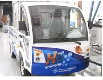
Based on the traction characteristics of the test bench low speed Nemo electric vehicle of the Hydrogen Research Institute (UQTR Canada) (Fig. 4) a reduced scale validation is proposed on an experimental platform From Fig.7, it is
composed of a 500 W Horizon PEMFC (c), a bank of Maxwell SC (f), two 2 kW adjustable self-contained Zahn chop-pers (a), a DC bus capacitor (b) and a 500 W programmable DC load (d) to emulate the traction subsystem (see Fig.7). The programmable DC load is then chosen as a load drive with a power reduction of 60 compared to the full scale studied vehicle. In addition, the regenerative braking phases are not considered because the programmable load only provide positive power. Only mechanical braking are considered for the braking phases. However, a DC bus voltage variation is considered allowing thus to recover the excess power to recharge the SC pack. Voltages and currents are measured with classical LEM transducers and voltage probes (g). No additional numerical filters have been added.
Fig. 4. Nemo electric vehicle
Table 2. Parameters of FC/SC vehicle test bench
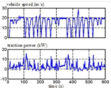
An on-road urban driving cycle has been carried out with the Nemo vehicle at the Université du Québec à Trois-Rivières, on and around campus (Fig.5). The studied driving cycle is composed of a repetitive sequence of constant speed (20 m/s), acceleration and braking phases. This results on a full scale traction power profile (Fig.5). In this section, the on-road power profile is reproduce by the programmable load with a scale reduction of 60 while limiting to positive power demand. The developed control objective is to supply the emulated traction system while distributing the power flow between the FC and the SC.
Components Full-scale FC/SC EV
FC 15-32 V / 500 W
SCs 32 V, 29 F
DC bus capacitor 80 V / 100 mF
Boost choppers 2 kW
current or voltage control
Fig. 5. Full scale Nemo vehicle speed and power from an on road test drive itot1 upac ubus Lpac ipac ihpac usc Lsc isc ihsc uhsc ist is current control
Pload-ref power control
NI PCI-6229 System developed control H2
H2 tank
prog. load
voltage control
Fig. 6. Experimental setup organization
The developed control is build and implemented in a National Instrument NI PCI-6229 controller through LabVIEW software (h). The FC system, the SC system and the programmable load are connected together by mean of three 40 A contactors Kfc, Ksc and Kload, respectively (Fig.6). The management of the contactors allows three operation modes:
1) Mode 1: DC bus initialization. Kfc is closed. Ksc and Kload are open. The FC chopper control the DC bus voltage at
40 V.
2) Mode 2: SC charge. Kfc and Ksc are closed. Kload is open. The FC chopper control the DC bus voltage at 40 V and
the SC chopper control the SC current. The FC then maintain the DC bus voltage and charge the SC to 24 V.
3) Mode 3: Vehicle operation. Kfc, Ksc and Kload are closed. The emulated traction load is connected to the DC bus.
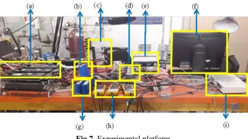
Fig.7. Experimental platform
(a) Converters; (b) DC bus; (c) FC; (d) contactors; (e) programmable load; (f) control unit; (g) SC module; (h) sen-sors; (i) acquisition system;
V. EXPERIMENTAL RESULTS AND DISCUSSION
(a) (b)
Fig. 8. Experimental results of (a) the SC current and its reference; (b) zoom on a part of the curve (a)
Fig.8 (a) presents the SC current and its reference. It can be seen that the SC current tracks exactly the reference with no overshoots and this at all time. This is clearly demonstrated in the Fig.8 (b) that corresponds to the zoomed region from Fig.8(a). It also should be mentioned that the SC is used only to absorb or supply the transient power.
Fig. 9. Experimental results of the SC voltage Vsc and the desired voltage of SC 𝑉𝑆𝐶𝑑
Fig.9 shows the SC voltage and the desired voltage of SC. The SC voltage tracks its reference quite good, the deviations from the reference are due to the contribution of the SC. Indeed, when the SC contribute to power the load (current control) they are discharged and consequently the voltage decreases. Also, if there is an excess of power, the can absorb the negative current and consequently they are recharged and their voltage increase. This reflect exactly the imposed scenario for the SC.
(a)
(b)
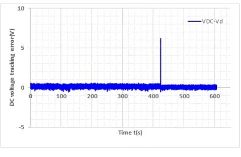
Fig. 10. (a) DC bus voltage VDC and the desired voltage Vd , (b) voltage control error
Fig.10 (a) presents the response of the system to the desired DC bus voltage step change. The value of the DC bus voltage 42 V corresponds to the new standard voltage for automobile system (see [38]). The DC voltage follows exactly its reference at all time. At 424s, a change in the desired voltage is made from 42 V to 36 V and the DC bus voltage tracks rapidly with almost no overshoot the desired reference illustrating the performance of the IDA-PBC controller. Fig.10 (b) shows the error of DC bus voltage that tends to zero.
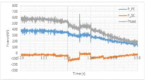
Fig. 11. Experimental results for powers
Fig.11 represents the load power demand, the FC power and SC power. It can be seen that the FC ensure the majority of the load demand. However, the SC supplies and absorbs the transient power peaks. It is also clearly shown that the load power is the sum of the SC and FC power at each moment. Fig.11 demonstrates also the discharge of the SC that corresponds to the negative SC power for example at t = 120s to 130s, in this case the FC charge the SC (Fig.12). Furthermore, this figure shows the complementary role between FC and SC to supply the load and this corresponds to the period between 370s to 375s (see Fig.13) .This figure is important and reflects exactly the proposed scenario and it illustrates the advantages of the power control between FC, SC and the load.
Fig. 12. Experimental results for powers showing the negative power of SC
Fig.13 shows the complementary role between FC and SC
Fig. 13. Experimental results for powers showing the complementary role between FC and SC VI. CONCLUSION
This paper presents an experimental study on the energy management of a DC hybrid sources system composed of FC/SC. In this system, the FC is used to supply the main load demand at permanent regime and the SC, as auxiliary source, is used in the transient phases. The energy management strategy used in this work is the nonlinear control called IDA-PBC. A mathematical model of the hybrid system is given and the stability proof is presented. Thereafter, the IDA-PBC control is used to intelligently govern the distribution of power between the sources and the load. The ex-perimental results obtained show the effectiveness of the proposed control and this by tracing the plotted curves.
Table 3. Parameters definition
Parameters Definition 𝐿𝐹𝐶 FC inductance 𝑉𝐹𝐶 FC voltage
𝑉𝑑 Desired DC bus voltage 𝐶𝐷𝐶 Converter capacity
ACKNOWLEDGMENT:
The authors gratefully acknowledge the Hydrogen Research Institute (IRH), Université du Québec à Trois-Rivières, CANADA, where the practical work has been carried.
REFERENCES
[1] M. Sorrentino, G. Rizzo, and L. Sorrentino,“A study aimed at assessing the potential impact of vehicle electrification on grid infrastructure and road-traffic green house emissions” , Appl. Energy, vol. 120, pp. 31– 40, 2014.
[2] C. Chan, Y. S. Wong, A. Bouscayrol, and K. Chen, “Powering Sustainable Mobility: Roadmaps of Electric, Hybrid and Fuel Cell Vehicles” , Proc. IEEE, vol. 97, no. 4, pp. 603–607, 2009.
[3] D. J. Durbin and C. Malardier-Jugroot, “Review of hydrogen storage techniques for on board vehicle applications” , Int. J. Hydrogen Energy, vol. 38, no. 34, p. 14595‑ 14617, 2013.
[4] X. G. Yang, Q. Ye, and P. Cheng, “Hydrogen pumping effect induced by fuel starvation in a single cell of a PEM fuel cell stack at galvanostatic operation” , Int. J. Hydrogen Energy, vol. 37, no. 19, p. 14439‑ 14453, 2012.
[5] A. Khaligh, S. Member, and Z. Li, “Battery , Ultracapacitor , Fuel Cell , and Hybrid Energy Storage Systems for Electric , Hybrid Electric , Fuel Cell , and Plug-In Hybrid Electric Vehicles : State of the Art” , vol. 59, no. 6, pp. 2806–2814, 2010.
[6] A. Benmouna, M. Becherif, D. Depernet, and M. A. Ebrahim, “Novel Energy Management Technique for Hybrid Electric Vehicle via Interconnection and Damping Assignment Passivity Based Control” , Renew.
Energy, vol. 119, pp. 116–128, 2018.
[7] B. C. Roberto, Alvarez Fernandez, Fernando and naki V. Martınez, “A new approach to battery powered electric vehicles : A hydrogen fuel-cell-based range extender system” , Int. J. Hydrogen Energy, vol. 1, no. 41, pp. 0–11, 2016.
[8] A. K. and L. Zhihao, “Battery, ultracapacitor, fuel cell, and hybrid energy storage systems for electric, hybrid electric, fuel cell, and plug-in hybrid electric vehicles: State of the art” , IEEE Trans. Veh. Technol, vol. 59, no. 6, pp. 2806–2814, 2010.
[9] A. Payman, S. Pierfederici, S. Meibody-Tabar, and B. Davat, “An adapted control strategy to minimize DC-bus capacitors of a parallel fuel cell/ultracapacitor hy-brid system”, IEEE Trans. Power Ele, vol. 26, no. 12, pp. 3843–3852, 2009.
[10] X. Han, M. Ouyang, L. Lu, and J. Li, “A comparative study of commercial lithium ion battery cycle life in electric vehicle: Capacity loss estimation”, J. Power Sources, vol. 268, pp. 658–669, 2014.
[11] D. B. Murray and J. G. Hayes, “Cycle testing of supercapacitors for long-life ro-bust applications” , IEEE Trans.
Power. Ele, vol. 30, no. 5, pp. 2505–2516, 2015.
[12] W. Billy, M. A. Parkes, V. Yufit, L. De Benedetti, S.Veismann, C. Wirsching, F.Vesper, R. F. Martinez-Botas, A. J. Marquis, G. J. Offer, N. P. Brandon, “Design and testing of a 9.5 kWe proton exchange membrane fuel cell – supercapacitor passive hybrid system”, Int. J. Hydrog. Energy, vol. 39, no. 15, pp. 7885–7896, 2014.
𝐿𝑆𝐶 SC inductance 𝐼𝑆𝐶 SC current 𝐼𝑆𝐶 𝑟𝑒𝑓 SC current reference 𝑉𝑆𝐶𝑑 SC voltage desired 𝐿𝐿 load inductance 𝐸𝐿 f.e.m of load 𝑅𝐿 resistance of load 𝑟 damping parameter 𝑃𝐹𝐶 FC power 𝑃𝑆𝐶 SC power 𝑃𝑙𝑜𝑎𝑑 load power
[13] P. Thounthong, V. Chunkag, P. Sethakul, B. Davat, and M. Hinaje, “Comparative study of fuel-cell vehicle hybridization with battery or supercapacitor storage device”, IEEE Trans. Veh. Technol., vol. 58, no. 8, p. 3892‑ 3904, 2009.
[14] E. Tazelaar, B. Veenhuizen, J. Jagerman, and T. Faasen, “Energy management strategies for fuel cell hybrid vehicles; an overview”, EVS27, Barcelona, Spain, 2013.
[15] C. Dépature et al., “Energy management of a fuel cell/battery vehicle”, IEEE VPP Conf. Hangzhou, China, 2016.
[16] H. Aouzellag, K. Ghedamsi, and D. Aouzellag, “Energy management and fault tolerant control strategies for fuel cell/ultra-capacitor hybrid elec-tric vehicles to enhance autonomy, efficiency and life time of the fuel cell system”, Int. J. Hydrogen Energy, vol. 40, no. 22, p. 7204‑ 7213, 2015.
[17] H. Hemi, J. Ghouili, and A. Cheriti, “Combination of Markov chain and optimal con-trol solved by Pontryagin’s minimum principle for a fuel cell/supercapacitor vehicle”, Energy Convers. Manag., vol. 91, p. 387‑ 393, 2015. [18] P. Thounthong, L. Piegari, S. Pierfederici, and B. Davat, “Nonlinear intelligent DC grid stabilization for fuel cell vehicle applications with a supercapaci-tor storage device”, Int. J. Electr. Power Ener-gy Syst., vol. 64, p. 723‑ 733, 2015.
[19] J. Jia, Q. Li, Y. Wang, Y. T. Cham, and M. Han, “Modeling and Dynamic Characteristic Simulation of a Proton Exchange Membrane Fuel Cell” , IEEE Trans. Ener. Conv, vol. 24, no. 1, pp. 283–291, 2009.
[20] A. . Alanis, E. N. Sanchez, and A. . Loukianov, “Real-time Discrete Backstepping Neural Control for Induction Motors” , IEEE Trans. Control Syst. Tech, vol. 19, no. 2, pp. 359–366, 2010.
[21] H. El Fadil, F. Giri, S. Member, J. M. Guerrero, and S. Member, “Modeling and Nonlinear Control of a Fuel Cell / Supercapacitor Hybrid Energy Storage System for Electric Vehicles”, vol. 63, no. 7, pp. 3011–3018, 2014.
[22] M. Rajabzadeh, S. Mohammad, T. Bathaee, and Aliakbar Golkar, “Dynamic modeling and nonlinear control of fuel cell vehicles with differents hybrid power sources”, Int. J. Hydrogen Energy, vol. 41, no. 30, pp. 3185– 3198, 2016.
[23] C. Dépature, W. Lhomme, P. Sicard, A. Bouscayrol, and L. Boulon, “Real-time Backstepping control for fuel cell vehicle using supercapacitors” , IEEE Trans. Veh. Technol., no. 99, 2017.
[24] O. Kraa, H. Ghodbane, R.Saadi, M.Y.Ayad, M. Becherif, A. Aboubou and M. Bahri, “Energy Management of Fuel Cell/ Supercapacitor Hybrid Source Based on linear and sliding mode control” , Energy Procedia, vol. 74, pp. 1258–1264, 2015.
[25] M. Y. Ayad, M. Becherif, A. Henni, A. Aboubou, M. Wack, and S. Laghrouche, “Passivity-Based Control applied to DC hybrid power source using fuel cell and supercapacitors”, Energy Convers. Manag., vol. 51, no. 7, pp. 1468–1475, 2010.
[26] M. Mohammedi, O. Kraa, M. Becherif, A. Aboubou, M. Y. Ayad, and M. Bahri, “Fuzzy logic and passivity-based controller applied to electric vehicle using fuel cell and supercapacitors hybrid source” , Energy Procedia, vol. 50, pp. 619–626, 2014.
[27] R. Zhang and J. Tao, “GA based fuzzy energy management system for FC / SC powered HEV considering H 2 consumption and load variation” , vol. 6706, no. c, 2017.
[28] I. E. Aiteur, C. Vlad, and E. Godoy, “Energy management and control of a fuel cell / supercapacitor multi-source system for electric vehicles” , pp. 797–802, 2015.
[29] H. Hemi, J. Ghouili, and A. Cheriti, “Combination of Markov chain and optimal control solved by Pontryagin’s Minimum Principle for a fuel cell / supercapacitor vehicle”, Energy Convers. Manag., vol. 91, pp. 387–393, 2015.
[30] M. Mohammedi, M. Becherif, A. Aboubou, O. Kraa, M. Y. Ayad, and M. Bahri, “Fuzzy Logic and Passivity Based Control applied to Hybrid DC Power Source using Fuel Cell and Battery” , Proc. 4th Int. Conf. Syst.
Control. Sousse, Tunis. April 28-30, 2015, pp. 510–515, 2015.
[31] C. Sandoval, V. M. Alvarado, J. Carmona, G. Lopez Lopez, and J. F. Gomez-Aguilar, “Energy management control strategy to improve the FC / SC dynamic behavior on hybrid electric vehicles : A frequency based distribution” , Renew. Energy J., vol. 105, pp. 1–29, 2016.
[32] A. Behdani and M. R. Naseh, “Power management and nonlinear control of a fuel cell–supercapacitor hybrid automotive vehicle with working condition algorithm”, Int. J. Hydrogen Energy, vol. 2, 2017.
[33] S. Mane, F. Kazi, and N. . Singh, “Fuel Cell and Ultra-Capacitor Based Hybrid Energy”, Int. Conf. Ind. Instrum.
[34] M. Hilairet, O. Bethoux, T. AZib, and R. TAlj, “Interconnection and Damping Assignment Passivity-Based Control of a Fuel Cell System” , IEEE Int. Symp. Ind. Electron., pp. 219–224, 2010.
[35] B. M. Saadi Ramzi, Benaouadj M, Kraa O, Becherif Mohamed, Ayad Mohamed Yacine, Aboubou A and Haddi Ali, “Energy management of fuel cell/ supercapacitor hybrid power sources based on the flatness control” , Int.
Conf. Power Eng. Energy Electr. Drives, no. May, pp. 128–133, 2013.
[36] M. Rajabzadeh, S. Mohammad, and T. Bathaee, “ScienceDirect Dynamic modeling and nonlinear control of fuel cell vehicles with different hybrid power sources” , Int. J. Hydrogen Energy, vol. 41, no. 4, pp. 3185–3198, 2016.
[37] M. Becherif and E. Mendes, “Stability and robustness of disturbed-port controlled Hamiltonian systems with dissipation”, in World Congress, Jul 2005, Prague, Czech Republic.
[38] P. Thounthong, S. Raël, and B. Davat, “Energy management of fuel cell / battery / supercapacitor hybrid power source for vehicle applications”, J. Power Sources, vol. 193, pp. 376–385, 2009.