Science Arts & Métiers (SAM)
is an open access repository that collects the work of Arts et Métiers Institute of Technology researchers and makes it freely available over the web where possible.
This is an author-deposited version published in: https://sam.ensam.eu Handle ID: .http://hdl.handle.net/10985/9804
To cite this version :
Ruding LOU, Franca GIANNINI, Jean-Philippe PERNOT, Alexei MIKCHEVITECH, Philippe VERON, Bianca FALCIDIENO, Raphael MARC - Direct modification of FE meshes preserving group information In: Tools and Methods for Competitive Engineering (TMCE'10), Italie, 2010 -Tools and Methods for Competitive Engineering (TMCE'10) - 2010
Proceedings of the TMCE 2010, April 12–16, 2010, Ancona, Italy, Edited by I. Horváth, F. Mandorli and Z. Rusák
Organizing Committee of TMCE 2010, ISBN ----
1
DIRECT MODIFICATION OF FE MESHES PRESERVING GROUP INFORMATION
Ruding LOU
Arts et Métiers ParisTech, France LSIS – UMR CNRS 6168, France
[email protected] Franca Giannini Bianca Falcidieno CNR-IMATI.Ge, Italy {franca.giannini, bianca.falcidieno}@ge.imati.cnr.it Jean-Philippe Pernot Philippe Véron
Arts et Métiers ParisTech, France LSIS – UMR CNRS 6168, France {jean-philippe.pernot, philippe.veron}@ensam.fr
Alexei Mikchevitch Raphaël Marc
Electricité de France Group
Research and Development Direction, France {alexei.mikchevitch, raphael.marc}@edf.fr
ABSTRACT
Nowadays, the mainstream methodology for product behavior analysis and improvement relies on the fol-lowing steps: 1) conceptual solution proposal and CAD prototyping, 2) mesh model creation for Finite Element (FE) analysis, 3) preparation of complex mesh model as specification of semantic information for particular behavior study, 4) advanced FE simu-lation, 5) result analysis and optimization loops. The semantics relative to the simulation model are often associated to mesh entities through the use of so-called mesh groups. During the optimization phase, geometric modifications are generally performed on the CAD model. This requires a complete updating of the FE mesh model repeating all the above listed FE mesh preparation (re-creation of all the groups). In the present paper, we propose a new framework for CAD-less FE analysis. It comes to apply shape modi-fication operators directly to the FE mesh while ex-ploiting and maintaining the available FE semantic information. As a result, multiple steeps of the design process loop, as CAD and mesh model generation, mesh group creation, are avoided. In this paper, we focus on two 3D mesh modification operators: the planar cracking and the drilling.
KEYWORDS
Finite Element analysis, mesh, group, semantics, de-formation, crack, hole.
1. INTRODUCTION
Numerical behavior simulation is fundamental for new solution assessment in various engineering ac-tivities: this allows avoiding physical validation tests. Numerical simulations are generally used during the product development, maintenance or lifecycle prob-lem analysis, and new solution prototyping improv-ing its physical behavior. Such activities are fre-quently submitted to various constraints crucial from the production point of view. For example, in the maintenance/lifecycle problem analysis context, the main constraints remain with the time and cost of the production process stops. Therefore, it is important to be able to provide fast solutions improving produc-tion machinery characteristics as well as satisfying different safety criteria. For example, in the field of power production, it is critical to identify the prob-lem source and to provide the appropriate solution in the shortest time. Thus, experts must have appropri-ate numerical tools helping to rapidly evaluappropri-ate vari-ous alternative solutions.
Unfortunately, the existing classical methodology for product behavior analysis and solution assessment does not answer to these needs. Today, most of the product behavior analyses rely on the following steps: conceptual solution proposal and its modeling using Computer-Aided Design (CAD) tools, meshing
and preparation of complex mesh models for specific behavior studies, Finite Element (FE) simulation, result evaluation and optimization loops. During the optimization phase, geometric modifications are re-quired and generally performed on the CAD models, thus requiring a re-generation of the FE mesh models corresponding to the new solution. This is done by repeating all the preparation steps necessary for ad-vanced FE Analysis (FEA), i.e. shape adaptation on the CAD level, complex and not totally automatic re-meshing of CAD models (e.g. generation of free/mapped meshes, creation of sub-meshes having different topologies, a priori adaptive mesh, creation of doubles entities, etc.), re-creation of FE entity groups, re-assignment of the semantic information (e.g. Boundary Conditions or BCs, material laws, geometric/mechanical characteristics, etc.).
It is clear that this process is time consuming and therefore inappropriate for fast maintenance analysis. Moreover, in this context, the CAD data are frequent-ly not available or not fulfrequent-ly corresponding to the real configuration. Sometimes, data necessary for FE simulation can be obtained though scanning tech-niques. Thus, the creation of the corresponding CAD models would lead to an additional waste of time and should then be avoided as much as possible.
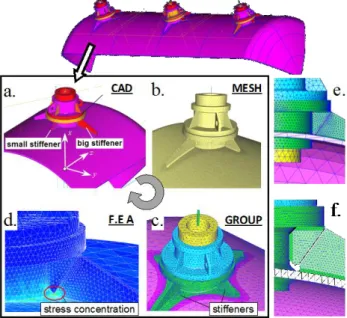
Figure 1 Mainstream methodology for product behavior
analysis and optimization (courtesy EDF-R&D)
Figure 1 illustrates an example of a complex simula-tion the EDF engineers have to deal with. Starting from a real configuration of a caisson in which a structural modification has to be performed to im-prove its mechanical behavior, a new solution
proto-typing method would include classically the follow-ing steps:
1) creation of the complex CAD model (Figure 1.a), which did not exist, corresponding to a part to be repaired;
2) creation of the mesh model containing 1D, 2D and 3D elements and taking into account different aspects such as mesh quality criteria, mechanical modeling hypotheses for particular FE analysis (Figure 1.b);
3) creation of mesh entity groups on which different FE semantics will be defined (Figure 1.c). Here, 30 mesh entity groups have been created to sup-port semantic data. There exists two ways to cre-ate them: either semi-manually by selecting a set of mesh entities and using different criteria or more automatically by selecting the CAD groups of the initial CAD model. This step requires great skill and is time-consuming;
4) FE analysis (Figure 1.d) based on the modeling hypotheses and FE simulation semantics associat-ed to the mesh groups definassociat-ed in the previous step (3);
5) tuning/validation of the FE model through the comparison of experimental and simulation re-sults;
6) result analysis, modeling optimization, proposal of solutions improving the mechanical behavior of the structure, etc. According to the simulation re-sults, and based on the engineer knowledge, the CAD model can de modified in order to prototype the proposed solution. Here, it involves cracking (Figure 1.e), cutting and drilling the stiffener (Figure 1.f). All the above steps from (1) to (4) are then repeated to validate new simulation hy-pothesis and the proposed solution.
It seems quite clear that the return to the CAD model is not the most efficient method to implement a local structural modification. This is especially true when the model contains numerous mesh groups for asso-ciating a lot of semantic data required for mechanical modeling. For example, some EDF models can con-tain up to 500 mesh groups dedicated to the FE anal-ysis (e.g. BCs, link relations, different behavior laws, geometric parameters, mechanical modeling of spe-cific phenomena) as well as particular post-processing data. Unfortunately, current commercial CAD systems do not make it possible to automatize the process of direct complex mesh creation and
DIRECT MODIFICATION OF FE MESHES PRESERVING GROUP INFORMATION
3
modification while preserving such semantic data association. As a consequence, the prototyp-ing/evaluation of structural modifications, even small local changes, requires expensive complete updating of the simulation model that is critical for fast stud-ies.
In order to overcome these limits, we propose a fast prototyping framework working directly at the level of FE mesh enriched by simulation semantics of ge-ometrical nature (mesh groups). This method corre-sponds to a CAD-less approach allowing the engi-neer to directly operate on the meshes containing a great number of semantic data already validated with respect to the real counterpart behavior. More pre-cisely, in the present paper, different mesh modifica-tion operators are proposed. They work directly on the enriched FE mesh models and allow maintaining and propagating the existing semantic information necessary for FE analysis (e.g. BCs, material attrib-utes, etc. associated to the mesh model via groups of FE entities of different topological dimension, i.e. nodes, edges, faces and/or tetrahedrons). The modifi-cations are driven by a deformation engine that takes into account constraints arising from the geometry of the operators as well as the geometry of the bounda-ries of the FE groups. Section 2 recalls the philoso-phy of our multi-layered approach. The geometric operators are introduced in section 3 and additional constraints coming from the use of groups’ bounda-ries are discussed in section 4.
2. A MULTILAYERED APPROACH
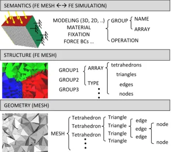
As illustrated in the previous section, FE analysis requires various data/parameters. This information can be classified according to several levels (Figure 2). The geometric data can be considered as the low-est level of information required for FEA. This type of data often describes the shape of the structure to be simulated: it comes to meshed structure. The shape has to be conform to the real geometry of the structure to guarantee an accurate simulation.
At the highest level, FE models include different
se-mantic for modeling the physical behavior of the
structure: material properties, BCs, interaction with a fluid, etc. For example, in order to characterize the material properties, we use Young’s modulus, Pois-son’s ratio, and material laws. The modeling ideali-zation needs other parameters, for example, a thick-ness for a thin structure described as a shell. BCs cor-respond to physical loads of different nature like pressure, concentrated forces, imposed
displace-ments, relationships to simulate a fracture phenome-non or to handle a contact problem, etc.
MODELING (3D, 2D, ..) MATERIAL FIXATION FORCE BCs … MESH GEOMETRY (MESH) Tetrahedron Tetrahedron Tetrahedron Triangle Triangle Triangle edge edge edge Triangle node node GROUP1 ARRAY TYPE GROUP2 GROUP3 tetrahedrons STRUCTURE (FE MESH)
SEMANTICS (FE MESH FE SIMULATION) GROUP OPERATION NAME triangles edges nodes ARRAY
Figure 2 Three levels of information explored on a FE
model.
To be able to relate such semantic data with the dis-cretized geometry, an intermediate layer is needed (Figure 2). This so-called structural level maintains the groups (sets) of FE entities (0-3D dimension ele-ments) and allows associating the semantic data to the lower geometric level (e.g. nodes, edges, faces and tetrahedrons in the case of tetrahedron mesh model). For example, a group of tetrahedrons repre-senting a part of a 3D model can be used to specify a particular material law in order to simulate locally a plastic behavior of the structure. A group of triangles can be used to apply the pressure to the structure. A group of edges may idealize a beam-like-shape part. A group of nodes can be used to fix a part of the structure or to describe displacement relations of dif-ferent nature.
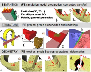
Therefore, during the direct manipulation of FE mesh models containing different structure/semantic data, the mesh modification operators should correctly maintain and update not only the geometry but also all data associated with a given mesh model. Moreo-ver, the associated semantics constrain the FE mesh modification. Thus, effective modification operators should be able to take into account the presented tri-plet level information (Figure 3).
At the lowest level, the “geometric” one, the pro-posed mesh operators directly act on the mesh (e.g. position of the nodes, connections between elements, topology) to perform shape modifications. At the middle level, i.e. the “structure” one, the mesh
opera-tors handle the groups of FE elements of any topolo-gy. On this level, the operators mainly have to pre-serve the group definition during the geometric mod-ification. In order to achieve this, the mesh operators detect the key elements of the FE groups to constrain the geometric modification process and so, to restore the group definition after mesh modification. Simi-larly, on the highest “semantics” level, semantics data has to be handled by mesh operators. Semantic data are both used to set the geometric constraints for mesh modification operators and to specify/update accurately the FE groups.
The aim of the proposed operators is to update cor-rectly all groups in modification zone.
Figure 3 Overview of CAD-less design operators
interact-ing with three levels of FE mesh data
2.1. Different mesh modifications
Mesh modification operators handling 2D/3D FE mesh models can be classified into 3 categories: ma-terial addition, mama-terial subtraction and mama-terial inci-sion operators. Material addition corresponds to mesh merging. Figure 3 presents some examples of 3D mesh modification problem. The Figure 3.a cor-responds to the original mesh M1 before any modifi-cation. The Figure 3.b shows the result of merging operation: a 3D mesh M2 is fused with the mesh M1. The Figure 3.c illustrates the creation of a fillet on a sharp edge. Here, the cylinder-like shape is obtained by deformation around an initially sharp edge. The Figure 3.d shows two consecutive material subtrac-tions: creation of an incision of width L and drilling of a through hole of radius R.
2.2. Proposal of group treatment
We exploit Groups of mesh entities (or FE mesh groups) used to associate FE semantic information to the FE mesh model. FE groups can be used by differ-ent FE solvers. For example, the Code_ASTER®, FE solver developed and distributed by EDF R&D, uses currently mesh groups in order to simplify advanced FEA. The “structure” level shown in Figure 3 pro-vides some industrial examples of mesh groups use-ful for FEA and specific post-processing (courtesy the EDF Group). The Figure 3.e shows a model on which three colored groups of tetrahedrons are de-fined to associate easily different materials to three components of the given structure. In the zone of contact between the pinkish rod and one of the two blue beams (double nodes are located in this area), there are two other tetrahedron groups (Figure 3.f) useful for particular post-processing of FEA results. Overlapping 3D groups illustrated on the Figure 3.e and the Figure 3.f should be correctly managed dur-ing the mesh modification to preserve or propagate the related semantic data. To handle this problem, we propose to decompose groups in non-overlapping groups called “Elementary Groups” (Figure 3.g). The Figure 3.h shows a node group useful for describing a contact problem. The management of overlapping groups of different dimensions is not detailed here (see [2] for more information).
2.3. Proposal of mesh operators
Performing shape modifications on meshes may re-quire substituting some elements of the original FE mesh with new ones to guarantee a better quality of the resulting mesh that is a key aspect for FEA. Mod-ifying mesh elements is generally meaningless from visualization point of view, but it may be not in case of updated FE meshes validated from experience or when some of FE elements support mechanical high-level semantics (Figure 3.i, 3.j and 3.k). Thus, in or-der to maintain and propagate required semantic data, it is necessary to maintain and exploit group infor-mation. The associated physical semantics can be also used for defining constraints during the local re-meshing or mesh deformation of the FE mesh model. Based on these considerations, we have developed different mesh modification operators working on the three layers both on 2D and 3D FE meshes. In par-ticular, in this paper we focus on the crack and hole insertion problem.
DIRECT MODIFICATION OF FE MESHES PRESERVING GROUP INFORMATION
5
2.4. Related work
Bremberg and Dhondt [9] propose an approach for crack insertion into the mesh by creating a blending between the surface mesh of the crack profile and the mesh of the cracked volume. The blending needs re-meshing process for intersection between crack pro-file surface mesh and surface mesh from the hull of the cracked volume mesh, which is for ensuring the shape of the modeled damaged structure. The last is necessary for making two sub-parts in the “cracked” mesh with respect to the crack profile. This approach requires the modeling of the crack as a mesh feature. The main disadvantage of this method is that re-meshing process could be difficult.
Numerical crack introducing and propagation schemes were augmented in an elegant manner with a X-FEM (eXtended Finite Element) method [4,5,6]. The use of special enrichment functions as well as a discontinuous functions along the sides of the crack allows one to achieve “virtually” a complete crack analysis (on mechanical computation level only using so-called “level sets”) without any geometric mesh modification [3]. These works aim at predicting crack behavior on the mesh without using CAD model. However, the application of this method could be difficult in the case of geometrically com-plex cracks having no regular shape (because it is difficult to describe such a crack feature).
In [7,8], the insertion of crack into a mesh model is based on splitting of mesh elements. The direct split of elements could be a very fast process that is cru-cial for real-time visualization of cracking process. Whereas, from the FEA point of view, the resulting mesh is not appropriate because the split elements could have bad quality. The use of Boolean intersec-tion and cut operaintersec-tions between the original model and crack masks have been presented in [10].
Nienhuys and al. [11] describe a cutting algorithm continuously deforming tetrahedrons so that the cut-ting trajectory aligns with the tetrahedron face or edge. This method reduces the need to introduce new nodes but can produce degenerate tetrahedrons. The approach proposed in [12] allows multiple con-secutive incisions of tetrahedrons in the crack zone. Tetrahedron maintains its state information including the number and position of cuts. Multiple cuts are merged, and the affected tetrahedrons are subdivided along the cut plane when a portion of the mesh is completely severed from the rest.
In [16][17][18], a cutting mesh approach is proposed and split directly the elements in order to follow the cutting trajectory. However, the mesh quality is not acceptable for FE analysis.
The cutting operators proposed by [14] and [15] take care about the mesh quality but the cutting profile on the mesh does not perfectly match the cutting tool. In [19], Boolean operations are performed on volume mesh by doing intersection of boundary meshes and completely re-filling tetrahedra. This is not admissi-ble for the case that the tuned FE mesh can be only modified locally.
In [20], a cutting simulation with a mesh of tool and a mesh of operated model is presented. The intersec-tion points between the two interactive meshes are inserted so that the mesh elements are split directly and removed. The cut tool should be meshed and the quality of the result mesh is not enough good for the FE simulation.
In this paper, we present deformation-based cracking and cutting/drilling operations applied to FE mesh while taking into account the presence of mesh groups. Different constraints are created during the mesh deformation in order to preserve the shape of the model as well as the shape of the groups. The next sections are organized as follows: section 3 pre-sents the mesh cracking and cutting operators; sec-tion 4 discusses how to handle the mesh groups dur-ing the geometry modification operation. Section 5 shows some results on industrial models.
3. GEOMETRY OPERATION
3.1. Planar crack operator
Cracks are usually idealized as having no volume. The surfaces representing the two sides are distinct but coincident so that nodes on opposite sides of crack faces should have identical coordinates. So, we can speak about double mesh entities (double nodes and face elements), and the model corresponds to a non-manifold mesh. We present a planar crack opera-tor only. This crack is supposed closed at the initial instant to=0.
It can be mentioned that the duplication of nodes and face elements into a volume correspond geometrical-ly to the introduction of the contact zone. Thus, the crack operator discussed in this section can be used to handle the contact problem in the case of planar surfaces in contact.
Our approach is mainly based on three steps: crack interface identification (section 3.1.1), mesh defor-mation on the level of crack interface (section 3.1.2) and duplication of nodes and faces (section 3.1.3). The crack interface is a set of triangles in case of 3D mesh or a set of edges for 2D mesh. It corresponds to the boundary of the tetrahedrons/triangles lying com-pletely in one side with respect to the crack plane and that have to be deformed to respect this plane. The nodes relative to the interface elements are forced to move onto the crack plane. In order to avoid degen-erated triangles/tetrahedrons, some elements not di-rectly in contact with the crack plane are also moved. The deformation process is based on the one present-ed in [1]. Linear and non-linear constraints requirpresent-ed for local mesh deformation can be specified, and the minimization of a quadratic objective function based on a simple mechanical spring/bar-like model pro-vides the final solution in term of local deformation (it comes to mesh relaxation). Indeed, a bar network is created and coupled to the edges of the 2D/3D mesh. Each bar can be seen as a spring with a null initial length and a stiffness. Finally, the crack inter-face is created by duplicating nodes and inter-faces on the two sides of crack.
These steps are detailed in the following subsections. For sake of clarity, it is supposed that the planar crack affects the entire structure, and that its plane is infinite. In case the crack solely applies locally, addi-tional checks are performed to detect the interface elements really lying in the crack area.
3.1.1. Crack Interface identification
This first step separates all the mesh nodes into two sets (N1, N2) according to their position with respect to the two half-spaces (P,N) defined by the crack plane.
In the case of 3D mesh, a set T1 gathers together the tetrahedra having their 4 nodes belonging to the half-space P, respectively T2 for tetrahedrons having at least one node in the half-space N. Analogously, for 2D mesh, the set T1 gathers together triangles whose 3 nodes belong to the half-space P, and respectively
T2 for triangles defined by at least one node
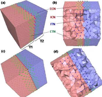
belong-ing to the half-space N. The Figure 5.a shows a 3D mesh and the identified sets T1 and T2 when apply-ing a planar crack.
Now, the Crack Interface (CI) has to be identified. For 3D mesh, the CI is defined as a set of triangles f which are shared by one tetrahedron ti in T1 and one
tetrahedron tj in T2. Analogously, in the case of 2D
mesh, the CI is a set of edges e which are shared by one triangle fi in T1 and one triangle fj in T2. Before
computing of CI, one of the two sets, let us suppose
T1, is chosen and processed such that it contains only
tetrahedrons (resp. triangles) sharing at maximum one triangle (resp. edge) with tetrahedrons (resp. tri-angles) of other set T2. The set of these trian-gles/edges will constitute the CI. Actually, tetrahe-drons which have 2 or 3 shared triangles (resp. trian-gles with 2 shared edges) should not take part in the definition of the CI since they will be flattened after the deformation as all CI triangles (resp. edges) will be moved onto a plane (resp. a intersection line be-tween the crack plane and triangle plane).
The processing of the set is performed as follows:
in the case of 3D mesh, if the tetrahedron in T1 has two triangles shared with elements in T2, then the edge shared by the other two triangles should be split so that the tetrahedron is subdivided into two sub-tetrahedrons which contain one of the two problematic triangle each. The Figure 4.a shows the tetrahedron abcd associated with two problematic triangles ∆acb and ∆adc and the dihedral angle θ that would become 180° after de-formation. Here, the edge b-d is split in two by in-serting a new node o (Figure 4.b). The tetrahedron is then subdivided into two tetrahedrons abco and acdo and each of them has one of the two interface triangles. All neighbor tetrahedrons as-sociating with the split edge b-d should be also split. The Figure 4.c shows all the neighbor tetra-hedrons in the original mesh and the Figure 4.d shows them split.
in the case of 3D mesh, if a tetrahedron in T1 con-tains three triangles shared with tetrahedrons in
T2, this tetrahedron is moved from T1 to T2. In
this way the fourth triangle becomes an interface triangle.
in the case of 2D mesh, if a triangle in T1 has two edges shared with triangles in T2, it should be moved from moved from T1 to T2. In this way the third edge becomes an interface edge.
a b d c θ (a) (b) a b d c o (c) b d c e g f a (d) a b d c e g f
DIRECT MODIFICATION OF FE MESHES PRESERVING GROUP INFORMATION
7
Figure 4 split schema for tetrahedron with 2 potentialin-terface triangles
3.1.2. Crack Interface deformation
Being the elements of the CI defined, a deformation process [1] is applied so that the elements of the CI match the shape of the desired crack. It requires the identification of sets of elements to be moved in a different manner, i.e. using different constraints for each set. We define a set ICN (Interior Crack Nodes) constituted by all the interiornodes associated with the elements in CI (this is a set of nodes in the interi-or of the matter) and, a set ECN (Exteriinteri-or Crack Nodes) containing all the exterior nodes associated with the elements in CI (this is a set of nodes corre-sponding to the crack boundary). The Figure 5.a and Figure 5.b show the identified ICN and ECN nodes in a 3D mesh.
For a tetrahedral mesh, all nodes belonging to only triangles shared by exactly two tetrahedrons are in-ternal, and all nodes associating with at least one tri-angle which is shared by exactly one tetrahedron are external. For a triangular mesh, all nodes belonging to only edges shared by exactly two triangles are in-ternal, and all nodes associating to at least one edge which is shared by exactly one triangle are external. To enable a smooth transition between the CI ele-ments and the surroundings, a set of ITN (Interior Transition Nodes) is defined. It contains the interior nodes located in the ith neighborhood of the ones in
ICN and ECN. Similarly, a set of ETN (Exterior
Transition Nodes) is defined and gathers together the exterior nodes located in the ith neighborhood of the nodes in ICN and ECN. The bandwidth “i” can be user-defined, or it can be computed by dividing the biggest distance between one crack node and the crack plane by the mean edge length. The bigger it is, the smoother the transition will be, and the better the quality of the mesh will be. Figure 5.a and Figure 5.b show ITN and ETN nodes identified with i = 2. It can be mentioned that the ECN definition can be extended to the case of “finite” crack or contact zone introduction problem in interior of the matter, typi-cally, ECN type nodes are absent on crack boundary into the structure and present on the level of external skin of the structure only.
Now that various sets have been identified, geometric constraints can be assigned to drive the deformation process. In the case of 3D mesh, nodes in:
ICN and ECN are constrained to stay on the crack plane;
ECN and ETN are constrained to stay on the ex-ternal skin of the 3D mesh;
ITN are free to move; and all other nodes are fixed. For 2D mesh, nodes in:
ICN and ECN are constrained to stay on the crack plane and on the mesh by preserving its shape;
ECN and ETN are constrained to stay on the mesh by preserving its shape;
ITN are constrained to stay on the mesh by pre-serving its shape;
and all other nodes are fixed.
In case of complex free form shapes, we use a tan-gent plane to the node to constrain locally the defor-mation.
During the deformation of the mesh, the deformation engine solves under-constrained set of equations based on the mechanical model of a bar network coupled to the 2D/3D mesh [1]. Additionally, a mesh quality criterion is also used in order to guarantee the quality of deformed mesh from the mechanical FEA point of view.
3.1.3. Definitive crack insertion
In order to complete the insertion of the crack, the mesh entities belonging to the CI are duplicated to separate the mesh into two sub-meshes. Figure 5.c and The Figure 5.d show separately the exterior and the interior of the 3D mesh after insertion of the infi-nite crack and local mesh deformation in the crack zone.
3.2. Through Hole drilling operator
The drilling of a through cylindrical hole is per-formed in two steps: hole interface creation and its deformation. The Hole Interface is a set HI of trian-gles for 3D mesh (resp. edges for 2D mesh) between the removed mesh elements and the kept mesh ele-ments after cut operation in order to create a through hole. The HI is deformed to match the cylindrical hole shape by using previously adopted deformation engine with new constraints as input [1].
3.2.1. Cylindrical HI identification
Similarly to the crack insertion, the nodes are split into two sets which respectively gathers together the nodes inside (I) and outside (O) of the drilling tool (cylinder).
In the case of 3D mesh (resp. 2D mesh), we define a set RT containing all the removed tetrahedrons (resp. triangles) whose four nodes (resp. three nodes) are in the set labeled I and, a set KT gathering together the remaining tetrahedrons (resp. triangles). For 3D mesh (resp. 2D), a set HI is defined by all the triangles (resp. edges) which are exactly shared by one tetra-hedron (resp. triangle) in RT and one tetratetra-hedron (resp. triangle) in KT.
3.2.2. Hole drilling
Similarly to the crack insertion problem, the geomet-ric constraints specification will not be the same for all the mesh entities, and an identification of specific node sets to be constrained is required.
First, a set IHN (Interior Hole Nodes) gathers to-gether all internal nodes associated with HI elements and, a set EHN (Exterior Hole Nodes) contains nodes associated with HI elements and localized on the external skin of the model. Second, sets ITN (In-terior Transition Nodes) and ETN (Ex(In-terior Transi-tion Nodes) are defined similarly to the ones used in the crack insertion problem, i.e. using a bandwidth of ith neighborhood.
The elements corresponding to the hole, RT tetrahe-drons (resp. RT triangles) are then removed from the mesh model.
Then, geometric constraints can be assigned to dif-ferent nodes depending on the sets to which they be-long. For 3D mesh nodes in:
IHN and EHN are constrained to stay on the cy-lindrical hole;
EHN and ETN are constrained to stay on the ex-ternal skin of the model;
ITN are free to move;
and all the others mesh nodes are fixed. In the case of 2D mesh, nodes in:
IHN and EHN are constrained to stay on the cy-lindrical hole and on the mesh;
EHN and ETN are constrained to stay on the model;
ITN are constrained to stay on the model; and all the others mesh nodes are fixed.
The constraints being defined, the deformation en-gine [1] gives a solution in term of local deformation of the drilled hole.
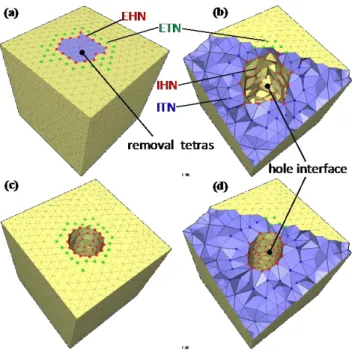
Figure 6 Creation of a through hole in a 3D mesh.
Figure 6 illustrates the whole process on a cube-like tetrahedral mesh. Figure 6.a and Figure 6.a.b show a mesh model before deformation. First, the removal tetrahedrons (RT) and hole interface nodes are
iden-DIRECT MODIFICATION OF FE MESHES PRESERVING GROUP INFORMATION
9
tified (Figure 6. 6.a). These tetrahedrons are then re-moved, the newly appearing boundary triangles con-stitute the HI and different node sets used by our technique are identified (Figure 6.b). Next, the con-straints are applied, and the solution in term of local deformation of the drilled hole is computed using the deformation engine (Figure 6.c and 6.d).
3.3. Extension to two new operators
Based on previously introduced operators, the cylin-drical crack and incision/cutting operators can easily be defined and implemented.
Figure 7. a, b, c illustrate the principle of the cylin-drical crack operator. Figure 7.a shows an initial mesh on which a cylindrical crack is performed. The profile is defined by a cylinder of center o and radius
r. In a first step, using an extension of the HI
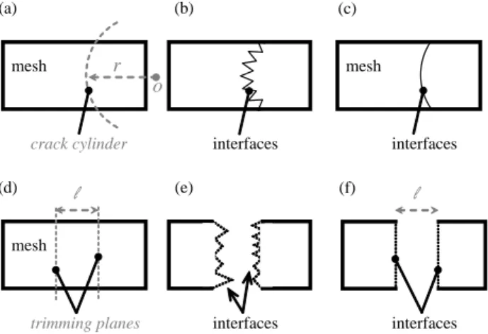
identi-fication process, the CI is detected (Figure 7.b) and handled similarly to the planar cracks (Figure 7.c). Figure 7.d, e, f present the principle of the incision operation. Figure 7.d shows an initial mesh on which an incision is performed. The incision is defined by two trimming planes and a distance between them. The first step involves the detection of all the mesh elements which are between the two cutting planes (Figure 7.e). This can be made using an extension of the crack model splitting. Next, the in-between ele-ments are removed, as for cylindrical hole. The two incision interfaces corresponding to the trimming planes are then handled similarly to the crack case (Figure 7.f).
(d) l (e) (f) l
mesh
interfaces
trimming planes interfaces
(a) (b)
r
(c) l
mesh
interfaces
crack cylinder interfaces
mesh
o
Figure 7 Overview of the two additional operators:
cylin-drical crack and cutting/incision operators.
4. FE MESH GROUP PRESERVING
4.1. On the use of group boundary
Maintaining and propagating semantic information during the mesh modification operation goes through the preserving of FE mesh group called structure lev-el (or low-levlev-el geometrical semantics). In particular, this involves an appropriate handling of mesh group geometry: group boundaries (geometrical and “virtu-al” boundaries), group shapes, topologies (nodes, edges, triangles,…), etc. In this work, we extend the definition and use of the so-called Virtual Group Boundaries (VGB) given in [2]. Roughly speaking, the VGB is defined by a set of 1D and/or 2D ele-ments located at the group frontier enclosing the 0D-3D groups (set of nodes or elements).
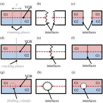
Nodes on VGB are used to apply additional con-straints during the local deformation to make these nodes staying on the shape of the group boundary. Figure 8 shows how to apply the mesh operations described in section 3 on a mesh enriched of two groups G1 and G2. The dashed line in Figure 8.a rep-resents the internal limit of the VGB of G1 and G2. Figure 8.b presents the result of removing all ele-ments between the two trimming planes various con-straints should be defined on the interface to preserve the planar shape of the cutting planes and the shape of the group boundary. All nodes on the incision in-terface should be constrained staying on the trim-ming plane and, in addition, all nodes on the VGB should maintain the geometry of the VGB (should stay on the given shape). The two nodes, which are simultaneously on the incision interface and VGB and represented by circles, have to stay on the trim-ming planes as well as on the VGB. Moreover, all nodes defining the VGB have to stay on the VGB. Figure 8.c shows the result of the deformation under constraints. Similarly, for crack (Figure 8.d to 8.f) and hole insertion (Figure 8.g to 8.i), specific con-straints are assigned to the nodes belonging to the VGB so that the shape of the VGB remains after de-formation. This is mandatory to be able to maintain the FE high-level semantic information (like BCs, modeling parameters, material characteristics, etc.) attached to groups G1 and G2.
(a) l (b) (c) G1
interfaces
trimming planes interfaces
G2 VGB (d) (e) (f) G1 interfaces cracking planes G2 VGB G1 G1 G1 G2 G2 G1 (g) (h) (i) G1 interfaces
Drilling cylinder interfaces
G2 VGB G1 G2 G2 G1 interfaces
Figure 8 Incision, crack and hole drilling operators
con-strained by the shape of the Virtual Group Boundaries.
4.2. Extended Group Boundary
The Virtual Group Boundary (VGB) introduced in [2] contains two sets: Bounding Elements (BE) and Isolated Elements (IE). The BE gathers together a set of elements of dimension dM – 1 (dM being the mesh
dimension) enclosing an area of dimension dM. The
IE groups mesh entities of dimension lower than dM
which do not cover the area of dimension dM by
themselves. For preservation of group information, depending on the associated mechanical high-level semantics, the area enclosed by BE can be re-meshed, and IE are forbidden to be modified. This concept is quite limit for the case where group of mesh entities have dimension lower than mesh but we want modify them.
Figure 9.a shows an industrial example of mesh un-ion operatun-ion: the additun-ion of two stiffeners onto a 2D triangle mesh of a caisson model. In this exam-ple, the original mesh contains a group of nodes (Gn) used to define displacement BCs (e.g. fixation of the structure). These nodes also correspond to the geo-metric boundary of the caisson. When adding a stiff-ener, a new node has to be inserted between the nodes n1 and n2 (Figure 9.c). Being Gn a group con-taining all the aligned boundary nodes, it seems meaningful to add the new node in Gn. However, according to the initial definition of VGB [2], all the nodes in Gn are considered as isolated (IE) which prevents the addition of the new node in Gn.
Figure 9 Example of triangle mesh merging: adding two
stiffeners on a caisson (courtesy EDF-R&D)
Therefore, to better handle these kinds of configura-tions, we extend the VGB definition by enabling the addition of so-called Linking Elements (LE). A LE contains the mesh elements of dimension lower than mesh and higher than node. During the mesh modifi-cation, the elements of LE can be split and new ele-ments obtained by splitting can be added to the group. These changes in the VGB structure slightly modify its computation as follows:
For group of faces in a 2D mesh, the computa-tion of VGB does not change [2].
For group of edges in a 2D mesh, the computa-tion of BE does not change [2]. All edges de-fined as isolated in [2] will be put into LE.
For group of nodes in a 2D mesh, the computa-tion of BE does not change [2]. The set of LE gathers together the edges associated to faces having exactly two group nodes and associated with exactly two group nodes. The set of IE con-tains the nodes associated to edges having only one node in the group.
For group of tetrahedrons in a 3D mesh, the computation of VGB does not change [2].
For group of faces in a 2D mesh, the computa-tion of BE does not change [2]. All faces de-fined as isolated in [2] will be put into LE.
For group of edges in a 3D mesh the computa-tion of BE does not change [2]. The set of LE gathers together the triangles which link to tet-rahedrons having less than 6 edges (in a given group) and which associate with exactly three group edges. The set of LE also gathers together the group edges which associate with any BE triangles and which associate with exactly 2 nodes in the group. The set of IE contains the nodes associated to edges having only one node in the group.
For group of nodes in a 3D mesh, the computa-tion of BE is the same as the one presented in the work [2]. The set of LE gathers together the triangles which associated to tetrahedrons
hav-DIRECT MODIFICATION OF FE MESHES PRESERVING GROUP INFORMATION
11
ing exactly three group nodes and which associ-ate with exactly three group nodes. The set of LE gathers also together the edges which associ-ate with triangles having exactly 2 nodes(in a given group) and which associate with exactly 2 nodes in the group. The set of IE contains the nodes associated to edges having only one node in the group.
As a conclusion, the BE elements enclose an area of dimension equal to mesh. This area can now be re-meshed so that new elements of group dimension can be added to the mesh group. The LE elements cover an area of dimension lower than mesh and more than a node. This dimension area can be split; and new split elements of group dimension can be added to the mesh group.
5. RESULTS
This section gives some results relative to the direct modification of industrial 2D/3D FE mesh models using our technique: insertion of different mesh fea-tures (crack, hole) following local deformation under constraints taking into account the shape of the group boundaries (low-semantics enriching the FE mesh).
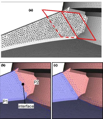
Figure 10 Insertion of a crack into the 2D mesh of a
cais-son model generated from a 3D mesh model (courtesy EDF-R&D).
The first example (Figure 10) shows a crack opera-tion performed on a surface mesh of the caisson mesh. Figure 10.a shows a part of the model where
one stiffener is located. Figure 10.b corresponds to the preparation step before deformation. The model is divided into two sub-mesh P1 and P2 according to the crack plane, and a crack interface is defined. Fig-ure 10.c presents the mesh after local deformation on the level of crack interface. On this example, 84 nodes have been moved onto the crack plane with 341 nodes moved in order to relax the transition mesh zone between fixed and free nodes. Therefore, 84 crack plane constraints and 425 tangent plane constraints have been used to accomplish accurately the required deformation.
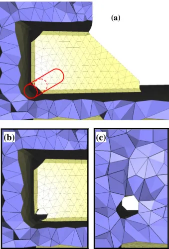
The second example (Figure 11) corresponds to the hole making operation performed on the tetrahedral mesh of the same caisson model. This operation is performed on the stiffener (Figure 11.a). Different mesh entity sets are identified to enable the specifica-tion of constraints required for deformaspecifica-tion of 3D elements located in the area of the given stiffener (Figure 11.b and Figure 11.c). On this example, 19 nodes have been moved onto the cylinder with 46 nodes moved on their tangent plane and 21 nodes defined as free to move. Therefore, 19 cylinder con-straints and 46 plane concon-straints have been used to accomplish accurately the required deformation. Another example illustrates the insertion of a cylin-drical hole into a cube-like mesh model on which two groups of tetrahedrons are defined. Here, not only it is important to obtain the hole, but also the boundaries of these groups have to be maintained. Figure 12.a shows the initial model on which the tet-rahedrons are separated into two mesh groups and shown separately on Figure 12.b and on Figure 12.c. Figure 12.d and Figure 12.f present the result of the through hole drilling operation without taking into account any group boundary. Whereas Figure 12.e and Figure 12.g give the result when preserving the shape of the 3D group boundary using different con-straints assigned to corresponding nodes. Red nodes are constrained to stay on the cylinder surface as well as on the group boundary (plane) for those nodes that are on the group boundary (e.g. n1). Blue nodes cor-responding to the transition mesh zone are free to move except for those which are on the limit of the two groups and that have to stay on a plane (e.g. n2).
(a)
(b)
(c)
Figure 11 Insertion of a cylindrical hole into the 3D mesh
of a caisson model (courtesy EDF-R&D).
6. CONCLUSION AND FUTURE WORKS
In this paper, a new framework for CAD-less FEA has been introduced. Actually, the geometric modifi-cations required during different optimization steps (mesh deformation or various modifications in order to take into account mesh quality criteria) are not anymore performed on the CAD models but directly onto the FE meshes enriched with their (low-, high-level) semantic information through the use of groups.
Several operators have been proposed to cover the primary needs in terms of direct mesh modification: 2D/3D crack and through hole operators. All these operators use a deformation engine using two types of constraints: those relative to the shape of the tools (e.g. cylinder for hole and plane for crack), and those relative to the shape of the group boundaries that have to be preserved. The mesh is modified in a bandwidth so that the quality of the elements (e.g. their aspect ratio) remains good with respect to the FEA requirements. The proposed operators reposi-tion nodes without adding new ones. If the operated
mesh does not have enough nodes in the modification area, a mesh pre-refinement step is necessary.
In the future, we would like to extend our mesh mod-ification toolbox to other shapes (e.g. spheres, torus or free form) as well as to other operators such as material addition which is often required for fast modifying of advanced FE mesh models.
Figure 12 example of mesh drilling operation by
preserv-ing the group boundary
ACKNOWLEDGMENTS
This work is partially supported by the Research and Development direction of the EDF Group, and it is partially carried out within the scope of the FOCUS K3D project supported by the European Commission [13]
REFERENCES
[1] J.P.Pernot, B.Falcidieno, F.Giannini, J.C.Leon, 2008, Hybrid models deformation tool for free form shapes manipulation, Proc. of the ASME 2008 Int. Design Eng. Tech. Conf. & 34th Design Automation Conf., DETC08-DAC49524, New-York, USA.
[2] R.Lou, F.Giannini, J.P.Pernot, A.Mikchevitch, B.Falcidieno, P.Veron, R.Marc, 2009, Towards
cad-DIRECT MODIFICATION OF FE MESHES PRESERVING GROUP INFORMATION
13
less finite element analysis using group boundaries for enriched meshes manipulation, Proc. of the ASME 2009 Int. Design Eng. Tech. Conf. & Com-puters and Information in Eng. Conf., DETC09-CIE86575, San Diego, USA.
[3] A.Mikchevitch, S.Geniaut, I.Nistor, 2009, Towards fast numerical studies for maintenance and lifecycle problem analysis: New simulation methods on exam-ple of an industrial study case, Proc. of ASME Int. Pressure Vessels and Piping Division Conf. PVP'2009, PVP2009-77154, Prague, Czech Repub-lic.
[4] R.S.Barsoum, 1974, Application of quadratic isopa-rametric elements in linear fracture mechanics, Int. J. of Fracture, 10:603-605.
[5] T.Strouboulis, I.Babuska, K.Copps, 2000, The design and analysis of the generalized finite element meth-od. Int. J. for Comp. Methods in Applied Mechanics and Engineering, 181:43-69.
[6] E.Bechet, H.Minnebo, N.Moes, B.Burgardt, 2005, Improved implementation and robustness study of the X-FEM for stress analysis around cracks. Int. J. for Num. Methods in Engineering, 64(8):1033-1056. [7] M.Schoellmann, M.Fulland, H.A.Richard, 2003, De-velopment of a new software for adaptive crack growth simulations in 3D structures, Int. J. of Engi-neering Fracture Mechanics, 70(2):249-268.
[8] N.Moes, J.Dolbow, T.Belytschko, 1999, A Finite Element Method for Crack Growth Without Remesh-ing, Int. J. for Numerical Methods in EngineerRemesh-ing, 46(1):131-150.
[9] D.Bremberg, G.Dhondt, 2008, Automatic crack-insertion for arbitrary crack growth. Int. J. of Engi-neering Fracture Mechanics 75:404–416.
[10] A. Martinet, E. Galin, B. Desbenoit, S. Akkouche, 2004, Procedural modeling of cracks and fractures, Int. Conf. on Shape Modeling and Applications, pp. 346-349.
[11] H-W. Nienhuys, A. F. van der Stappen, 2001, Sup-porting cuts and finite element deformation in inter-active surgery simulation, Technical Report, Univer-siteit Utrecht.
[12] K.Kundu, M.Olano, 2007, Tissue Resection using Delayed Updates in a Tetrahedral Mesh, Proc. of Medicine Meets Virtual Reality 15, Eds. J.D.Westwood and al., IOS Press, Netherlands. [13] Foster the Comprehension and Use of Knowledge
intensive 3D media, FP7 Coordination Action, www.focusk3d.eu
[14] Z.Ji, L.Liu, Z.Chen, G.Wang, 2006, Easy Mesh Cut-ting. Proceedings of Eurographics, Vienna, Austria, Computer Graphics Forum, 2006, 25(3): 283-291.
[15] G.Turini, G.Ganovelli, C.Montani, Simulating Drill-ing on Tetrahedral Meshes, 2006, ProceedDrill-ings of Eu-rographics Conference - Short Papers, p. 127-131 [16] G.Turkiyyah, W.B.Karam, Z.Ajami, A.Nasri, 2009
,Mesh cutting during real-time physical simulation, Symposium on Solid and Physical Modeling, p. 159-168
[17] C. D. Bruyns, S. Senger, A. Menon, K. Montgomery, S. Wildermut, R. Boyl, 2002, A survey of interactive mesh-cutting techniques and a new method for im-plementing generalized mesh cutting using virtual tools. The journal of visualization and computer ani-mation, 13, pp. 21- 42.
[18] D. Bielser, A. Volker, M. Gross, 1999, Interactive cuts through 3-dimensional soft tissue. Computer Graphics Forum 18-3 (1999), pp. C31–C38
[19] P, Kršek, 2002, Complex human tissues fem models prepared by boolean operations, In: Biomechanics of man 2002, Praha, CZ, UK FTVS, p. 24-26, ISBN 80-86-317-23-4
[20] M. Dakowicz, C. M. Gold, 2005, Interactive TIN modification with a cutting tool. In: Proceedings, IS-PRS Workshop on Dynamic and Multidimensional GIS.