En vue de l'obtention du
DOCTORAT DE L'UNIVERSITÉ DE TOULOUSE
Délivré par :
Institut National Polytechnique de Toulouse (INP Toulouse)
Discipline ou spécialité :
Génie Électrique
Présentée et soutenue par :
M. DAVID MAGIN FLOREZ RUBIO
le lundi 20 janvier 2014
Titre :
Unité de recherche :
Ecole doctorale :
SOURCES D'ALIMENTATION ELECTRIQUE POUR L'ETUDE ET
L'UTILISATION EFFICACE DES LAMPES EXCIMER DBD
Génie Electrique, Electronique, Télécommunications (GEET)
Laboratoire Plasma et conversion d'Energie (LAPLACE)
Directeur(s) de Thèse :
M. HUBERT PIQUET M. RAFAEL DIEZ
Rapporteurs :
M. DIEGO ECHEVERRY, UNIVERSIDAD DEL VALLE M. MARCOS ALONSO, UNIVERSIDAD DE OVIEDO
Membre(s) du jury :
1 M. FREDY RUIZ, PONTIFICIA UNIVERSIDAD JAVERIANA BOGOTA, Président
2 M. GEORGES ZISSIS, UNIVERSITE TOULOUSE 3, Membre
2 M. HUBERT PIQUET, INP TOULOUSE, Membre
i
Acknowledgements
The works presented in this doctoral thesis have been developed within the research groups CEPIT of the Pontificia Universidad Javeriana in Bogota, Colombia, and G-ENESYS of the Laboratoire Plasma et Conversion d’Energie (LAPLACE), unité mixte de recherche CNRS-INPT-UPS nº 5213 in Toulouse, France.
The financial support of this doctoral thesis has been provided by: the Colombian national agency for the science and technology COLCIENCIAS, COLFUTURO, la
cor-poration pour les études en France CEF from the french ambassay in Bogota and the
bi-national program ECOS-NORD.
To begin I express my sincere gratitude to Professors Marcos Alonso, Diego Echeverry, and Georges Zissis for accepting to examine this work, for their valuable review and constructive discussions. In the same manner, I acknowledge Professor Fredy Ruiz for his valuable cooperation being the president of the Jury, facilitating the well development of the multi-national exam committee.
The Directors of this thesis, Professor Rafael Diez and Professor Hubert Piquet, de-serve my genuine gratefulness for allowing me to being part of their motivating re-searches, for their engaged guidance of my work and for transmitting to me their rigorous research methodology. The accomplishment of this thesis co-direction has been possible thanks to their commitment with the international scientific cooperation.
Furthermore my thankfulness is:
In Colombia to Dr. Carlos Parra, Director of the Doctorado en Ingeniería at Pontificia Universidad Javeriana for receiving me at the program and for his support for the well development of the international co-direction. To Professors Karim Hay, Gabriel Perilla and Camilo Otálora for apporting their ideas, experience and knowledge to the project. In France to Monsieur Christian Laurent and Monsieur Maurice Fadel, Directeur and Directeur Adjoint respectively, of the LAPLACE for accepting me to be part of the laboratory. To Monsieur Xavier Roboam, Director of the G-ENESYS group, for his gen-tle receiving among a team of exceptional professionals and researchers. To Monsieur Eric Bru, from who I really appreciate the constant and kindly cooperation and helpful teachings during my stays at LAPLACE laboratory. To Monsieur Jean-Marc Blacquiere for his valuable advise for the improvement and implementation of the converters de-veloped during this research and to Monsieur Sebastien Vinnac for his help with the implementation. To Monsieur Antoine Belinger for his active participation at the eval-uation process of my doctoral studies and his help with the spectrometry of the lamp. To Monsieur Sounil Bhosle for his fundamental contribution providing the project with the DBD Excilamps and help in the understanding of this technology.
To the society Trojan UV, in particular to Dr. Gordon Knight and Farnaz Daynouri for receving me at their headquarters and allowing me to learn about their research units.
I say thanks in a more familiar way to:
Xavier Bonnin pour sa grande contribution au projet de recherche avec ses développe-ments sur le transformateur et surtout pour sa visite en Colombie, son amitié et générosité
ii
pendant mon séjour en France; ce remerciement est extensive bien sur á Virginie, Yann et Cassandre pour leur aimable accueil chez eux.
Alaric et Priscilla Montenon pour leur amitié, les gentilles invitations et les délicieux repas.
Djibrillah pour sa visite en Colombie et son aide lors de mes premiers jours au LAPLACE.
Agradezco a Diego Botero por su generosidad, simpatía y ayuda incondicional durante mis estadías en Toulouse sin las cuales no me habría divertido tanto, también le quiero agradecer por habernos esperado estóicamente en medio de la nieve.
A mi familia entera, quienes me han alentado y apoyado en todo sentido durante los momentos difíciles de esta aventura. Estoy seguro que no habría logrado llegar a realizar este doctorado sin los valores y enseñanzas que Stella y Aroldo nos inculcaron.
Finalmente a mi amada Malu, por tantos años, tantos viajes y tantos paisajes. A ella corresponde gran parte del buen término de esta tesis.
iii Résumé: Avec l’objectif d’améliorer le rendement des lampes à excimères (Excil-ampe) à décharge à barrière diélectrique (DBD), un convertisseur en mode de courant, qui permet un ajustement précis de la puissance électrique injectée dans ce type des lampes, à été conçu et mis en œuvre. Ce convertisseur fournit à la lampe un courant de forme d’onde carrée contrôlé au moyen de trois paramètres: l’amplitude, la fréquence et le rapport cyclique, pour obtenir un contrôle total de l’énergie électrique transmise à l’excilampe DBD. La mise en œuvre intègre un transformateur élévateur comme in-terface entre la lampe et un commutateur. Les expériences démontrent le principe de fonctionnement de ce convertisseur, y compris les mesures de puissance du rayonnement UV. Les degrés de liberté du convertisseur sont utilisées pour analyser le comportement de la lampe sous différentes combinaisons de ces trois paramètres, et sont utilisés pour déterminer le point de fonctionnement optimal de la lampe. Ensuite, un convertisseur à résonance du type onduleur série, est proposé pour alimenter la lampe avec une grande efficacité électrique. Afin de contrôler effectivement la puissance de la lampe, le mode de fonctionnement de ce convertisseur utilise le mode de conduction discontinue et la commutation douce (ZCS), avec lequel on obtient aussi de faibles émissions électromag-nétiques et l’on réduit les pertes de commutation. Les relations mathématiques obtenus à partir de l’analyse du diagramme de phase, ont été validées par des simulations et avec des résultats expérimentaux. Enfin, différentes topologies d’alimentations pour DBD sont comparées analytiquement et expérimentalement pour évaluer objectivement les avantages de chaque approche. Une des perspectives de ce travail est l’application de l’alimentation en créneaux pour l’étude de la performance d’autres types de réacteurs et d’excilampes DBD.
Mots clef: DBD, lampe à excimères, source de courant, convertisseur à résonance, UV. Abstract: With the aim to provide a scientific tool for the enhancement of the Dielec-tric Barrier Discharge (DBD) Excimer Lamps (Excilamp) performance, a current-mode converter that allows an accurate adjustment of the electrical power injected into one of those lamps, is designed and implemented. With the proposed converter, the cur-rent supplied to the lamp has a square shape, controlled by means of three parameters: amplitude, duty cycle and frequency, which provides full control of the lamp electri-cal power. Implementation is made considering a step-up transformer interfacing the high-voltage lamp with the converter. Experiments demonstrate the operating principle of this converter, including UV power measurements for a DBD XeCl Excilamp. The capabilities of the converter are used to analyze the lamp behavior under different com-binations of these three parameters, illustrating its capabilities for finding the optimal operating point. Then a series-resonant inverter for the supply of DBD) excilamp is proposed. In order to effectively control the lamp power, the operating mode of this converter combines discontinuous current-mode and soft-commutation (ZCS), obtaining as well low electromagnetic emissions, and reduced switching losses. The mathemati-cal relationships obtained from state plane analysis, are validated with simulations and experimental results. Finally, several topologies of DBDs power supplies are compared analytical and experimentally to elucidate the advantages of each approach. After this
iv
work, one of the perspectives is the application of the square-shape supply in the per-formance study of other types of DBD excilamps and DBD reactors.
Contents
Introduction 1 1. Literature review 9 1.1. DBD Excimer UV lamps . . . 9 1.1.1. Operating Principle . . . 9 1.1.2. Operating Conditions . . . 11 1.1.3. Modeling . . . 141.2. Power supplies for DBDs . . . 16
1.2.1. Controlling the DBD excilamp power . . . 16
1.2.2. Current Mode Supplies for DBDs . . . 18
1.2.3. Voltage Mode Supplies for DBD . . . 23
1.3. Characteristics of Commercial DBD Excilamp Based Systems . . . 26
1.4. Summary . . . 27
2. Parametric Control of the DBD Excilamp Electrical Power 33 2.1. Control of Lamp Power with Three Degrees of Freedom . . . 33
2.1.1. Choice of the Current Waveform . . . 33
2.1.2. Lamp Power Computation . . . 34
2.2. Square-shape Current Supply Design . . . 36
2.2.1. Current Inverter Operation . . . 36
2.2.2. Constant Current Source . . . 38
2.3. Considerations for implementation . . . 45
2.3.1. Frequency of the Lamp Current . . . 45
2.3.2. Output Current and Voltage . . . 45
2.3.3. The Step-up Transformer . . . 46
2.4. Components selection . . . 50
2.4.1. Transformer . . . 50
2.4.2. Inductance . . . 57
2.4.3. Switches . . . 57
2.5. Implementation Results . . . 57
2.5.1. User Interface for the Operating Point Adjustment . . . 58
2.5.2. Experimental Bench . . . 59
2.5.3. Lamp Power Adjustment . . . 59
2.5.4. Efficiency . . . 62
2.5.5. UV radiation . . . 64
vi Contents 3. Parametric Study of the Operating Point Influence on the DBD Excilamp
Performance 69
3.1. Experimental Set-up . . . 70
3.2. Impact of the Lamp Current Intensity . . . 72
3.2.1. Impact of J Over the UV Production . . . 72
3.2.2. Impact of J Over the Electrical and UV Waveforms . . . 74
3.2.3. Impact of J Over the Lamp Model Parameters . . . 76
3.2.4. Impact of J Over the Discharge Regime . . . 77
3.3. Impact of the Lamp Operating Frequency . . . 79
3.3.1. Impact of flp Over the UV Production . . . 79
3.3.2. Impact of flp Over the Electrical and UV Waveforms . . . 80
3.3.3. Impact of flp Over the Lamp Model Parameters . . . 82
3.3.4. Impact of flp Over the Discharge Regime . . . 83
3.4. Best Performance Operating Conditions . . . 84
3.5. Conclusions . . . 86
4. High Efficiency DBD Power Supply Working at the Optimal Operating Point 91 4.1. Topology: SRI Operated in DCM . . . 91
4.1.1. State plane analysis . . . 94
4.1.2. State plane: before breakdown trajectory . . . 94
4.1.3. State plane: after breakdown trajectory . . . 96
4.1.4. Operating conditions . . . 97
4.2. Components Selection and Simulations . . . 103
4.2.1. Operating Point . . . 103 4.2.2. Switches . . . 103 4.2.3. Step-up Transformer . . . 104 4.2.4. Inductance Value . . . 104 4.2.5. Simulations . . . 105 4.3. Experimental Results . . . 107 4.3.1. Electrical Waveforms . . . 107 4.3.2. Performances . . . 109 4.4. Conclusions . . . 111 5. DBD Supplies comparison 113 5.1. Analytical Design . . . 115
5.1.1. Boost Based Converter . . . 115
5.1.2. Buck-Boost based converter . . . 120
5.2. Converters Design and Simulations . . . 124
5.2.1. SRI design . . . 124 5.2.2. Boost-based design . . . 126 5.2.3. Buck-Boost-based design . . . 128 5.2.4. Square-shape design . . . 129 5.2.5. Simulations . . . 130 5.3. Experimental results . . . 131
Contents vii 5.4. Conclusions . . . 133
6. General Conclusions 135
A. Appendix. Résumé de la Thèse en Français 153
List of Figures
0.1. UV absorbance of the DNA [0.4, p. 2-7] . . . 2
0.2. Main UV artificial sources. From left to right: LED [0.8], HID Mercury-vapor lamp [0.9], HID Xenon lamp [0.10] and DBD excimer lamp . . . 3
1.1. Structure of a DBD lamp with planar geometry . . . 10
1.2. Illustration of the electrons (e−) avalanche and the produced local electric field Elocal. Once the direction of the external electric field has changed, the local field remnant helps to the production of the next streamer. . . 10
1.3. Collisions in a DBD excimer lamp filled with XeCl gas. . . 11
1.4. Lower excited states of energy (B, C, D) of an exciplex and the radiative transi-tions to the ground state (A, X). As appears in [1.4, p. 194] . . . 12
1.5. Electrical model of the DBD lamp . . . 14
1.6. Structure of a coaxial DBD lamp. . . 15
1.7. Charge-Voltage Lissajous figure of an ozone reactor [1.18, p. 13] . . . 16
1.8. Lamp current path before (left) and after (right) gas breakdown. . . 17
1.9. Left: Boost-based DBD power supply designed to operate in DCM [1.22]. Right: the corresponding lamp voltage and current waveforms obtained from simulation. 19 1.10.Left: The Adaptive Pulse topology proposed in [1.23, p. 85,144] Right: the corresponding lamp voltage and current waveforms obtained experimentally. . . 20
1.11.Left: Flyback topology based DBD power supply designed to operate in current-mode. Right: the corresponding lamp voltage and current waveforms obtained from simulation. . . 21
1.12.Left: Buck-Boost topology based DBD power supply designed to operate in current-mode. Right: the corresponding lamp voltage and current waveforms obtained from simulation. . . 22
1.13.Experimental waveforms of the Buck-Boost-based converter operating in DCM. Left: Inductance current iL and lamp current ilamp Right: Computed conduc-tance current igas and measured UV instantaneous response UV . [1.6]. . . 22
1.14.Left: Universal-sinusoidal topology based on the Buck-Boost topology, proposed in [1.27]. Right: The experimental DBD voltage and current burst. . . 23
1.15.Schematic of a voltage-pulse generator [1.35, p. 601] (A) and a Forward based sinusoidal voltage source [1.20] (B) . . . 24
1.16.Top: Schematic used for simulation of a voltage source connected to the DBD excilamp. Bottom: The DBD lamp voltage and current simulated waveforms, obtained for an imposed voltage are shown. . . 25
x List of Figures 2.1. Square-waveform current applied to the lamp ilp, the gas conductance current
iG (top) and voltages calculated using the lamp model (bottom). . . 34
2.2. Topology of the two-quadrant chopper based DBD Power Supply . . . 36
2.3. Example sequence of the inverter switches control signals . . . 37
2.4. Inverter switches characteristic. . . 37
2.5. Theoretical waveform of vbridge according to (2.2.1) . . . 38
2.6. Output current ripple with fc < flp (top) with the corresponding inverter and control voltage (bottom). A current spike exceeding the hysteresis limits is ob-served, this spike occurs because Vin< ˆVlp. . . 40
2.7. Minimum value of L as a function of Vin to obtain: a controller operating fre-quency below 40 kHz (solid line) and a maximum controller error equal to 5% of J (dashed line). Values calculated using (2.2.10) and (2.2.16) respectively, with the following parameters: ∆hyst = 5%(J), Vth=1.3 kV, Cd=85 pF, Dlp=1, flp=50 kHz, J=300 mA. . . . 44
2.8. Current source switches characteristic. . . 44
2.9. Lamp power as a function of the lamp current frequency, for different values of ˆVlp. 46 2.10.Transformer model with the parasitic elements. . . 47
2.11.Simulation waveforms illustrating the impact of the transformer parasitic elements 49 2.12.Transversal view of the transformer coils arrangement . . . 51
2.13.Low-capacitance transformer Bode plot . . . 52
2.14.Comparison of the experimental and calculated Bode plots. . . 53
2.15.Waveforms obtained using the low-capacitance transformer without connection to ground (left) and with connection of one terminal to ground (right) . . . 54
2.16.Transformer model to explain the grounding effect . . . 54
2.17. . . 55
2.18.Alternative transformer Bode plot . . . 55
2.19.Waveforms obtained using the first (top) and the new transformer (bottom) with-out connection to ground (left) and with connection of one terminal to ground (right). For the second transformer, igndis substantially reduced and the lamp ignition is achieved. . . 56
2.20.Screen-shot of the software interface used to define the converter operating point 58 2.21.Square-shape DBD Power supply blocks diagram. . . 58
2.22.Constant amplitude current pulses injected into the lamp for different flp values (left) and the corresponding vlp waveform (right) . . . 59
2.23.For a given frequency, the same lamp power can be obtained for different com-binations of J and Dlp . . . 60
2.24.Lamp power as a function of the lamp current amplitude, for flp= 80 kHz. The duty cycles are placed next to data points. . . 60
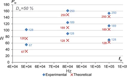
2.25.Lamp power as a function of the lamp current frequency, for Dlp= 50%. The J values (in mA) are placed next to data points. . . 61
2.26.Lamp power as a function of the lamp current duty cycle, for J = 189 mA. The lamp operating frequencies (in kHz) are placed next to data points. . . 62
List of Figures xi 2.27.Lamp voltage, current and UV instantaneous response, for three operating points
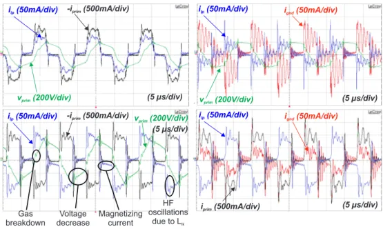
near to the maximum output voltage and current of the converter. . . 63 3.1. DBD excilamp dimensions. A picture of the actual lamp is superposed to the
lamp drawing in order to show the aspect of the electrodes . . . 70 3.2. Experimental bench. . . 70 3.3. Left: Change in the temperature of the excilamp electrodes for a particular
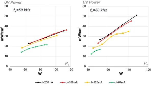
operating point. Right: Excilamp UV power variation in the time due to heating, for a particular operating point. . . 71 3.4. Impact of the excilamp current intensity in the UV output for flp=50 kHz (left)
and flp=80 kHz (right) . . . 72
3.5. Impact of the excilamp current intensity in the UV output for flp=110 kHz (left)
and flp=140 kHz (right) . . . 73
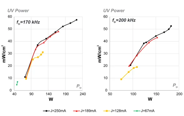
3.6. Impact of the excilamp current intensity in the UV output for flp=170 kHz (left)
and flp=200 kHz (right) . . . 74
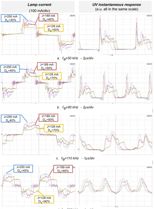
3.7. Comparison of the current and UV waveforms for different values of J . . . 75 3.8. The experimental lamp current and UV (in arbitrary units) waveforms are shown
together in order to demonstrate the similarity between both signals. flp=80 kHz 76
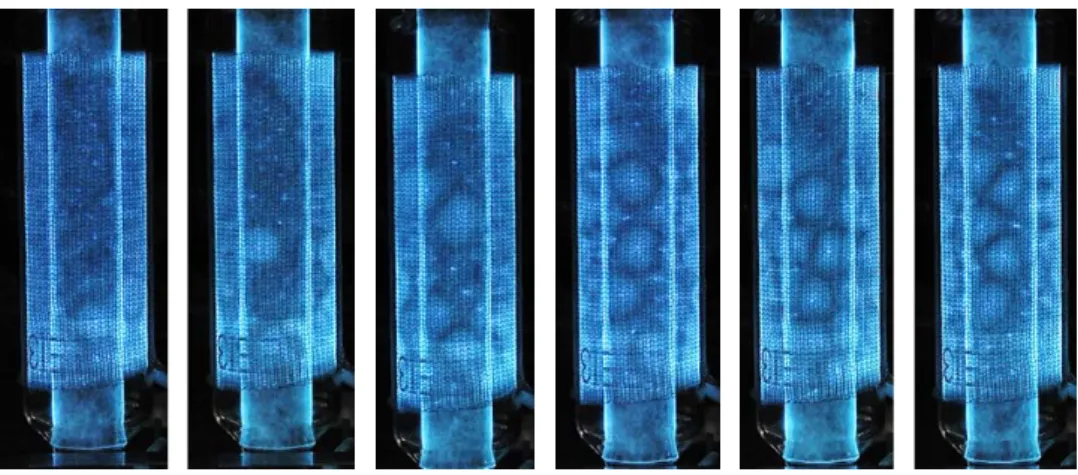
3.9. Lamp Charge-Voltage plot for different values of current intensity at constant current frequency and injected power. . . 77 3.10.Changes in the visual aspect of the discharges with the increase of the current
intensity. flp= 70 kHz, Plp= 80 W , J = 95, 116, 133, 154, 171, 186 mA (from
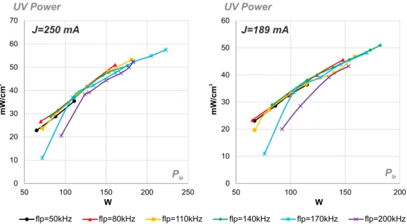
left to right) . . . 78 3.11.Impact of the operating frequency in the UV output for J=250 mA (left) and
for J=189 mA (right) . . . 79 3.12.Impact of the operating frequency in the UV output for J=128 mA (left) and
for J=67 mA (right) . . . 80 3.13.Comparison of the current and UV waveforms for J = 250mA . . . 81 3.14.Lamp Charge-Voltage plane for different values of current frequency at constant
current intensity and injected power. . . 83 3.15.Changes in the visual aspect of the discharges with the increase of the operating
frequency. flp= 50, 60, 70, 80, 90, 100 kHz (from left to right), Plp=80 W, J=100
mA . . . 84 3.16.Excilamp relative radiation efficiency as a function of the injected energy, for
different values of lamp current intensity (left) and lamp operating frequency (right) . . . 85 3.17.Excilamp UV power as a function of the injected electrical power, with the
corresponding lamp current frequency (left) and lamp operating intensity (right) 86 4.1. The proposed series-resonant inverter . . . 92 4.2. The SRI operating sequences (bottom). Theoretical waveforms for lamp current,
lamp voltage and gas voltage (top). . . 93
xii List of Figures 4.3. Two operating conditions before breakdown are plotted in the state plane: When
the gas breakdown happens before the peak current (left) and after the peak current (right). Only the positive current half-cycle is shown. . . 95 4.4. Two operating conditions are plotted in the state plane after breakdown: When
the gas breakdown happens before the peak current (left) and after the peak current (right). Only the positive current cycle is shown. . . 96 4.5. Transient response from simulation. Unstable state plane for V in > V th (left),
stable state plane for V in < V th (right). . . . 98 4.6. Theoretical lamp power as a function of the converter input voltage, calculated
with (4.1.39) (Vth=1.31 kV, Cg=28 pF, Cd=85 pF). Vink is the limit between
operating cases A and B. Vthis the asymptote of the Plp function. . . 102
4.7. Converter circuit and DBD electrical model used for simulation . . . 104 4.8. Waveforms comparison from simulation (top) and from the experimental
valida-tion (bottom). flp= 80kHz, Vin= 115V . . . 105
4.9. Theoretical lamp power as a function of the converter input voltage calculated with (4.1.39) and simulation results including the transformer parasitic elements (Vth=1.31 kV, Cg=28 pF, Cd=85 pF). . . 106
4.10.Experimental electrical waveforms of the lamp, the transformer primary side voltage and the inductance current. . . 108 4.11.Theoretical, simulated and experimental lamp power as a function of the
con-verter input voltage. The theoretical values are calculated with (4.1.39) (Vth=1.31
kV, Cg=28 pF, Cd=85 pF). The schematic used for simulation is presented in
Fig.4.7 . . . 108 4.12.Measured efficiencies of the SRI for different values of output power at flp=80kHz.109
4.13.UV waveform and Excilamp current for the SRI.. . . 110 4.14.FFT of the lamp current for SRI and Square waveform current-source topologies. 111 5.1. Schematics of the DBD supplies under study. . . 114 5.2. Boost-based converter operating sequences (top) with the output current
wave-form (bottom). . . 116 5.3. State planes for the Boost-based converter in DCM. Before (left) and after (right)
gas breakdown. For two operating cases: When the gas breakdown happens before the peak current (A) and after the peak current (B) . . . 117 5.4. Power delivered to the lamp by the Boost-based converter for different values of
inductance charge time. . . 118 5.5. Buck-Boost-based converter output current waveform (bottom) with the
corre-sponding operating sequences (bottom) . . . 121 5.6. State planes for the Buck-Boost-based converter in DCM. Before (left) and
af-ter (right) gas breakdown. For two operating cases: When the gas breakdown happens before the peak current (A) and after the peak current (B) . . . 122 5.7. Power delivered to the lamp by the Buck-Boost-based converter for different
List of Figures xiii 5.8. For an operating frequency flp=60 kHz, the inductance charge time, Tch, plus
the lamp current pulse, Tpulse, must be smaller than Tlp/2=8 µs. In this figure,
Tch+ Tpulse is plotted as function of Vin.. . . 127
5.9. Simulation waveforms of the four topologies. . . 130 5.10.Experimental waveforms of the four topologies. Plp= 106W , flp= 60kHz . . . 132
List of Tables
2.1. Equivalent electrical parameters of a XeCl DBD Excilamp . . . 45 2.2. Comparison of some High-Voltage MOSFET devices specifications (Source:
www.digikey.com) . . . 47 2.3. Transformer materials and construction characteristics . . . 51 2.4. Alternative transformer and converter efficiencies . . . 57 2.5. Converter efficiency for different inverter frequencies, with ˆVlp=5 kV and
J=250 mA . . . 62 3.1. Equivalent lamp parameters and standard deviation obtained from the
Charge-Voltage Lissajous figures shown in Fig.3.9 . . . 77 3.2. Equivalent lamp parameters and standard deviation obtained from the
Charge-Voltage Lissajous figures shown in Fig.3.14. J=250 mA . . . 82 3.3. Point of maximum lamp efficiency within the operating range of the
ex-periments . . . 85 4.1. Theoretical operating point . . . 103 5.1. Main equations of the four topologies. . . 125 5.2. Operating Point for the SRI converter. Vin = 1175V V , L = 25 mH . . . . 126
5.3. Operating Point for the Boost-based converter. Vin = 850V , L = 28.3mH,
Tch= 4.36 µs . . . 128
5.4. Operating Point for the Buck-Boost-based converter. Vin = 2.4 kV , L =
38.1 mH, Tch= 3.32 µs . . . 129
5.5. Operating Point for the Square-shape converter. . . 129 5.6. Converters efficiencies comparison. Electrical power supplied to the lamp:
Introduction
As reported by the United Nations “in the year 2011, 768 million people were still without access to improved sources of drinking water while 2.5 billion people did not use improved sanitation” [0.1]. In the particular case of Colombia, the quality of the drinking water provided at the 35% of rural areas does not meet the required standards [0.2] and most of the superficial water sources are not ready for human consumption [0.3]. This harmful situation for many communities, is at the origin of this doctorate work.
This thesis is developed in the context of a research project that aims for the design and implementation of a water disinfection system prototype, based on UV radiation generated by a Dielectric Barrier Discharge excimer lamp. This project is supported by COLCIENCIAS, ICETEX, and the ECOS-NORD program.
The Dielectric Barrier Discharge excimer lamps (DBD excilamps) is an emerging and competitive technology for the efficient production of Ultra-Violet radiation (UV). The UV has well known germicidal properties and the use of UV in disinfection brings several advantages when compared with chemical based methods. The benefits of the DBD excimer lamps (presented later in this Section) together with the advantages of the UV radiation to decontaminate, have motivated the proposal of a water decontamination system based on this technology.
The development of the proposed water decontamination system, implies the con-currence of diverse areas of knowledge like bacteriology, hydrology, mechanics, plasma science and electronics. In this doctoral thesis, we are focused in a particular aspect of the decontamination system: the challenge of enhancing the performance of the DBD excilamp as UV source and the development of a high efficiency power supply for this lamp technology. Although, given the context of this research, the DBD UV excilamps is the focus of our interest, it is important to note that the developments proposed in this thesis can be pertinent for other type of DBD reactors.
What is the Ultra-Violet (UV) Radiation Useful for? The sun is the only natural source of UV radiation found in earth and its UV radiation plays an important role in natural processes, for example for the human beings synthesis of vitamin D and the natural control of microorganisms concentrations due to the UV germicidal property. The germicidal property of the UV is caused in part by the damage that the UV radiation can produce to the cells Nucleic Acids. The DNA absorption at different wavelengths of UV is shown in Fig.0.1, which gives the radiation wavelengths that causes more damages to cells.
For years the germicidal property of the UV radiation has been exploited in decon-tamination systems employing artificial UV sources [0.5] and nowadays a wide range of
2 Introduction
Figure 0.1.:UV absorbance of the DNA [0.4, p. 2-7]
industry and medical processes implement the photo-chemical reactions generated by the UV, among them the micro-lithography [0.6], skin treatment, light production and resin curing [0.7].
Particularly on the field of the water treatment, the UV based systems are advan-tageous when compared with classical Chlorine, Ozone and Peroxide based methods: the UV does not affect the physic-chemical properties of the water nor produce harmful sub-products and avoid the need for stock of reactive chemicals [0.5], making the UV a good option for their use in isolated rural areas. To generate UV radiation several technologies are available.
Artificial UV Sources The main artificial sources of UV radiation are presented in Fig. 0.2. The UV LED radiates typically in wavelengths (385 nm) that are not very effective to decontaminate as shown in Fig.0.1.
For germicidal systems, the High Intensity Discharge (HID) Mercury-vapor based lamp is widely used. Its radiation spectra changes depending on the gas mixture pressure. In low-pressure lamps the radiation presents two main peaks, in 185 and 254 nm, in contrast, in medium-pressure lamps a polychromatic spectrum is observed with approximately only the 30% corresponding to UV. The Mercury content of this type of lamps can be dangerous for the environment and is strictly regulated. However not only the Mercury-vapor is used in HID lamps to produce UV; the HID Xenon lamps provides high intensity UV radiation flashes with an almost continuous spectra from the UV up to the Infrared radiation, useful e.g. to simulate the sun light. Thus, if a specific wavelength is required, a large amount of its radiated power becomes useless.
Another type of Mercury free UV sources are the DBD excilamps. This type of lamp is made from a sealed crystal bulb filled with an halogen gas, or halogen-rare gas mixture. Differing from the HID lamps, the metallic electrodes are placed outside of the crystal bulb. Its radiation wavelength depends on the gas mixture used and is quasi mono-chromatic. Compared with the other UV sources, the DBD excilamp technology
3
Figure 0.2.:Main UV artificial sources. From left to right: LED [0.8], HID Mercury-vapor lamp [0.9], HID Xenon lamp [0.10] and DBD excimer lamp
present special features well adapted for the requirements of several applications. Next, we describe these characteristics.
Main Advantages of the DBD Excilamps Compared with the other UV artificial sources, the DBD excilamp presents the following distinctive features:
• It is mercury free. Consequently can be used in environments where the mercury content is hazardous, e.g. in the food and medicament industry.
• The electrodes are not in contact with the gas. Consequently, differing from the conventional discharge lamps, the electrodes are not deteriorated by the discharge. • Instantaneous ignition. This implies no need for warm up time and immediate
availability.
• Offers a wide radiation surface due to its geometry.
• The radiation wavelength is very precise and depends mainly on the gas compo-sition, which can be selected according to the microorganism to be treated or the particularities of the application.
The DBD excilamps are nowadays focus of active research and the lamp performances continues to be improved. However, many years of research and developments are behind this technology.
DBD Excilamps Technology Landmarks The origin of the DBD excilamps technology can be traced back to the first dielectric-barrier discharges investigations (1865) [0.11]. Since 1955 earlier reports on the Vacuum UV and UV radiation emission from rare gases were published [0.12,0.13,0.14,0.15,0.16,0.17] and an extensive review discussing the for-mation of excimers and its properties dates from 1975 [0.18]. A pioneer work integrating the excimer UV production and DBD, appears in 1988 [0.19], followed by many original works reporting the enhancement of the excilamps efficiency [0.20,0.21] and power [0.22], proposing excilamp models [0.23] and patenting excilamp devices [0.24, 0.25]. Authors in [0.26] proposed the first experiments with pulsed power supplies enhancing the excil-amp efficiency (previously supplied with sinusoidal voltage generators). Later in [0.27]
4 Introduction the current mode power supply for this application, was proposed. One of the first re-ported works of decontamination using UV from DBD excilamps is [0.28], published in 2001. The research in excilamps for UV production continues and extensive reviews of the excilamps technology and their applications can be found in [0.11, p. 27], [0.12], [0.29]-[0.30].
Thanks to this long history of investigations on the DBD, their operating fundamentals and physical understanding are well known today. Additionally, different types of power supplies have been evaluated and implemented for many different industrial and medical applications. Nevertheless, we have found that there are still possibilities to improve the efficiency and performance of the power supplies for DBD excilamps. Particularly, the following improvement opportunities have been detected.
Improvement Opportunities Nowadays, the mechanisms and phenomena behind the DBD excilamps technology are not totally explained and understood, for example:
• The correlation between the lamp radiative efficiency and the lamp operating point has not been clearly established.
• A deeper insight about the impact of the operating conditions (current intensity, operating voltage, frequency, etc.) in the existing excilamp electrical models, is needed.
• The efficiency of the DBD power supplies can be enhanced through the optimiza-tion of a power supply that assures the power delivered to the lamp and the operating point, taking into account the DBD excilamp model and the parasitic elements of the system.
If these topics of the excilamps technology are developed:
• More UV could be obtained with less energy, which is particularly important for decontamination applications because that makes easier the connection to a low power renewable source of energy.
• The UV power per lamp unit area could be increased, reducing the size of the DBD excilamp.
• A more fitted lamp equivalent model could be used to design more reliable and efficient power supplies.
• A better understanding of the physic-chemical mechanisms of the excimers could be elucidated.
Objectives According to the research project context and based on the ideas exposed before concerning the DBD excilamps technology, this doctoral research has been ori-ented to the enhancement of the DBD excilamp performance as UV source, through the
5 study of the lamp intrinsic performance, the supply-lamp interactions and the develop-ment of a high efficiency power supply for this lamp technology.
In this sense, the first objective of this thesis is:
• The development of a power supply adapted to the DBD excimer UV lamp under study, capable of controlling the lamp power and the operating point by means of three degrees of freedom of the lamp current: operating frequency, amplitude and duty cycle.
The subsequent objective is:
• To determine the optimal operating point of the lamp, from the point of view of the conversion from electrical power to UV radiation power, within the power supply operating range.
And finally,
• The development, implementation and validation of a power supply to operate at the lamp optimal operating point, and maximizing the supply performance in terms of:
– Electrical efficiency.
– Coupling to the electrical network or to a renewable source of energy (photo-voltaic, micro-hydroelectric).
This thesis is organized as follows. In Chapter 1, a literature review of the DBD excilamps technology is presented. Based on this information, the basic concepts behind the conception of a DBD power supply are explained, complemented by a general review of the power supplies already divulged in the literature.
Then, according to the first objective of this thesis, the development and validation of an innovative power supply that allows the adjustment of the DBD lamp electrical power with three Degrees Of Freedom (D.O.F), is presented. Exploiting this new capability of lamp power and operating point adjustment, a parametric study of the operating point impact over the lamp UV production is performed (Chapter 3), finding the optimal oper-ating conditions for the lamp under study: On the basis of the parametric study results and with the aim of increasing the lamp-supply performance, a converter conceived with a high-efficiency criteria and to work at the optimal lamp operating point, is proposed in Chapter 4.
Finally, an analytical and experimental comparison of the proposed supplies and other high-efficiency topologies, working at the DBD excilamp optimal operating point, is presented and analyzed.
Bibliography
[0.1] United Nations, “Drinking water, sanitation & hygiene. statistics, graphs and maps.” http://www.unwater.org/statistics_san.html, Nov. 2013.
[0.2] Defensoria del Pueblo - Colombia, DIAGNOSTICO DE LA CALIDAD DEL AGUA
PARA CONSUMO HUMANO ANO 2010. Defensoria del Pueblo de Colombia, Nov.
2011.
[0.3] Instituto de Hidrologia, Meteorologia y Estudios Ambientales, Estudio Nacional
del Agua 2010. Bogota D.C.: IDEAM, 2010.
[0.4] United States Environmental Protection Agency, ULTRAVIOLET
DISINFEC-TION GUIDANCE MANUAL FOR THE FINAL LONG TERM 2 ENHANCED SURFACE WATER TREATMENT RULE. EPA, Nov. 2006.
[0.5] I. Soloshenko, V. Y. Bazhenov, V. A. Khomich, V. V. Tsiolko, and N. G. Potapchenko, “Comparative research of efficiency of water decontamination by UV radiation of cold hollow cathode discharge plasma versus that of low- and medium-pressure mercury lamps,” IEEE Transactions on Plasma Science, vol. 34, no. 4, pp. 1365–1369, 2006.
[0.6] C. Dorval Dion and J. Tavares, “Photo-initiated chemical vapor deposition as a scalable particle functionalization technology (a practical review),” Powder
Tech-nology, vol. 239, pp. 484–491, May 2013.
[0.7] M. Wertheimer, A. Fozza, and A. Holländer, “Industrial processing of polymers by low-pressure plasmas: the role of VUV radiation,” Nuclear Instruments and
Meth-ods in Physics Research Section B: Beam Interactions with Materials and Atoms,
vol. 151, pp. 65–75, May 1999.
[0.8] NICHIA CORPORATION, “UV-LED.” http://www.nichia.co.jp/en/product/ uvled.html, 2013.
[0.9] OSRAM GmbH, “PURITEC HNS germicidal ultraviolet lamps.”
http://www.osram.com/osram_com/products/lamps/specialty-lamps/ ultraviolet-lamps/puritec-hns/index.jsp?productId=ZMP_86446.
[0.10] Xenon corporation, “About xenon flashlamps.” http://www.xenoncorp.com/ lamps.html, 2013.
Bibliography 7 [0.11] U. Kogelschatz, “Dielectric-barrier discharges: Their history, discharge physics, and industrial applications,” Plasma Chemistry and Plasma Processing, vol. 23, no. 1, pp. 1–46, 2003.
[0.12] M. Lomaev, E. Sosnin, and V. Tarasenko, “Excilamps and their applications,”
Progress in Quantum Electronics, vol. 36, pp. 51–97, Jan. 2012.
[0.13] P. G. WILKINSON and Y. TANAKA, “New xenon-light source for the vacuum ultraviolet,” Journal of the Optical Society of America, vol. 45, pp. 344–349, May 1955.
[0.14] Y. TANAKA, “Continuous emission spectra of rare gases in the vacuum ultraviolet region,” Journal of the Optical Society of America, vol. 45, pp. 710–713, Sept. 1955. [0.15] B. Stevens and E. Hutton, “Radiative life-time of the pyrene dimer and the possi-ble role of excited dimers in energy transfer processes,” Nature, vol. 186, pp. 1045– 1046, June 1960.
[0.16] W. C. Ermler, Y. S. Lee, K. S. Pitzer, and N. W. Winter, “Ab initio effective core potentials including relativistic effects. II. potential energy curves for xe2,”
The Journal of Chemical Physics, vol. 69, pp. 976–983, Aug. 1978.
[0.17] R. J. DeYoung and W. R. Weaver, “Spectra from nuclear-excited plasmas,”
Jour-nal of the Optical Society of America, vol. 70, pp. 500–506, May 1980.
[0.18] J. B. Birks, “Excimers,” Reports on Progress in Physics, vol. 38, p. 903, Aug. 1975.
[0.19] B. Eliasson and U. Kogelschatz, “UV excimer radiation from dielectric-barrier discharges,” Applied Physics B Photophysics and Laser Chemistry, vol. 46, pp. 299– 303, Aug. 1988.
[0.20] J.-Y. Zhang and I. W. Boyd, “Efficient excimer ultraviolet sources from a dielectric barrier discharge in rare-gas/halogen mixtures,” Journal of Applied Physics, vol. 80, no. 2, p. 633, 1996.
[0.21] E. A. Sosnin, M. I. Lomaev, A. N. Panchenko, V. S. Skakun, and V. F. Tarasenko, “Glow and barrier discharge efficient excilamps,” in Proc. SPIE (V. F. Tarasenko, G. V. Mayer, and G. G. Petrash, eds.), vol. 3403, pp. 308–313, June 1998.
[0.22] V. Tarasenko, M. Lomaev, A. Panchenko, V. Skakun, E. Sosnin, and A. Fedenev, “High-energy lasers and high-power excilamps,” in , Summaries of papers presented
at the Conference on Lasers and Electro-Optics, 1996. CLEO ’96, pp. 375–, 1996.
[0.23] B. Eliasson and U. Kogelschatz, “Modeling and applications of silent discharge plasmas,” IEEE Transactions on Plasma Science, vol. 19, pp. 309–323, Apr. 1991.
8 Bibliography [0.24] B. Turner and J. T. Dolan, “Excimer lamp with high pressure fill,” Nov. 1997. U.S. Classification: 313/570; 313/568; 313/571; 313/572; 315/39; 315/246; 315/248; 315/344 International Classification: H01J 6112; H01J 6120.
[0.25] Zoran Falkenstein, USHIO America Inc., “Development of an excimer UV light source system for water treatment.” http://www.revistavirtualpro.com/files/ TIE04_200701.pdf.
[0.26] V. F. Tarasenko, A. V. Krivonosenko, M. I. Lomaev, V. S. Skakun, E. A. Sosnin, and D. V. Shitz, “High-power excilamps with short-pulse duration,” in Proc. SPIE, vol. 4065, pp. 826–835, 2000.
[0.27] R. Diez-Medina, Alimentation de puissance d’une lampe exciplexe à décharge
à barrière diélectrique, en vue du contrôle du rayonnement. PhD thesis, INPT,
Toulouse, 2008.
[0.28] A. Laroussi, F. C. Dobbs, Z. Wei, A. Doblin, L. Ball, K. Moreira, F. Dyer, and J. Richardson, “Effects of excimer UV radiation on microorganisms,” in Pulsed
Power Plasma Science, 2001. IEEE Conference Record - Abstracts, pp. 321–, 2001.
[0.29] M. I. Lomaev, V. S. Skakun, E. A. Sosnin, V. F. Tarasenko, D. V. Shitts, and M. V. Erofeev, “Excilamps efficient sources of spontaneous UV and VUV radiation,”
Physics-Uspekhi, vol. 46, pp. 193–209, Feb. 2003.
[0.30] Thomas Openlander, “Mercury-free sources of VUV/UV radiation: application of modern excimer lamps (excilamps) for water and air treatment1,” Journal of
1. Literature review
The conception and analysis of power supplies for DBD excilamps, as for any other type of supply, requires a model of the load. The different DBD excilamp models found in the literature, are constructed from the theory and phenomena involved in the operation of this lamp technology. Accordingly, first in this Chapter, the DBD UV excilamps operating theory is described. On the basis of these operating fundamentals, an electrical model of the DBD excilamp, necessary for the power supplies design, is selected. Then, using the lamp model as starting point, the power supply characteristics to achieve the control of the lamp power, are determined. On this scope, some excilamp power supplies proposed prior to this thesis, are studied and finally, some examples of commercially available DBD excilamp based systems and their typical performances are mentioned.
1.1. DBD Excimer UV lamps
The production of UV radiation in an excimer lamp is explained from the mechanisms involved in the creation of excited unstable molecules called excited dimmers (excimers) or excited complex (exciplexes); to simplify the terms we will refer to both of them as excimers. These excimers are created by means of an electric discharge that can be generated by different means. One of the techniques to produce this discharge is the Dielectric Barrier Discharge (DBD). In particular, the DBD is well adapted for the excitation of an excilamp because it benefits the homogeneity of the discharges and consequently produces a more uniform radiation along the lamp surface.
Therefore, two main phenomena involved in the DBD excilamp operation can be high-lighted: The production of a Dielectric Barrier Discharge and the creation of excimers. Accordingly, in this Section first the mechanisms involved in the operation of a DBD and its role on the UV production, are described. Then, using some results from pre-vious works, the influence of the power supply in the UV radiation of an excimer lamp is explained. On the basis of this theory, the modeling of DBD excilamps is introduced and an electrical model of the lamp, suitable for the power supplies design, is selected.
1.1.1. Operating Principle
A DBD is produced when an electric discharge occurs between two electrodes which are separated at least with one dielectric layer, as shown in Fig.1.1. The DBD creation is initiated by an avalanche of electrons, produced by an electric field applied between the lamp electrodes (1.2-A). After [1.1], following the avalanche, occurs the transition to a self-sustained current, which flows through the “channel” formed by the ionized
10 1. Literature review
Figure 1.1.:Structure of a DBD lamp with planar geometry
gas (weakly ionized plasma), this conduction channel is known as a streamer (1.2-B). When the streamer connects both dielectric layers, the difference of potential is locally compensated by a region of high electrical density which electric field is close to zero, and the streamer is self-extinguished.
Several micro-discharges as the one described before occur along the dielectric surface in a non-uniform distribution and at different instants of time. The spatial distribution of the streamers across the lamp is influenced mainly by the micro-discharge interactions from one streamer to another. This distribution can be studied using a probability function that uses “memor” property in the streamers creation and with the Voronoi
Polyhedron approach [1.2, p. 40].
Some of the properties that describe a micro-discharge are: the streamer filament diameter, electron density, propagation time, lifetime, peak current, the current density and charge remnant, among others. At atmospheric pressure, these micro-discharges have lifetimes in the order of nanoseconds, current densities around 100 A/cm2 with diameters of about 100 µm [1.1, p. 443].
According to the plasma-physics theory, those properties are determined by the gas composition, the gas pressure and the electrodes configuration. However, the power supply also has an impact in the characteristics of the discharge. Some of the effects of
E + -Elocal + + + + e -E + -Elocal + + + + remnant e -E + e -Electrode Electrode Dielectric A B C
Figure 1.2.:Illustration of the electrons (e−) avalanche and the produced local electric field
Elocal. Once the direction of the external electric field has changed, the local field remnant helps to the production of the next streamer.
1.1. DBD Excimer UV lamps 11 increasing the power supplied to the DBD are the production of more micro-discharges per unit time [1.2, p. 30–49] and the change in the discharge regime. The establishment of an homogeneous instead of a filamentary discharge, has been achieved thanks to the use of special electrodes and power supply operating conditions [1.3].
UV Production The DBD is produced in a volume containing a gas. The collisions of the emitted electrons with the gas atoms (or molecules) produce the atom transition from a ground state to an excited electronic state (ions). The gas atoms or molecules contained in a DBD excilamp are associated among them only in the excited state of energy. When this association is produced, a new excited specie is created.
If this gas is composed by only one element, the created specie is called an excited dimmer or an excimer. If the gas is composed by two different elements, e.g. Xe and Cl, the excited molecule is called an exciplex. This dimmer or exciplex dissociates spontaneously and returns to its ground state releasing energy in the form of a UV photon. In Fig.1.3 the creation of a XeCl exciplex, is represented as described on [1.1].
Figure 1.3.:Collisions in a DBD excimer lamp filled with XeCl gas
From the excimer production process described in [1.4], dimmers in the upper excited states descend to the lower excited states shown in Fig.1.4 (conventionally called the B, C and D energy levels) without producing radiation. The UV is only emitted in the ion transition from the B, C, D levels to the ground state (conventionally named A and X), therefore the UV radiation intensity is proportional to the quantity of excimer species produced at these named low levels of energy. In this sense an over-excitation of the ions can reduce the efficiency of the UV radiation production.
The UV radiation of a DBD excimer lamp can be described by different parameters, as average and peak intensity, waveform, frequency, wavelength, discharge regime and efficiency (UV power/electrical power). Several of these parameters, can be controlled by means of the electrical signal supplied to the lamp to produce the discharge [1.1, p. 445], [1.5], [1.6]. Next, some previous works revealing the influence of the lamp operating point on the UV radiation are mentioned.
1.1.2. Operating Conditions
Changes in some of the UV radiation parameters mentioned before, have been already related to variations in the excilamp supply mode. Lomaev [1.4, p. 203] accounts for
12 1. Literature review
Figure 1.4.:Lower excited states of energy (B, C, D) of an exciplex and the radiative transitions to the ground state (A, X). As appears in [1.4, p. 194]
changes in the streamers visual aspect (density, distribution, filament diameter and filament intensity) due to the variation in the DBD operating frequency. The power injected into the lamp is different for each frequency, hence it cannot be well explained if the changes in the streamers are due to the power or the frequency or both. It has also been demonstrated that the streamer lifetime can be controlled with the duration of current pulses injected to the DBD lamp [1.7].
From these results, the changes in the streamer diameter and intensity are influenced by the type of electrical supply used, and not only by the lamp intrinsic characteristics. However, we point out that from the theory in [1.2, p. 34], some of the properties asso-ciated to the streamer micro-discharges, like the duration time and charge transferred, does not depend on the characteristics of the excitation signal.
On the basis of these results, more experiments should be performed in order to study the influence of the power supply in other aspects of the streamer characteristics and the relation of these characteristics with the lamp radiative efficiency. From the physical phenomena involved in the discharge, it can be inferred that the streamer lifetime is dependent on the availability of non-excited species to feed the discharge. In this sense, a study of the streamers lifetime correlated to the production of more streamers in the lamp, has not been found in the literature.
The influence of the power supply in the excimer lamp UV radiation can be studied in two perspectives:
1. From the point of view of the internal mechanisms involved in the production of one streamer.
1.1. DBD Excimer UV lamps 13 2. And from the production of all the excimers in the whole ensemble of the lamp. Production of one streamer From the point of view of a single streamer there ex-ists two main phases: the current propagation and the dissipation [1.2]. The current propagation and the related avalanche of excimers production occurs when the critical gas voltage Vth is reached, in consequence, the faster Vth is reached the faster the UV radiation starts. Given the capacitive behavior of the lamp, the time to produce the gas breakdown can be controlled by means of injecting a controlled current into the gas capacitance. As higher this current, shorter is the necessary time to produce the gas breakdown.
From the DBD theory in [1.2], after the streamer occurs, its lifetime, dissipation time, among other properties, are inherent to the gas composition, pressure and electrodes configuration. To produce a second streamer in the same place without inverting the polarity of the external electric field, requires more energy that the one necessary to produce the precedent streamer, due to the remnant local electric field. Hence, if more charges are transferred in the same direction to the dielectric, is more probable to produce a new streamer in another place. Additionally, as exposed in [1.4], exciting the gas species to the upper energy levels will not produce additional UV radiation, in consequence it should be more UV-efficient to stop the supply immediately after the streamer dies-out and to wait until the ionized channel dissipates to invert the voltage and produce a new streamer in the opposite direction.
The lamp ensemble From the point of view of the whole lamp, each streamer along the lamp surface starts at a different instant of time and influences the production of other streamers by means of the micro-discharge interactions.
The quantity of streamers per unit time depends on the electrical power injected into the gas [1.2, p. 34]. Given a streamer diameter and current density that depends mainly on the gas properties, it could be possible to calculate how much charge must be transferred to the dielectric in a single pulse of current to produce the necessary streamer quantity that fills the lamp area. Taking into account the streamer lifetime and the relaxation time of electrons (e.g. in the order of 40 ns at atmospheric pressure) and of ions (in the order of few µs) an approximation of the optimal frequency of the current could be calculated. For example, from the DBD streamer parameters reported in [1.2, p. 33], with a streamer diameter about 200 µm and a current density of 0.1A/cm2 per streamer, to fill a 10x10 cm surface area of a dielectric barrier, 50 streamers should be necessary, which corresponds to 315 mA of total conducted current. Suppose that the drifting ions remain in the discharge gap for 10 µs, in this case an excitation repetition rate of 100 kHz allows the ions to dissipate from the discharge volume.
However, in contrast to the fixed streamer lifetime predicted by the theory, authors in [1.7,1.8] have clearly established a tight correlation between the current pulse duration and the discharge streamer existence. Also, the temporal response of the UV radiation produced by the streamer is governed by the current pulse span.
14 1. Literature review Now that the operating principle of the DBD excilamps has been explained, the elec-trical modeling of the lamp is reviewed with the aim to establish a useful model to conceive and design its power supply.
1.1.3. Modeling
Different approximations have been already used to develop DBD excilamp models; DBD reactors models oriented to a spatio-temporal description of the plasma, are con-structed on the basis of the dynamic of particles and the Maxwell’s equations. Those physics-based models are useful for accurate simulation of the discharge creation and distributions [1.9]. The DBD behavior can be described by a set of partial differential equations used for finite element models [1.10], [1.11] and in the estimation of the ex-cilamps UV output [1.12]. Equivalent electrical models, developed on the basis of the differential equations representation, have been built, providing fast identification and validation of the equivalent parameters [1.13,1.14], [1.15, p. 22].
Cg Cd + vlp -Dielectric capacitance Gas capacitance ilp Gas conductance + vCg __ + vCd __ i -Vth Vthv G
Figure 1.5.:Electrical model of the DBD lamp
The simplified model presented in Fig.1.5 has proven to be appropiate enough for the analytical dimensioning of DBD power supplies [1.16], [1.17], [1.14], consequently this model is used in this thesis for the DBD excilamp converters design. Here, the most important elements of this model are reminded: a coaxial DBD excimer lamp, as the one depicted in Fig.1.6, confines a gas mixture between two silica walls. This lamp geometry can be modeled with the electrical equivalent circuit in Fig.1.5. The lamp silica walls, acting as dielectric barriers, are modeled as the equivalent capacitance Cd.
These barriers are in series with the gas. The electrical model of the gas behavior is given by a gas capacitance in parallel with a gas conductance [1.10], Cg and G respec-tively. The gas conductance is very small when the absolute value of the gas voltage is smaller than the gas breakdown voltage, Vth: the equivalent model of the DBD is thus the series association of Cd and Cg, Ceq. When the gas voltage reaches Vth by effect of the connected power supply, the gas acquires the behavior of an almost constant voltage source of value Vthwhich remains in series with Cdand which polarity changes according
1.1. DBD Excimer UV lamps 15
Metallic mesh
Metallic rod Bulb: Dielectric walls
SUPPLY
Gas mixture confined in the bulb
Figure 1.6.:Structure of a coaxial DBD lamp to the current sense [1.8].
To experimentally determine the values of these three equivalent parameters (Cd, Cg,
Vth) of a DBD reactor, the use of the Charge-Voltage Lissajous figures is common [1.18,
p. 12], [1.19]. In Fig.1.7 the Charge-Voltage plot of a DBD reactor is shown.
To illustrate the parameters computation method let’s assume that this figure corre-sponds to a DBD excimer lamp. In this figure, the change of the lamp voltage vlp, follows a counter-clock wise trajectory as a function of the injected charge, qlp. Starting from the upper-right peak value ˆVlp, the voltage decreases linearly with the charge according to the capacitor voltage change equation (1.1.1). Therefore, the value of the equivalent capacitor is calculated from the parallelogram slope. Prior to the gas breakdown the charge is transferred to Cd in series with Cg, thus the slope of this first section of the trajectory corresponds to Ceq.
vlp = 1
Ceq
qlp (1.1.1)
Once the gas reaches the breakdown voltage, the slope becomes equal to Cd, and the voltage continues to decrease almost linearly until reaching the lamp negative peak voltage − ˆVlp. Now knowing Cd, the value of Vth is computed according to the lamp model, using (1.1.2), with ˆQlpequal to the absolute value of the maximum charge injected into the lamp.
Vth= ˆVlp− ˆ
Qlp
Cd (1.1.2)
As will be explained in the next Section 1.2, the constant voltage of the gas after discharge and the capacitive nature of the lamp, are determinant characteristics for the conception of power supplies for this lamp technology.
16 1. Literature review Voltage Charge Slope= Gas breakdown v =VCg th Slope=Cd C Cd g C +Cd g
Figure 1.7.:Charge-Voltage Lissajous figure of an ozone reactor [1.18, p. 13]
1.2. Power supplies for DBDs
At the beginnings of the DBD excilamp technology, and still now, voltage mode supplies were used because of their simplicity and low cost. However, on the basis of the DBD excilamp model presented before in Section 1.1 it can be demonstrated that the logical way to control the lamp power is by means of its current, and accordingly, that a current-mode power supply is the right option to determine the DBD excilamp power. For this reason during the last five years more researches have been focused in current-mode supplies.
In this section, using causality analysis the use of current mode supplies as the mean to control the electrical power of a DBD is justified. Next, the need for a step-up transformer in most of the existent supplies is explained. Then, some topologies of already proposed current-mode supplies for DBDs are analyzed. Also a general review of the voltage mode supplies is presented, since they are still used.
1.2.1. Controlling the DBD excilamp power
A DBD excilamp normally operates in the discharge regime known as normal-glow regime, where the gas has an almost constant gas voltage for a large interval of cur-rent values [1.14]. Under this assumption and according to the lamp model explained in 1.1.3, the lamp voltage vlp can be computed using the capacitor voltage equation, as a function of the injected current ilp. The value of the equivalent capacitance, before and after ignition, is different. Before ignition, the lamp equivalent capacitance is the series of Cd and Cg, Ceq, and vlp is determined by (1.2.1):
1.2. Power supplies for DBDs 17 vlp(t < tbr) = vlp(to) + 1 Cg Z t to ilp(τ) dτ + 1 Cd Z t to ilp(τ) dτ = vlp(to) + 1 Ceq Z t to ilp(τ) dτ (1.2.1) With tbr equal to the time instant at which the gas voltage reaches Vth due to ilp, producing the gas breakdown.
Cg Cd + vlp -ilp i -Vth Vthv + vCg __ + vCd __ Cg Cd + vlp -ilp i -Vth Vthv + vCg __ + vCd __ G G
Figure 1.8.:Lamp current path before (left) and after (right) gas breakdown
Before the gas breakdown, ilp flows trough Cd and Cg (Fig.1.8-left), but no current goes into the gas conductance G; during this stage all the lamp power is reactive. If enough current is injected into the lamp, the gas voltage increases until reaching the gas breakdown voltage Vth; at that instant (tbr) the lamp current path changes, as presented in Fig.1.8, and all the lamp current flows through G; consequently, for t > tbr, vCg remains constant at Vth and the lamp voltage is now calculated with (1.2.2):
vlp(t > tbr) = vlp(to) + Vth+ vCd(tbr) + 1 Cd
Z t tbr
ilp(τ) dτ (1.2.2)
Accounting the DBD lamp capacitive behavior, the supply mode of the lamp must enable a bidirectional current (AC) into the lamp with zero average value, otherwise the magnitude of the lamp voltage vlp would grow uncontrollably (1.2.1).
An important property to observe is that after breakdown the lamp current is equal to the gas conductance current. Given that the gas conductance voltage vCg remains constant (at Vth), the power transferred to the lamp Plp is equal to the power dissipated by G during one period of ilp, Tlp. According to the lamp model, the polarity of the gas breakdown voltage changes according to the direction of the current, thus the same energy is dissipated during the positive and negative current semi-cycles. In this sense
Plp is calculated here as twice the power dissipated by G from tbr until Tlp/2 (1.2.3):
Plp = 2 Tlp Vth Z Tlp/2 tbr ilp(t) dt (1.2.3)
As can be seen on (1.2.3), a current mode supply determining ilp offers two means for the control of the lamp power: the current waveform (ilp) and the current frequency
18 1. Literature review (1/Tlp). This property leads to the choice of a current-mode power supply to assure the control of the power injected into the lamp. This fact has been validated experimentally, using a current-mode semi-resonant converter [1.6,1.7].
Additionally, another interesting property of the DBD power, demonstrated by T.C. Manley [1.19], is that the DBD reactor power depends on the reactor peak voltage ( ˆVlp) and not on the voltage waveform [1.18, p. 11]. In his work, Manley has found a DBD power formula which is expressed here in function of the DBD lamp parameters (1.2.4).
Plp = 4flpVthCd ˆVlp−
VthCg
Ceq !
(1.2.4) In this formula the lamp power depends on the three parameters of the DBD model, the lamp voltage frequency (flp) and the lamp peak voltage ( ˆVlp). However, it is important to note that the fact that Plp depends on ˆVlp do not means that by using a voltage source, the DBD reactor voltage can be easily controlled. When using a current-mode supply, ˆVlp is calculated according to (1.2.1) and (1.2.2).
The Manley’s equation is useful for the power supply dimensioning. It allows to compute for example the lamp peak voltage for a given lamp power and operating frequency and accordingly to determine the DBD supply operating voltage.
Now that the lamp power control by means of the lamp current has been demon-strated, next some current mode DBD power supplies already found in the literature are presented.
1.2.2. Current Mode Supplies for DBDs
As explained in the precedent Section 1.2.1, to precisely determine the DBD power, the control of its current is necessary, an this current must be alternating with zero average value to avoid uncontrolled growing of the lamp voltage and damage in the converter. The control of the DBDs current has been already achieved with different approaches. For a better understanding of these topologies, first is explained why a step-up transformer is incorporated in most of the already proposed DBD supplies and then some of these current mode converters are described.
The need for a transformer
For a proper operation of the supply, a zero average value of the lamp current is not enough; the maximum lamp voltage must be determined. From the Manley’s equation, the lamp peak voltage is function of the desired lamp power and the lamp equivalent parameters. Typically in DBD excilamps Cg is smaller than Cd and are in the order of pF, Vth is of some kV and the operating frequency is about tens to hundreds of kHz. Accordingly, for lamp powers in the order of some tens of Watts, ˆVlp values up to 10kV are commonly found.
This level of ˆVlp is hardly tolerated by currently available high speed switches. One of the most cost-effective ways to reduce the voltage in the electronic devices of the
1.2. Power supplies for DBDs 19 converter, is by connecting a step-up transformer between the supply and the DBD lamp.
The main drawback of using the step-up transformer, is the impact of its parasitic elements on the supply; they affect the efficiency and are also a source of limitations on the lamp operating range [1.17, Chap.3]. In Section 2.3.3, the impact of the transformer parasitic elements on the supply operation is studied in detail.
Despite the transformer use implications, in most of the power supplies for DBDs already proposed a step-up high voltage transformer is found. What is more, the trans-former parasitic elements such as the magnetizing inductance are used in some DBD supplies as part of the converter design. With descriptive purposes the step-up trans-former is not always included in the schematics of the converters explained next. Proposed Converters
Some of the first proposed current-mode supplies for DBD excilamps are found in [1.20, 1.21]. Their operating principle is the use of an inductance (that shapes the current) and the equivalent capacitance of the DBD, to produce a resonant circuit. The main characteristic of these converters is the use of Discontinuous Conduction Mode (DCM). Thanks to this operating mode, the DBD lamp current all along the converter operating sequence is determined analytically and on this basis the power injected into the DBD is predicted.
To employ a resonant converter as a power supply for the DBD lamp has sense because this type of converter profits the capacitive nature of the DBD load, and also can provide an inherent current source behavior, while reducing the switching losses in the power semiconductors. This feature is especially important in this application due to the high operating frequencies of the DBDs (tens to hundreds of kHz).
One of the proposals found in [1.21] is a Boost-based resonant converter topology. Its schematic is shown in Fig.1.9 as presented in [1.22]. This current-mode converter operates in discontinuous conduction mode thanks to the use of specially designed SCR thyristor switches. The inductance L is charged linearly using the DC input voltage, then
Vin L + -ilp iL ilp vlp 0K -2K -4K -6K 2K 4K 6K 0 -0.1 -0.2 0.1 0.2 V A Time (μs) 0 100 200
Figure 1.9.:Left: Boost-based DBD power supply designed to operate in DCM [1.22]. Right: the corresponding lamp voltage and current waveforms obtained from simulation.
20 1. Literature review when the desired value of current is reached, the inductance in series with the voltage source are connected to the DBD lamp, starting the resonance and the current injection into the lamp. The resonance finishes when the current is equal to zero thanks to the thyristor-like switches. For the next half cycle the other bridge diagonal is turned-on, injecting a negative current pulse into the DBD and a symmetrical bipolar voltage in the DBD is obtained as shown in 1.9-right. In this converter the DBD lamp power can be controlled by means of the DC input voltage, the charge time of the inductance and/or by the bridge switching frequency.
Another Boost-based power supply for DBD, shown in Fig.1.10-left, has been proposed in [1.23, p. 85]. In this converter, first the inductance is charged through the switches
Q1 and Q2, then Q2 is turned-off and a resonance is produced; thanks to this resonance
the inductance current flows through the decoupling capacitor C and through the DBD lamp via the transformer. Once the inductance current becomes negative, the diode D1 spontaneously turns-on allowing the current returns to the DC voltage source. As observed in the waveforms of Fig.1.10-right, during the resonance this converter produces a positive voltage pulse across the lamp.
However, to avoid the transformer core saturation the lamp average voltage must be zero, accordingly, the area of the negative lamp voltage must be equal to the area of the positive pulse produced during the resonance. For the particular case of the experimental waveform observed in Fig.1.10-right, the area of the DBD positive pulse voltage (V lp) is around 1 mV.s and the operating frequency is 30 kHz, this implies a constant lamp voltage of -39 V when no current is being injected into the DBD, in order to avoid transformer saturation. One of the main drawback of this non-symmetrical voltage converters is that higher output voltage than those supplies with symmetrical operation is required to obtain the same DBD power.
Differing from the converter in Fig.1.9, this topology allows a continuous oscillation (one period) of the current by the use of bidirectional switches. When the continuous conduction mode is used, high-frequency oscillations can be obtained. However, the decay in the oscillation amplitude makes difficult to ensure the lamp ignition in every oscillation cycle and thus to predict the lamp power and the shape of the UV radiation.
ilp vlp Vin L + -C ilp Q1 Q2 D1
Figure 1.10.:Left: The Adaptive Pulse topology proposed in [1.23, p. 85,144] Right: the corre-sponding lamp voltage and current waveforms obtained experimentally.