Science Arts & Métiers (SAM)
is an open access repository that collects the work of Arts et Métiers Institute of Technology researchers and makes it freely available over the web where possible.
This is an author-deposited version published in: https://sam.ensam.eu Handle ID: .http://hdl.handle.net/10985/9739
To cite this version :
Aliasghar BEHNAMGHADER, Reyhaneh Neghabat SHIRAZI, Alain IOST, Denis NAJJAR -Surface Cracking and Degradation of Dense Hydroxyapatite through Vickers Microindentation Testing - In: 2011 International Conference on Mechanical Materials and Manufacturing Engineering (ICMMME 2011), Chine, 2011-07 - Applied Mechanics and Materials - 2011
Any correspondence concerning this service should be sent to the repository Administrator : [email protected]
Surface Cracking and Degradation of Dense Hydroxyapatite through
Vickers Microindentation Testing
Aliasghar Behnamghader
1,a, Reyhaneh Neghabat Shirazi
2,b, Alain Iost
3,cand
Denis Najjar
3,d1Biomaterials group, Nanotechnology and Advanced Materials Division, Materials and Energy
Research Centre, Iran
2Department of Biomaterial Engineering, Science and Research Branch, Islamic Azad University,
Tehran, Iran
3
ENSAM/LMP CNRS URA 234, 8, Bd Louis XIV, 59046 Lille Cedex, France
a
[email protected], [email protected], [email protected],
d
Keywords: Median and Lateral cracks, Micro indentation, Toughness, Hydroxyapatite
Abstract. Surface degradation and cracking of dense hydroxyapatite were evaluated through
Vickers micro indentation using indentation loads ranged from 25 gf to 2000 gf. Crack lengths, print diameters and the number of lateral cracks and chips were measured using SEM. The crack length-indentation load data were analyzed with regard to the specific relations of Palmqvist and fully developed radial cracks. Crack type transition load from Palmqvist to median crack was experimentally assessed through serial sectioning technique. The analytical estimated transition load, based on the theoretical relation of the indentation load and crack lengths showed a good agreement with one obtained from experimental itinerary. Palmqvist and median cracks were identified in low and medium indentation loads, respectively. High indentation load could also lead to the formation of lateral cracks and chips. The tendency for lateral cracking was evaluated taking into account the number of lateral cracks and chips. The chips were found to be appeared just after test in higher indentation load, whereas in medium loads they could be detectable only after several weeks.
Introduction
Calcium hydroxyapatite (HA,Ca10(PO4)6(OH)2) has attracted much attention as a substitute material
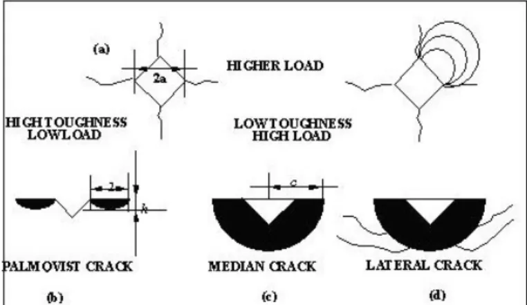
in the preferred hard tissue replacement, especially as a coating in load-bearing orthopedic implants [1,2]. In general, the major limitation for structural applications of phosphate materials is the weak mechanical properties under cyclic fatigue loading in the tissue fluid environment, and inherently brittle nature of these materials [3]. These cyclic loadings can cause the formation of local cracks leading the strength degradation of device. A fundamental understanding of such behavior may be explored through the evaluation of fracture toughness of the material using an indentation test [4,5]. Among the crack system produced by indentation, two distinct types of cracks are formed in a perpendicular plane to the indented surface, radial cracks (Palmqvist and median), while lateral cracks appear underneath and remain parallel to the surface [6,7,8]. The lateral cracks could induce surface degradation of the material following chipping and material removal [9,10]. Different types of crack propagation produced by Vickers indentation is shown in Fig. 1.
Radial cracks could not lead to considerable surface damage compared to lateral ones. From the point of surface fracture view, median cracks are more critical than Palmqvist ones produced under very low contact loads. Considering the fact that median cracks are larger than Palmqvist ones and are formed under the higher contact load, material removal from outer surface locals could be more predictable [11,12]. These conditions are encountered in the wet sliding contacts (scratch and wear circumstances) for the HA-coated implants and bulk bone substitutes before osteointegration is achieved. The interfacial fracture might be accelerated by synovial liquid diffusion from the preprothetic environment to coating-substrate interface via median cracks and other material defects
[3]. After achieving adequate osteointegration, this is the lateral cracking which would take dominant role in deterioration of coating-substrate interface. Hence, it is reasonable to distinguish between Palmqvist and median and between median and lateral crack systems [13,14].
Figure 1: Different types of crack propagation produced by Vickers indentation: a) print diagonal length, b) Palmqvist crack c) median or half-penny crack d) lateral crack.
In this study the indentation fracture toughness of a dense hydroxyapatite and Palmqvist to median crack transition were evaluated experimentally and theoretically. Transition from median to lateral cracking was also studied experimentally. Tendency for lateral cracking was evaluated by defining a realistic parameter which considered both lateral cracks and chips, afterwards.
Experimental procedure
The HA samples (produced by CRITT (Maubeuge)-France) were uniaxially pressed using HA powders (MERK). The sintering temperature and soaking time of these samples were 1270 0C
during 3 h. The cylindrical samples (15*5 mm) contained a porosity percentage of around 3%. The surface polishing by grit blasting (1200 mesh and 0.05 µm alumina) was performed before the Vickers indentation test. Vickers indentations were made with a micro-hardness tester (Lietz) in ambient air and approximately 1 min elapsed between indenting and measuring. The contact loads varied from 25 gf to 2000 gf. The indented surfaces of the samples were observed by an optical microscopy. The indentation crack profile was assessed by stepwise polishing and measuring the crack length immediately after indentation. No evidence of radial crack extension was observed, suggesting that the equilibrium radial crack length has been essentially attained quickly. Lateral crack growth was sometimes observed in the first few seconds after indenting especially throughout the chipping encountered in the high load indentions.
Result and discussion
The X-ray diffraction revealed that HA was the principal phase of samples. The hardness values were determined from the general equation of Vickers hardness. A hardness intrinsic value of 484
VHN was obtained taking into account the reciprocal length variation of the non-chipped prints.
Radial crack system
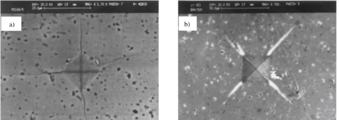
Different cracks have been identified during SEM observation of indented samples. It consisted of Palmqvist, median and lateral cracks. Fig. 2 illustrates the Palmqvist and median cracks produced in relatively low indentation loads. As reported previously, a threshold load (Pt) of around 34 gf can be
estimated from the probability for crack apparition studies. Sequential polishing revealed that for
P 150 and P 200 gf, the produced cracks were of Palmqvist and median types, respectively. The
toughness values evaluated by median system-based equations were from 0.4 to 0.5 MPam0.5, whereas they were obtained between 0.8 and 1.1 MPam0.5 according to Palmqvist system-based equations [15].
Figure 2: SEM micrographs of a) Palmqvist cracks formed at 100 gf b) Median cracks formed at 500 gf
Among the previous studies on the indentation load and crack lengths relationship, Exner [16], working on low-binder content cermets, has defined a crack resistance (w), based on the observed linear relation between the indentation load and the average Palmqvist crack length (l):
w = P/4l. (1) Ogilvy et al. [17] and Perrot [18] suggested that for high-binder content WC-Co material, this equation should be modified to:
w = (P- P0)/4l. (2)
Where P0 is a threshold indentation crack loading. Taking into account the variation of 4l and P, the value of P0 and w equal to 36 gf and 1.2 gf/ m is calculated, respectively. This threshold indentation load P0 is well near to Pt obtained from crack apparition probability.
To determine Palmqvist/median transitional load, it would be better to use just a common parameter, c for both Palmqvist and median crack systems [19]. For Palmqvist cracks, the crack length is followed by this equation:
c = l + a = (P-P0)/4w + (P/2H)0.53. (3)
Taking H, w and P0 into account as mentioned above, following relation could be obtained for Palmqvist crack system:
c = -13.67 + 0.21 P + 1.26 P00.53. (4)
Where P in gf and c in m. For median ones, crack length is formulized upon the experimental data following:
c = 1.49 P00.65. (5)
The Palmqvist to median crack transitional load (Pc) obtained by intersection of (4) and (5) relations, is 170 gf (Fig. 3). This is in consistent with the experimental determination of the transitional load by serial sectioning technique which led to a value limited between 150 and 200 gf.
Figure 3: Comparison of the crack and load data with the prediction of Palmqvist crack model and median crack regime.
Lateral crack system
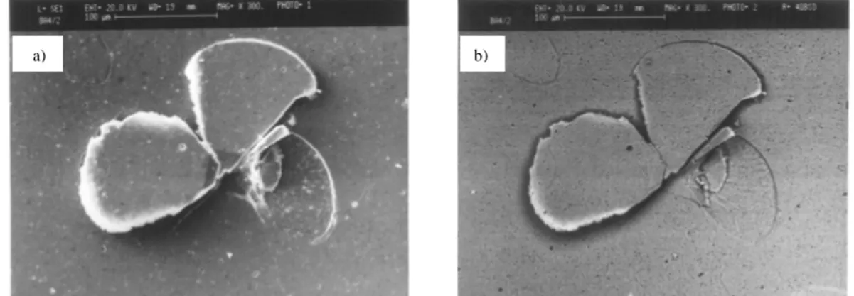
A transition load of around 200 gf was found between median and partial lateral cracking. Increasing load, more lateral cracks formed and some of ones produced the chips ejected due to continued extension of the lateral cracks toward the surface. Fig. 4 presents SEM micrograph of a print with three lateral cracking in the four quadrants.
Figure 4: SEM images of two lateral cracks and one chip formed at 1000 gf a) SE mode b) BS mode
To evaluate quantitatively the lateral cracking upon the indentation load, tendency for lateral cracking was evaluated empirically by Cook et al. [20] in the following way:
N = (2Nss + Ns) /12. (6)
With Nss is the lateral crack numbers placed in subsurface and Ns relates to the ones infiltrated in surface. In this research, the tendency for lateral cracking is modified as:
N = (Nss + Ns) /4. (7)
N value varies therefore between zero for the absence of lateral crack and 1 if all quadrants are
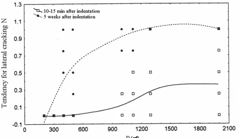
cracking. We considered Nss + Ns = 1 if two or rarely three or four cracks (at subsurface or surface) form, even partially in one quadrant. This equation could exactly imply the lateral crack numbers. Fig. 5 illustrates the calculated values of N as a function of indentation load between 10-15 min and 5 weeks after indentation. The figure clearly shows the increase of tendency for lateral cracks at high load. It could be seen that this increase is very significant at the first but a steady state situation would be established later. It is due to the exit of lateral cracks to the surface and resulting stress relaxation and crack cessation throughout the formation of chips.
The study of the number of longitudinal cracks and their growth revealed that the dense HA bodies are suspected to have surface deterioration under external stress. So, special care from local impact should be taken specially during implanting procedure. It is generally thought that these materials are not considered to be used in high load bearing applications.
Figure 5: Tendency for lateral cracking as a function of indentation load
Summary
The microindention testing led to the formation of Palmqvist/median and lateral cracks in low, mean and high indentation loads. The threshold load for primarily appearance of cracks and transition of Palmqvist to median and median to lateral cracking have been evaluated. Some of lateral cracks, especially in higher loading had tendency to emerge in surface, forming the chips. Tendency for lateral cracking was evaluated quantitatively. The evaluation of lateral cracks revealed the sensibility of HA to crack extension and surface deterioration. It should be noted that the surface degradation of biomaterials in body environment is very important in the first time following implantation. Based on the results obtained in this research, dense HA and HA-coated implants must be maintained far from impact loading particularly during surgery. It could result in local lateral cracking and subsequent surface delaminating.
References
[1] J. Faig-Marti and J. Faig-Garrober: Rev. Ortop. Traumatol. Vol. 51 (2007), p.123 [2] J. Faig-Marti and F.J. Gil-Mur: Rev. Esp. Cir. Ortop. Traumatol. Vol. 52 (2008), p. 11
[3] Ch. Benaqqa, J. Chevalier, M. Saadaoui and G. Fantozzi: Biomaterials Vol. 26 (2005), p. 6106 [4] A.G. Evans and E.A. Charls: J. Am. Ceram. Soc. Vol. 59 (1976), p.371
[5] ASTM C 1421 01b, Standard test methods for determination of fracture toughness of advanced ceramics at ambient temperature.
[6] R.F. Cook and G.M. Pharr: J. Am. Ceram. Soc. Vol 73 (1990), p. 787
[7] B.R. Lawn and D.B. Marshall, in: Fracture Mechanics of Ceramics, edited by R.C. Bradt, D.P.H. Hasselmann, and F.F. Langf , Plenum, NY(1978).
[8] M.Y. Swain and J.T. Hagan: J. Phys. D.: Appl. Phys. Vol 11 (1978), p.2091 [9] D. B. Marshall and B. R. Lawn: J. Mater. Sci. Vol 14 (1979), p. 2001 [10] A. Yonezu, B. Xu and X. Chen: Mater. Sci. Vol. 507 (2009), p. 226
[12] D.B. Marshall, B.R. Lawn, and A.G. Evans: J. Am. Ceram. Soc. Vol. 65 (1982), p. 561 [13] T. Lube: J. Eur. Ceram. Soc. Vol. 21 (2001), p. 211
[14] H. Miyazaki, H. Hyuga, Y. Yoshizawa, K. Hirao and T. Ohji: Ceram. Int. Vol. 36 (2010), p. 173
[15] A. Iost, A. Behnamghader and D. Najjar: Mesure de la tenacité de l hydroxyapatite par
indentation (MATERIAUX, France 2006).
[16] H.E. Exner: Trans. Vol. 245 (1969), p. 677
[17] I.M. Ogilvy, C.M. Perrott and J.W. Suiter: Wear Vol. 43 (1977), p. 239 [18] C. M. Perrot: Wear Vol. 47 (1978), p. 81
[19] D. K. Shetty, I. G. Wright, P. N. Mincer and A. H. Clauer: J. Mater. Sci. Vol. 20 (1985), p. 1873