NANOSCALE METALORGANIC FRAMEWORKS:
SYNTHESIS AND APPLICATION OF BIMODAL MICRO/MESO-STRUCTURE AND NANOCRYSTALS WITH CONTROLLED SIZE AND SHAPE
Thèse
MINH-HAO PHAM
Doctorat en génie chimique
Philosophiae Doctor (Ph.D.)
Québec, Canada
Résumé
Les composés à réseau moléculaire organométalliques (MOFs) ont émergé comme de nouvelles classes de matériaux hybrides organo-inorganiques avec des potentialités significatives en séparation, stockage de gaz, catalyse et support de médicaments. Ces matériaux sont formés par un processus d‟assemblage dans lequel les ions métalliques sont liés entre eux via un ligand organique, ce qui génère une surface de l‟ordre de 6500 m2g−1 et des volumes de pores supérieurs à 4.3 cm3g−1. Dans cette thèse trois différentes approches ont été développées pour la synthèse des nanocristaux MOFs à deux modes micro-mésoporeux, ainsi que des nanocristaux MOFs à taille et forme contrôlable. En plus, ces nanocristaux MOFs ont été utilisé comme un agent structurant pour la synthèse de nanocomposite hybride platine-oxyde de titane (metal-oxideTiO2PtOx) qui ont été utilisé
comme photocatalyseurs pour la production d‟hydrogène à partir de l‟eau sous la lumière visible.
Dans ce travail: (i) La première approche implique une méthode utilisant un surfactant, suivi de traitement solvo-thermale en présence d‟acide acétique pour former des nanocristaux MOFs micro-mésoporeux. L‟utilisation de surfactant non-ionique tell que F127 (EO97PO69EO97) pour induire une structure mésoporeuse provoque labilité de la
cristallisation du mur des pores de la structure MOF. Tandis que la présence de l‟acide acétique contrôle la vitesse de cristallisation du réseau MOFs pour former une mésostructure bien définie à l‟intérieur des nanocristaux MOFs. En utilisant cette approche des nanocristaux de [Cu3(BTC)2] et [Cu2(HBTB)2] de structure mésoporeuse avec des
diamètres de pores autour de 4.0 nm et des micropores intrinsèques ont été synthétisés. (ii) La méthodologie de modulation de la coordination a été développée pour contrôler la forme et la taille des nanocristaux MOFs. Des nanocubes et nanofeuilles de [Cu2(ndc)2(dabco)]n
de la structure MOFs ont été synthétisés en utilisant simultanément l‟acide acétique et la pyridine ou la pyridine uniquement, respectivement comme modulateurs sélectifs. Ces nanocristaux MOFs possèdent une cristallinité élevée et une grande capacité d‟adsorption. La morphologie a été aussi étudiée en fonction de la capacité d‟adsorption de CO2. (iii) La
MOFs, en utilisant simultanément des réactifs stabilisants et des réactifs contrôlant la déprotonation a été démontrée. Dans le cas de FeMIL-88BNH2, la molécule triblock
copolymer a été utilisée comme un réactif stabilisant en coordonnant avec le métal et contrôlant la croissance en formant des nanocristaux. L‟acide acétique joue le rôle comme un agent déprotonant des liants carboxyliques en variant sa concentration dans le milieu réactionnel, ainsi il régule la vitesse de nucléation, conduisant à aussi contrôler la taille ainsi que le rapport longueur/largeur des nanocristaux. (iv) Finalement, des nanocomposites hybrides Fe2O3TiO2PtOx de forme creuse possédant l‟activité photocatalytique
performante ont été développés en utilisant des nanocristaux FeMIL-88B composés de centres Fe3(μ3O) liés par coordination insaturée comme template solide. Ce type de
nanocomposites non seulement absorbe la lumière visible mais aussi améliore la séparation des électrons et des trous photo-générés, due à l‟épaisseur de paroi mince et les deux co-catalyseurs (Fe2O3 and PtOx) localisés sur deux opposites surfaces du creux. En
conséquence, l'efficacité en photocatalyse de ce type de nanocomposites est élevée pour la production d'H2 à partir de l'eau sous la lumière visible.
Abstract
Metalorganic frameworks (MOFs) have emerged as an important new class of porous inorganicorganic hybrid solids with the potential for a significant impact on separation, gas storage, catalysis and biomedicine. These materials are formed by assembly process in which metal ions are linked together by rigid organic ligands, which creates enormous surface areas (up to 6500 m2g−1) and high pore volumes (up to 4.3 cm3g−1). In this thesis, three different synthetic approaches have been developed to achieve bimodal micro/mesoporous MOF nanocrystals as well as nanosized MOFs with controlled size and shape. In addition, using the synthesized MOF nanocrystals as templates, a new hollow hybrid metal-oxideTiO2PtOx nanocomposite has also been prepared, and used as the
visible-light driven photocatalyst for the hydrogen production from water.
In this work, (i) the first approach involves nonionic surfactant-templated solvothermal synthesis in the presence of acetic acid toward hierarchically micro-mesoporous MOF nanocrystals. The use of a nonionic surfactant such as F127 (EO97PO69EO97) as
mesostructure template induces the ability to crystallize a MOF structure of pore wall, while the presence of acetic acid allows control of the crystallization rate of the framework to form well-defined mesostructures within the crystalline MOF nanocrystals. Using this approach, [Cu3(BTC)2] and [Cu2(HBTB)2]-based MOF nanocrystals containing mesopores
with diameter around 4.0 nm and intrinsic micropores have been successfully synthesized. (ii) Secondly, the coordination modulation methodology has been developed to control shape and size of MOF crystals at the nanoscale. Nanocubes and nanosheets of [Cu2(ndc)2(dabco)]n MOF have been rationally synthesized by using simultaneously acetic
acid and pyridine or only pyridine, respectively, as selective modulators. These MOF nanocrystals exhibit high crystallinity and high CO2 sorption capacity. Their
morphology-dependent CO2 sorption property has also been demonstrated. (iii) Thirdly, the
size-controlled hydrothermal synthesis of uniform carboxylate-based MOF nanocrystals using simultaneously stabilizing reagent and deprotonation-controlled reagent has been demonstrated. In case of FeMIL-88BNH2, the molecular triblock copolymers as
the crystal growth to form nanocrystals. Acetic acid as deprotonation-controlled reagent adjusts the deprotonation of the carboxylic linker via varying its concentration in the reaction mixture, and thus regulates the rate of nucleation, leading to tailoring the size and aspect ratio (length/width) of the nanocrystals. (iv) Finally, a new hollow hybrid metal-oxideTiO2PtOx nanocomposite as an efficient photocatalyst has been developed by using
iron-based MIL-88B nanocrystals consisting of coordinatively unsaturated Fe3(μ3O)
clusters as template. The hollow nanocomposite not only absorbs visible light, but also enhances the separation between photogenerated electrons and holes because of its thin wall and the surface separation of two distinct functional cocatalysts (Fe2O3 and PtOx) on
two different surface sides of the hollow. As a result, the efficient photoactivity of the nanocomposite photocatalysts has been found for the H2 production from water under
Table of Contents
Résumé ... iii Abstract ... v Abbreviations ... ix Acknowledgements ... xi Preface ... xiii Chapter 1 Introduction ... 1 1.1 General introduction ... 11.2 Objectives of the thesis ... 2
1.3 References ... 3
Chapter 2 Literature Review ... 5
2.1 Metalorganic frameworks ... 5
2.2 Mesoporous metal-organic frameworks ... 13
2.2.1 MOFs with mesocages ... 13
2.2.2 MOFs with mesochannels ... 21
2.2.3 Mesoporous MOFs from supramolecular templates ... 26
2.2.4 Prospective applications of MOFs involving mesopores ... 30
2.3 Nanosized metal-organic frameworks ... 33
2.3.1 Coordination modulation ... 34
2.3.2 Stabilizing reagent ... 36
2.3.3 Microemulsion ... 38
2.3.4 Synthetic parameters ... 41
2.3.5 Top-down approach ... 44
2.3.6 Potential application of MOFs involving nanosize ... 45
2.4 Photocatalytic water splitting ... 51
2.5 References ... 54
Chapter 3 Characterizations ... 65
3.1 Introduction ... 65
3.2 X-ray diffraction ... 65
3.3 Electron microscopy ... 67
3.4 X-ray photoelectron spectroscopy ... 69
3.5 Fourier transform infrared spectroscopy ... 71
3.6 Ultraviolet-visible spectroscopy ... 72
3.7 ζ-Potential analysis ... 73
3.8 Thermal analysis ... 74
3.9 Elemental analysis ... 75
3.10 Gas sorption ... 76
3.10.2 Micropore analysis ... 78
3.10.3 Size distribution of mesopores ... 80
3.11 Gas chromatography analysis ... 81
3.12 References ... 81
Chapter 4 Route to Bimodal MicroMesoporous MOF Nanocrystals ... 83
4.1 Introduction ... 89
4.2 Experimental ... 90
4.3 Results and discussion ... 91
4.4 Conclusions ... 100
4.5 Appendix ... 101
4.6 References ... 104
Chapter 5 Rational Synthesis of MOF Nanocubes and Nanosheets Using Selective Modulators and Their Morphology-Dependent Gas-Sorption Properties ... 107
5.1 Introduction ... 113
5.2 Experimental ... 115
5.3 Results and discussion ... 117
5.4 Conclusions ... 123
5.5 Appendix ... 123
5.6 References ... 126
Chapter 6 Novel Route to Size-Controlled FeMIL-88BNH2 MOF Nanocrystals 129 6.1 Introduction ... 135
6.2 Experimental ... 137
6.3 Results and discussion ... 139
6.4 Conclusions ... 150
6.5 Appendix ... 151
6.6 References ... 152
Chapter 7 Hollow Fe2O3TiO2–PtOx Nanostructure with Two Distinct Cocatalysts Embedded Separately on Two Surface Sides for Efficient Visible Light Water Splitting to Hydrogen ... 157
7.1 Introduction ... 163
7.2 Results and discussion ... 166
7.3 Conclusions ... 172
7.4 Experimental ... 172
7.5 Appendix ... 175
7.6 References ... 179
Chapter 8 Conclusions and Prospects ... 181
8.1 General conclusions ... 181
8.2 Prospects ... 182
Abbreviations
AAS Atomic absorption spectroscopy BDC 1,4-benzenedicarboxylic acid BET BrunauerEmmettTeller BJH BarrettJoynerHalenda BPDC 4,4′-biphenyldicarboxylic acid BPY 4,4′-bipyridine BTB 1,3,5-tris[4-carboxyphenyl]benzene BTC 1,3,5-benzenetricarboxylic acid BTE 4,4′,4′′-(benzene-1,3,5-triyl-tris(ethyne-2,1-diyl))tribenzoate BTTC Benzo-(1,2;3,4;5,6)-tris(thiophene-2′-carboxylate) CB Conduction band cbIM 5-chlorobenzimidazole
CTAB Cetyltrimethylammonium bromide DABCO 1,4-diaza-bicyclo[2.2.2]octane DBA 4-(dodecyloxy)benzoic acid DMF N,N-dimethylformamide DOT 2,5-dioxidoterephthalate
EDS Energy dispersive X-ray spectroscopy FTIR Fourier transform infrared spectroscopy GC Gas chromatography
H6L 1,3,5-tris (3′,5′-dicarboxy[1,1′-biphenyl]-4-yl)benzene
MOF Metalorganic framework MTN Mobil thirty-nine
NDC 1,4-naphthalenedicarboxylic acid 2,6-NDC 2,6-naphthalenedicarboxylic acid N-EtFOSA N-ethyl perfluorooctylsulfonamide NHE Normal hydrogen electrode
PCP Porous coordination polymer
PTEI 5,5'-((5'-(4-((3,5-dicarboxyphenyl)ethynyl)phenyl)-[1,1':3',1''-terphenyl]-4,4''-diyl)-bis(ethyne-2,1-diyl))diisophthalate
SAXS Small angle X-ray scattering SBU Secondary building unit SDC 4,4'-stilbenedicarboxylic acid SEM Scanning electron microscopy ST Super tetrahedron
TATAB 4,4′,4′′-s-triazine-1,3,5-triyltri-p-aminobenzoate TATB 4,4′,4′′-s-trizaine-2,4,6-triyltribenzoic
TCPP Tetrakis(4-carboxyphenyl)porphyrin TEM Transmission electron microscopy
T2DC Thieno[3,2-b]thiophene-2,5-dicarboxylate
TTEI 5,5',5''-(((benzene-1,3,5-triyltris(ethyne-2,1-diyl))tris(benzene-4,1-diyl))tris-(ethyne-2,1-diyl))triisophthalate
UV-vis Ultraviolet-visible spectroscopy VB Valence band
XPS X-ray photoelectron spectroscopy XRD X-ray diffraction
Acknowledgements
Firstly, I would like to thank Professor Trong-On Do for his excellent supervision and guidance throughout the entirety of my PhD program. I am also sincerely grateful to Professor Frédéric-Georges Fontaine at Université Laval for giving me the opportunity to work with him. I gratefully acknowledge Professor Peter McBreen at Université Laval, Professor James D. Wuest at Université de Montréal for their useful discussions.
I am very grateful for the generous and contentious help from the present and the former members of the Do group and from my other colleagues at the Département de Génie chimique of Université Laval. I wish to give thanks to all the professors and staff at the Département de Génie chimique for their great assistance and cooperation. I am also grateful to the technicians at Université Laval for providing advice and instructions to operate equipments which I have used during my PhD studies.
I am most indebted to my family, especially my wife and my lovely daughter for their unconditional love and invaluable support. I also thank my friends and acquaintances for great and impressive time during my stay in Canada.
Finally, I would like to thank Vietnam Ministry of Education and Training for a scholarship; the Natural Sciences and Engineering Research Council of Canada (NSERC), the Centre en catalyse et chimie verte (C3V, Université Laval and the Centre in Green Chemistry and Catalysis (CGCC, Québec for additional financial support.
Without all of you, it would not have been possible to realise this thesis.
Preface
This PhD thesis is built in the form of a collection of scientific papers whose first author is the submitter of this thesis. The papers have been published or submitted for publication at the time of the thesis submission.
The thesis is divided into eight chapters. The objectives of the thesis are elaborated in chapter 1 after a brief general introduction. The literature review relating to the objectives is thus presented in chapter 2, in which the background of metalorganic frameworks (MOFs), the concepts and synthetic strategies toward mesoporous MOFs as well as the prospective applications involving mesopore, the synthetic methodologies toward nanosized MOFs and the potential applications involving nanosize, the photocatalytic water splitting are reviewed. Chapter 3 outlines the background of characterizations that were applied during the performing of this PhD work.
Chapter 4 reports the nonionic surfactant-templated solvothermal method in the presence of acetic acid to achieve hierarchically porous MOF nanocrystals containing well-defined mesopores with diameter around 4.0 nm and intrinsic micropores. The writing of this chapter was supervised by Prof. Trong-On Do and Prof. Frédéric-Georges Fontaine who are the co-authors. Part of the characterizations used in this research was conducted in collaboration with Mr. Gia-Thanh Vuong who is also the co-author. This research is published in Crystal Growth & Design 2012, 12, 1008–1013.
Chapter 5 presents the rational synthesis of nanocubes and nanosheets of [Cu2(ndc)2(dabco)]n MOF by using simultaneously acetic acid and pyridine or only
pyridine, respectively, as selective modulators. The morphology-dependent CO2 sorption
property of these nanocrystals is also discussed in this chapter. The writing of this chapter was supervised by Prof. Trong-On Do and Prof. Frédéric-Georges Fontaine who are the co-authors. Part of the characterizations used in this chapter was conducted in collaboration with Mr. Gia-Thanh Vuong who is also the co-author. This chapter is published in Crystal
Chapter 6 reports the size-controlled hydrothermal approach toward uniform FeMIL-88BNH2 nanocrystals with crystal size in the range of 30150 nm in width and of 50500
nm in length by using simultaneously F127 triblock copolymer as stabilizing reagent and acetic acid as deprotonation-controlled reagent. The writing of this chapter was supervised by Prof. Trong-On Do who is the co-author. Part of the characterizations used in this research was conducted in collaboration with Mr. Gia-Thanh Vuong and Dr. Anh-Tuan Vu who are also the co-authors. This chapter is published in Langmuir 2011, 17, 15261–15267.
Chapter 7 studies the application of the prepared FeMIL-88BNH2 nanocrystals as
template to constructing a new hollow hybrid metal-oxideTiO2PtOx nanocomposite as
the efficient photocatalyst for H2 production from water under visible light irradiation. The
writing of this chapter was supervised by Prof. Trong-On Do who is the co-author. Part of the characterizations used in this research was conducted in collaboration with Mr. Cao-Thang Dinh, Mr. Gia-Thanh Vuong and Prof. Ngoc-Don Ta who are also the co-authors. This study has been submitted to a refereed journal.
Finally, Chapter 8 completes the thesis by summarizing general conclusions and prospects for future work.
Chapter 1 Introduction
1.1 General introduction
Over the past two decades, there has been an enormous progress in research on porous inorganicorganic hybrid materials that are known as metalorganic frameworks (MOFs) or porous coordination polymers (PCPs).1-4 The phrase “metalorganic framework” that was defined by Omar Yaghi et al. is now widely employed for porous crystalline structures constructed from the coordinative bonding between metal ions and rigid organic linkers.5,6 MOFs have revealed various potential applications in separation,7,8 gas storage,9,10 catalysis,11,12 sensing,13 magnetic field,14 and biomedicine.15 The prospective applications of MOFs are accounted for their stable framework,16 high porosity with enormous surface area and pore volume,17,18 the ability to systematically vary and functionalize their pore structure,19,20 and to rationally achieve pre-determined topologies with desired properties.21
Most of MOFs are microporous materials (pore size of < 2 nm) with large crystal sizes in the micrometer scale. The small apertures of the micropores and the large crystal sizes of MOFs significantly limit extensive applications of MOFs, especially in the participation of large substances such as enzymes or in applications requiring nanoscale sizes such as drug delivery.22,23 Moreover, the long micropores within MOF microcrystals also induce diffusion resistance to adsorbed guest molecules. To upgrade the performance of MOFs, several strategies to enlarge their pore size toward the mesopore regime (pore size of 250 nm)24,25 and to downsize their crystal size to the nanometer scale have thus emerged.26 The mesopores and nanosizes promote the diffusion of guest molecules through MOFs and increase accessible active sites.27 Furthermore, the mesopores also allow complex substances to be encapsulated within MOF crystals. The MOF nanocrystals exhibit various interesting features that are not observed in the bulk MOF materials such as unprecedented adsorption, processability and guest inclusion.28
Several attempts to create mesopores within MOFs have been reported. The enlargement of the organic linkers allows the expansion of the pore size of MOFs to the mesopore
regime.29 However, the obtained mesopore structures are usually collapsed upon the removal of guest molecules. In many cases, the linker extension only forms catenated MOF structures (i.e., interpenetration or interweaving of two or more identical and independent frameworks) that have smaller pores rather than their non-catenated counterparts.30 The surfactant-templated syntheses which employ the principle of the templated routes to synthesis of conventional mesoporous materials have been adopted to generate mesopores within MOF particles. However, the mesoporous MOFs have large particle size,31 or an unidentifiable crystalline structure of pore wall.32
Similarly, various approaches have been used for synthesizing nanosized MOFs. The microwave- and ultrasound-assisted syntheses produce MOF nanoparticles in a short period of time.33 The MOF nanoparticles have also been synthesized by using microemulsion systems.34 Stabilizing- and capping-reagents have been employed to suppress the crystal growth of MOFs which lead to nanosized MOFs.35 But in general, it is difficult to control the shape and size of MOF nanoparticles and the resulted nanoparticles usually appear as aggregation rather than individual nanocrystals.36
Up to date, there is a great challenge to the preparation of mesoporous MOF nanocrystals and uniform nanoscale MOFs with desired shape and size.
1.2 Objectives of the thesis
The aim of this thesis is to develop synthetic methods for preparing bimodal micro- and meso-porous MOF nanocrystals, uniform nanosized MOFs with controlled-shape and size and subsequently, the extensive application of the prepared nanosized MOFs.
The first objective is nonionic surfactant-templated solvothermal method in the presence of acetic acid to achieve hierarchically porous MOF nanocrystals containing well-defined mesopores and intrinsic micropores. The roles of the nonionic surfactant template and acetic acid in forming well-defined mesostructures as well as influencing the size and crystallinity of the hierarchically porous MOF nanoparticles have been demonstrated.
The second objective is coordination modulation methodology using simultaneously distinct selective modulators or only one selective modulator for controlling rationally the morphology of MOF nanocrystals. The effects of the nature and the concentration of selective modulators on the shape and size of MOF nanocrystals have been demonstrated. In addition, the morphology-dependent CO2 sorption property has also been illustrated.
The third objective is hydrothermal approach using simultaneously stabilizing reagent and deprotonation-controlling reagent for the preparation of uniform nanosized carboxylate-based MOFs with desired crystal sizes. The control of the stabilizing reagent and deprotonation-controlling reagent over the size of the nanosized MOFs has been demonstrated.
Finally, after the successful synthesis, the extensive application of the nanosized MOFs to preparing a new hollow hybrid nanocomposite as an efficient photocatalyst for H2
production from water under visible light irradiation is the last objective of this dissertation.
1.3 References
(1) Ferey, G. Chem. Soc. Rev. 2008, 37, 191-214.
(2) Long, J. R.; Yaghi, O. M. Chem. Soc. Rev. 2009, 38, 1213-1214.
(3) Zhou, H. C.; Long, J. R.; Yaghi, O. M. Chem. Rev. 2012, 112, 673-674.
(4) Kitagawa, S.; Kitaura, R.; Noro, S.-i. Angew. Chem. Int. Ed. 2004, 43, 2334-2375. (5) Yaghi, O. M., Li, G., Li, H. Nature 1995, 378, 703-706.
(6) Batten, S. R.; Champness, N. R.; Chen, X.-M.; Garcia-Martinez, J.; Kitagawa, S.; Öhrström, L.; O'Keeffe, M.; Suh, M. P.; Reedijk, J. CrystEngComm 2012, 14, 3001-3004.
(7) Li, J. R.; Sculley, J.; Zhou, H. C. Chem. Rev. 2012, 112, 869-932.
(8) Maes, M.; Schouteden, S.; Hirai, K.; Furukawa, S.; Kitagawa, S.; De Vos, D. E.
Langmuir 2011, 27, 9083-9087.
(9) Suh, M. P.; Park, H. J.; Prasad, T. K.; Lim, D. W. Chem. Rev. 2012, 112, 782-835. (10) Wu, H.; Gong, Q.; Olson, D. H.; Li, J. Chem. Rev. 2012, 112, 836-868.
(11) Yoon, M.; Srirambalaji, R.; Kim, K. Chem. Rev. 2012, 112, 1196-1231.
(12) Corma, A.; García, H.; Llabrés i Xamena, F. X. Chem. Rev. 2010, 110, 4606-4655. (13) Kreno, L. E.; Leong, K.; Farha, O. K.; Allendorf, M.; Van Duyne, R. P.; Hupp, J. T.
(14) Zhang, W.; Xiong, R. G. Chem. Rev. 2012, 112, 1163-1195.
(15) Horcajada, P.; Gref, R.; Baati, T.; Allan, P. K.; Maurin, G.; Couvreur, P.; Ferey, G.; Morris, R. E.; Serre, C. Chem. Rev. 2012, 112, 1232-1268.
(16) Eddaoudi, M.; Li, H.; Yaghi, O. M. J. Am. Chem. Soc. 2000, 122, 1391-1397.
(17) Furukawa, H.; Ko, N.; Go, Y. B.; Aratani, N.; Choi, S. B.; Choi, E.; Yazaydin, A. Ö.; Snurr, R. Q.; O‟Keeffe, M.; Kim, J.; Yaghi, O. M. Science 2010, 329, 424-428. (18) An, J.; Farha, O. K.; Hupp, J. T.; Pohl, E.; Yeh, J. I.; Rosi, N. L. Nat. Commun. 2012,
3, #604, 1-6.
(19) Cohen, S. M. Chem. Rev. 2011, 112, 970-1000.
(20) Tanabe, K. K.; Wang, Z.; Cohen, S. M. J. Am. Chem. Soc. 2008, 130, 8508-8517. (21) O‟Keeffe, M.; Yaghi, O. M. Chem. Rev. 2011, 112, 675-702.
(22) Deng, H.; Grunder, S.; Cordova, K. E.; Valente, C.; Furukawa, H.; Hmadeh, M.; Gándara, F.; Whalley, A. C.; Liu, Z.; Asahina, S.; Kazumori, H.; O‟Keeffe, M.; Terasaki, O.; Stoddart, J. F.; Yaghi, O. M. Science 2012, 336, 1018-1023.
(23) Horcajada, P.; Chalati, T.; Serre, C.; Gillet, B.; Sebrie, C.; Baati, T.; Eubank, J. F.; Heurtaux, D.; Clayette, P.; Kreuz, C.; Chang, J.-S.; Hwang, Y. K.; Marsaud, V.; Bories, P.-N.; Cynober, L.; Gil, S.; Ferey, G.; Couvreur, P.; Gref, R. Nat. Mater.
2010, 9, 172-178.
(24) Song, L.; Zhang, J.; Sun, L.; Xu, F.; Li, F.; Zhang, H.; Si, X.; Jiao, C.; Li, Z.; Liu, S.; Liu, Y.; Zhou, H.; Sun, D.; Du, Y.; Cao, Z.; Gabelica, Z. Energy Environ. Sci. 2012,
5, 7508-7520.
(25) Xuan, W.; Zhu, C.; Liu, Y.; Cui, Y. Chem. Soc. Rev. 2012, 41, 1677-1695.
(26) Flügel, E. A.; Ranft, A.; Haase, F.; Lotsch, B. V. J. Mater. Chem. 2012, 22, 10119-10133.
(27) Uehara, H.; Diring, S.; Furukawa, S.; Kalay, Z.; Tsotsalas, M.; Nakahama, M.; Hirai, K.; Kondo, M.; Sakata, O.; Kitagawa, S. J. Am. Chem. Soc. 2011, 133, 11932-11935. (28) Uemura, T.; Kitagawa, S. Chem. Lett. 2005, 34, 132-137.
(29) Eddaoudi, M.; Kim, J.; Rosi, N.; Vodak, D.; Wachter, J.; O'Keeffe, M.; Yaghi, O. M.
Science 2002, 295, 469-472.
(30) Farha, O. K.; Malliakas, C. D.; Kanatzidis, M. G.; Hupp, J. T. J. Am. Chem. Soc.
2009, 132, 950-952.
(31) Ma, T.-Y.; Li, H.; Deng, Q.-F.; Liu, L.; Ren, T.-Z.; Yuan, Z.-Y. Chem. Mater. 2012,
24, 2253-2255.
(32) Zhao, Y.; Zhang, J.; Han, B.; Song, J.; Li, J.; Wang, Q. Angew. Chem. Int. Ed. 2011,
50, 636-639.
(33) Li, Z.-Q.; Qiu, L.-G.; Xu, T.; Wu, Y.; Wang, W.; Wu, Z.-Y.; Jiang, X. Mater. Lett.
2009, 63, 78-80.
(34) Taylor, K. M. L.; Rieter, W. J.; Lin, W. J. Am. Chem. Soc. 2008, 130, 14358-14359. (35) Hermes, S.; Witte, T.; Hikov, T.; Zacher, D.; Bahnmüller, S.; Langstein, G.; Huber,
K.; Fischer, R. A. J. Am. Chem. Soc. 2007, 129, 5324-5325.
(36) Qiu, L. G.; Li, Z. Q.; Wu, Y.; Wang, W.; Xu, T.; Jiang, X. Chem. Commun. 2008, 3642-3644.
Chapter 2 Literature Review
2.1 Metalorganic frameworks
MOFs are porous crystalline materials with hybrid frameworks built from the linkages of metal ions with organic linkers.1-3 The functional groups of the organic linkers for coordinative bonding to the metal ions and the coordination geometry of the metal nodes (metal ions or metal-containing clusters) play a decisive role in the formation of the topologies of MOF structures. The appropriate groups are carboxylate, heterocyclic nitrogen, amine, nitrile, phosphonate and sulfonate (Figure 2.1).4-8 Among them, carboxylate group is the most commonly used functionality for designing and constructing MOF structures.9,10 Multitopic linkers (i.e., containing two or more functional groups) with rigid carbon backbones favor prominently in the quest for stable and robust frameworks that retain MOF integrity in the absence of guest molecules. The rigid carbon backbones are usually aromatic chains or alkenyl chains with double bonds. Metalloligands are also used as linkers for the construction of MOFs.11-16 Furthermore, the linkers can be flexible organic molecules, but in some cases they tend to give MOF structures in the form of dense packing or interpenetration.17-19
Ditopic linkers
1,4-benzenedicarboxylic acid 1,4-diaza-bicyclo[2.2.2]octane 1,5-naphthalenedisulfonic acid
Tritopic linkers
1,3,5-benzenetricarboxylic acid 2,4,6-tris(4-pyridyl)-1,3,5-triazine 1,3,5-benzenetriphosphonic acid
Tetratopic linkers
1,3,5,7-adamantanetetrabenzoic acid Tetrakis[4-(carboxyphenyl)oxamethyl]methane
1,3,5,7-tetrakis(4-phosphonophenyl)adamantine Tetrakis(4-cyanophenyl)methane
Figure 2.1 Multitopic organic linkers for MOF construction.4-16
The metal ions constructing MOF structures possess several coordination numbers. The first row transition metal ions such as Cr3+, Fe3+, Cu2+ and Zn2+ are widely used for constructing MOFs.10,20 The coordination of the functional groups of organic linkers to the metal ions often generates polyatomic clusters containing two or more metal atoms,
so-called secondary building units (SBUs). The SBUs give points of extension where they connect to the rigid carbon backbones of the organic linkers to form porous structures. The geometry of the SBUs is determined by the coordination number, coordination geometry of the metal ions and the nature of thefunctional groups. The variety of SBU geometries with different numbers of points of extension has been observed in MOF structures.10,21 However, the metal-containing SBUs are not isolatable entities, and so it is essential to establish exact chemical conditions that will yield a specific SBU in situ.8
Octahedron (6 points) Trigonal prism (6 point) Square paddle-wheel (4 points)
Triangle (3 points) Square pyramid (5 points) Cube (8 points)
Figure 2.2 Geometry and number of points of extension of representative SBUs. Metal: polyhedral; C: black; O: red; Heteroatom: green, cyan. Reproduced with the permission of The Royal Society of Chemistry.10
The most common SBUs are clusters of metal ions and carboxylate groups. The typical examples are octahedral, trigonal prism and square paddle-wheel SBUs (Figure 2.2).10 The octahedral SBU with the formula of M4O(COO)6 consists of a central bridging O atom
bonding to four tetrahedral metal atoms to form a tetrahedral M4O unit; and six carboxylate
groups connecting the edges of the tetrahedra. The six points of extension (i.e., six carbon atoms of the carboxylate groups) are at the vertices of the octahedron. This cluster is found for Zn, Co and Be. In case of trigonal prism SBU with the formula of M3O(COO)6, three
metal atoms is bridged by two carboxylate groups. Each metal ion coordinates to a terminal ligand such as solvent or anion. The six points of extension locate at the vertices of the trigonal prism. This SBU is observed for several metals such as Cr, Fe and Al. In the square paddle-wheel SBU, two metal ions are bridged by four carboxylate groups and each metal ion is coordinated by a terminal ligand on the apical position. This structure is represented by Cu2(COO)4 SBU.
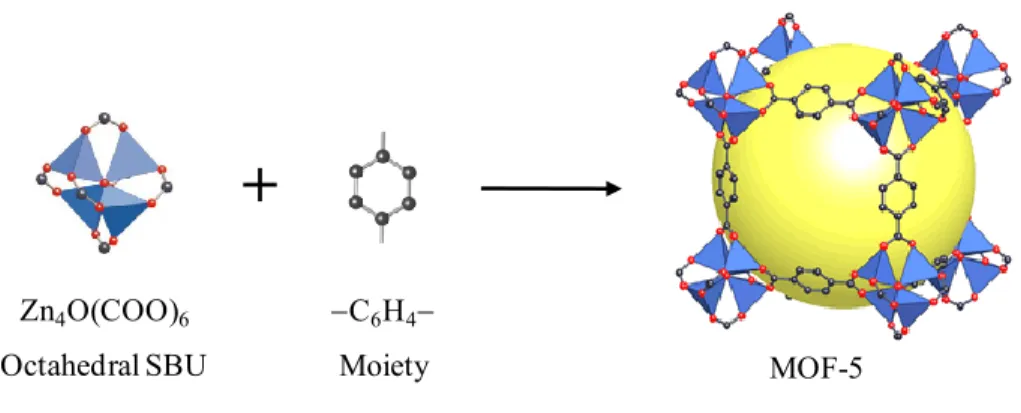
The connection between the metal-containing SBUs via the carbon backbones of organic linkers forms porous crystalline structures of MOFs.22 The judicious use of appropriately shaped SBUs and rigid organic linkers results in the formation of pre-determined MOF topologies.23,24 The well-known example is the design and preparation of MOF-5 framework.25 In this framework, the zinc-carboxylate SBUs with six points of extension in octahedral geometries connect to phenyl rings of 1,4-benzenedicarboxylic (BDC) acids to form porous cubic structure (Figure 2.3).
Figure 2.3 MOF-5 built from the connection of the octahedral SBUs with BDC acids. C: gray; O: red; Zn: blue tetrahedral. All hydrogen atoms are omitted for clarity. The large yellow sphere represents the largest van der Waals sphere that fits in the cavity of the framework. Reproduced with the permission of Nature Publishing Group.25
In principle, an almost unlimited number of MOFs can be constructed due to a great diversity of organic linkers and metal-containing SBUs. The connection of a specific SBU with different organic linkers and vice versa leads to MOF structures with different
+
MOF-5 Zn4O(COO)6 Octahedral SBU C6H4 Moietytopologies. The illustrative example is shown in Figure 2.4. The connection of trigonal prism SBUs with different organic linkers, either BDC acids as ditopic linker or 1,3,5-benzenetricarboxylic (BTC) acids as tritopic linker, creates the different topologies of MIL-88B and MIL-100 (MIL standing for Materials of the Institute Lavoisier).26,27 In the other hand, the connection of the same tritopic BTC linkers with dicopper square paddle-wheel SBUs instead of trigonal prism SBUs results in HKUST-1 topology (HKUST standing for Hong Kong University of Science and Technology).28 As a result, the features of the resulted frameworks such as pore structure, porosity, rigidity of the frameworks and physicochemical properties are also different.
Figure 2.4 Topologies of MOFs from the different connections between SBUs and organic linkers. C: gray; O: red, Cu: cyan; metal such as Cr, Fe: green. Reproduced with the permission of The Royal Society of Chemistry, Willey and Elsevier.26-28
Functional groups such as NH2, NO2, SO3H, CN, OH, OCxHy, CxHy, CF3,
COOH, azide (N3) and halogens have been attached on organic linkers, commonly
aromatic linkers, to generate functionalized MOFs.29-38 The functionalized MOFs are often
MIL-88B MIL-100 HKUST-1
monofunctional structures containing a single type of functional groups. The introduction of functional groups creates isoreticular MOFs with the same network, such as IRMOF-n (n = 2 5) possessing the network of IRMOF-1 (or MOF-5).33 The functional groups can improve the stability and tailor the property of the parent structures for interesting applications. Multifunctional MOFs containing two or more distinct chemical functionalities have also been fabricated by integrating several organic linkers into a single platform.39-41 The multifunctional MOFs provide integrated properties that their monofunctional counterparts can not achieve.42
MOF structures can be built from two or more types of organic linkers instead of one type of linker.43-46 In the example to [M2(dicarboxylate)2(N ligand)]n MOFs, the three dimension
structure of [Cu2(ndc)2(dabco)]n MOF is built from the connection of dicopper square
paddle-wheel SBUs with two distinct linkers, including 1,4-naphthalene dicarboxylic (ndc) acid and 1,4-diaza-bicyclo[2.2.2]octane (dabco).47 In this structure, NDC molecules connect with dicopper square paddle-wheel SBUs to form two dimension square lattices that are connected together by dabco molecules at the lattice points to form the porous structure (Figure 2.5).
Figure 2.5 Structure of [Cu2(ndc)2(dabco)]n. Cu: blue; N: green; O: red; and C: gray. All
hydrogen atoms are omitted for clarity. Reproduced with the permission of Elsevier.48
The crystalline structures of MOFs are normally quite rigid. However, the reversible structural variation with retained topology can occur in various MOFs under external stimuli. Such variation of the flexible frameworks is usually called “breathing effect”.49-51
The breathing effect is activated by the presence of inserted guests such as water, solvents and gases. The breathing amplitude is governed by the host-guest interaction and the flexibility of MOF skeleton. The structural variation results in a dynamic change in the pore size and shape. During the breathing, the position of the Bragg peaks in the X-ray diffraction powder pattern shifts as a result of the change of the unit cell parameters.
The large breathing effect has been found in some carboxylate-based MOFs such as 88 structures (88A constructed from fumaric acid, 88B from BDC acid, MIL-88C from 2,6-naphthalenedicarboxylic (2,6-NDC) acid and MIL-88D from 4,4′-biphenyldicarboxylic (BPDC) acid),27,52,53 MIL-53,54-58 MIL-89,59 DUT-8,60 MCF-18,61 and DMOF-1.62,63 The possible breathing of a carboxylate-based MOF occurs only if structural rules are all satisfied.49 The rules include the existence of a mirror plane in the SBU with the carboxylates in symmetrical positions toward them, for example in the square paddle-wheel dimers of DMOF-1 and the trigonal prism trimers of MIL-88; ditopic linker; and the absence of rigid odd cycles. Therefore, at variance to 88, 53 and DMOF-1; MIL-101 owning pentagonal windows,64 MOF-5 consists of tetragonal SBUs without the mirror planes,25 and HKUST-1 constructed from tritopic linkers28 do not breath. Moreover, it seems that the ratio of number of carbons of the carboxylates surrounding the SBU to number of metal atoms within the SBU must be greater than or equal to 2 for such breathing effect.
In the illustrative example based on MIL-88B,65 the topology has large cages with a trigonal bipyramid shape. The vertices of the bipyramid are occupied by trigonal prism SBUs. The ditopic linkers are on the edges of the bipyramid and there is no link in the equatorial plane of the bipyramind. The SBUs can rotate around the knee cap OO axes of the carboxylates and the OOCCOO axes of the linkers (Figure 2.6, left). These rotations accompanying with the absence of rigid linkages between the equatorial SBUs can induce a change in the distance between the equatorial SBUs under external stimuli, leading to breathing effect. Indeed, the as-synthesized form of MIL-88B contains a few solvent molecules in the bipyramid cage. When the solvents are removed from the cage (dry form), the length between the two non-equatorial SBUs increases whereas the distance between
the equatorial SBUs decreases. In contrast, the bipyramid flattens and its volume increases if the solvents are exchanged into the cage (open form) (Figure 2.6, right). The expansion of the cell volume between the dry and open forms of MIL-88B can be over 125 %.
Figure 2.6 (Left) One edge of the trigonal bipyramid and the possibility of rotation around the knee cap OO axes (blue lines) with the senses of the rotations (blue arrows) of the whole SBUs (green arrows) in MIL-88B. White arrow shows possible rotations around the OOCCOO axis of the linker. (Right) Evolution of the bipyramid (top) and correlative evolution of the structure along [001] (bottom) during breathing. Reproduced with the permission of Science and The Royal Society of Chemistry.65
The organic linkers and metal-containing SBUs impart the characteristics of MOFs such as high porosity with large surface area and pore volume,66,67 high stability,68 and the ability to tailor the pore cavity environment.69,70 The extraordinary degree of variability for both
organic linkers and metal-containing SBUs leads to tunable properties that make MOFs of interest for potential applications such as gas storage,71-76 separation,77-79 catalysis,80-82 sensing,83-86 biomedicine,87-89 and proton conductivity.90-94 Moreover, the post-synthetic modifications also allow the manipulation of the physical and chemical properties of a given MOF in a controllable manner.69,95-99 Therefore, the design and use of organic linkers as well as the selection of metals focus on MOF structures suitable for their targeted applications.6 For instance, the incorporation of electron-rich functional groups on the
9.6 Å 15.6 Å
19.1 Å 15.9 Å
Dry As-synthesised Open
V=3400 Å3
organic linkers provides high affinity with CO2 gas which promotes preferential CO2
adsorption and separation,34,100,101 while the attachment of achiral functionalities offers catalytic activity for enantioselective reactions.81 Similarly, coordinatively unsaturated metal ions in square paddle-wheel or trigonal prism SBUs after the removal of axial terminal ligands act as Lewis acid sites that have high affinity with various guests such as adsorbates,102-104 catalytic organic molecules,105,106 porosity-customizing agents,107 and reagents generating proton conductivity.108 A number of MOFs built from lanthanide metals have luminescence that makes them ideal for sensing,109,110 while various MOFs constructed from paramagnetic metals have magnetism suitable for magnetic applications.111-113
2.2 Mesoporous metal-organic frameworks
One of the most important properties of MOFs is porosity with large surface area and high pore volume. The IUPAC classifies porous solids into three categories according to their pore size: microporous (d < 2 nm), mesoporous (2 nm d 50 nm) and macroporous (d > 50 nm) materials. Therefore, most of the reported porous MOFs are microporous and only a small fraction of MOFs are mesoporous (Table 2.1). The concept of the mesoporous MOFs refers not only to structures possessing large cavities and/or channels with diameters over 2 nm but also to MOF particles owning mesopore systems derived from supramolecular templates which are similar to those of conventional mesoporous materials.
2.2.1 MOFs with mesocages
A number of MOFs having large cavities within the range of 2 50 nm (so-called mesocages) have been prepared from one type of organic linker or the mixture of different linkers in coordination with metal-containing SBUs that possess different geometric shapes. One of these MOF structures is MIL-101.64 The structure of MIL-101 consists of trigonal prism SBUs and ditopic linkers. The connection between the SBUs and the ditopic BDC linkers constructs microporous super tetrahedron (ST) (Figure 2.7). The four vertices of the ST are occupied by the SBUs while the ditopic linkers locate at the six edges of the ST. The
STs are computationally assembled through their vertices to produce an open framework with the Mobil thirty-nine (MTN) zeotype topology. In this assembly, the STs serve as tetrahedral TO4 units of the MTN zeotype. MIL-101 structure has two types of mesocages
with internal diameters of 29 Å and 34 Å. The small mesocage constructed by 20 STs has 12 pentagonal windows while the large mesocage defined by 28 STs has 12 pentagonal and 4 hexagonal windows. Although these cages are mesopores, the apertures of the windows in MIL-101 are limited within the size range of micropore at 12 Å for the pentagonal windows and 14.7 16 Å for the hexagonal windows.
The extension of the length of the ditopic linker creates larger mesocages within MIL-101 structure. Ferey et al. used 2,6-NDC acid that has a longer carbon backbone rather than that of BDC acid for the preparation of MIL-101_NDC material.114 Similar to MIL-101 based on BDC acid, MIL-101_NDC is also constructed from ST subunits and has the MTN zeotype structure. However, the ST of MIL-101_NDC material (about 10.2 Å) is larger than that of MIL-101 (about 8.6 Å) because of the longer carbon backbone of 2,6-NDC acid. This results in two larger mesocages of MIL-101_NDC with internal diameters of 39 Å and 46 Å. The pentagonal and hexagonal windows have free diameters of approximately 13.5 Å and 18.2 20.3 Å, respectively.
Table 2.1 The structural features of representative mesoporous MOFs.
MOFs Linkers Mesoporous structure (Å) Apertures (Å) Ref. Cages Channels Templates
MIL-101 BDC 29 and 34 12.0 and 14.7 64
MIL-101_NDC 2,6-NDC 39 and 46 13.5 and 18.2 114
MIL-100 BTC 25 and 29 4.8 and 8.6 26
Tb-mesoMOF TATB 39 and 47 13.0 and 17.0 115
UMCM-2 T2DC and BTB 26 32 116
DUT-6/MOF-205 NDC and BTB 2530 117,66
MOF-210 BTE and BPDC 26.9 48.3 66
PCN-53 BTTC 22.2 16 118 PCN-68 PTEI 23.2 119 PCN-610/NU-100 TTEI 27 119, 120 NOTT-119 H6L 25 19 121 ZIF-95 cbIM 24 3.65 122 ZIF-100 cbIM 35.6 3.35 122
Table 2.1 (Continuous)
MOFs Linkers Mesoporous structure (Å) Apertures (Å) Ref. Cages Channels Templates
Bio-MOF-1 Adenine and BPDC mesocage 28 (3-D) 67
IRMOF-16 TPDC 28.8 (3-D) 33 mesoMOF-1 TATAB 22.5 26.1 (3-D) 123 CYCU-3 SDC 28.3 31.1 (1-D) 124 JUC-48 BPDC 21.1 24.9 (1-D) 125 IRMOF-74 DOT 14 98 (1-D) 126 PCN-222 TCPP 37 (1-D) 127 UMCM-1 BTB and BDC 27 32 (1-D) 128 MMOF-n Disulfonate 61 75 F127 129 Zn-BDC BDC 30 N-EtFOSA 130 Cu3(BTC)2 BTC 25 N-EtFOSA 131 Cu3(BTC)2 BTC 38 310 CTAB/TMB 132 MOF-5 BDC > 100 DBA 133
Figure 2.7 Architecture of the mesocages and windows in MIL-101. In the scheme of the MTN zeotype structure, the small and large mesocages are presented in green and red, respectively. Metal octahedral: green; O: red; C: blue. Reproduced with the permission of Science.64
By using tritopic BTC linker instead of ditopic BDC linker in coordination with the trigonal prism SBU, mesoporous MIL-100 with the same MTN zeotype topology was previously prepared by Ferey et al. in 2004.26 The structure of MIL-100 is also constructed from tetrahedral ST subunits, in which four BTC linkers span four faces of the ST while the vertices of the ST are still occupied by the trigonal prism SBUs (Figure 2.4). Each BTC connects three trigonal prism SBUs via its three carboxylate groups and the phenyl ring of BTC occupies the center of the triangle face obtained by joining the three SBUs. Therefore, the ST in MIL-100 has smaller diameter rather than its counterpart in MIL-101, at 6.6 Å
and 8.6 Å, respectively. As a result, the mesocages of MIL-100 have smaller diameters at 25 Å for the small cage and 29 Å for the large cage. Similar to MIL-101 material, the windows of MIL-100 have small diameters at 4.8 5.8 Å for the pentagonal windows and 8.6 8.6 Å for the hexagonal windows.
Using a longer tritopic linker, 4,4′,4′′-s-trizaine-2,4,6-triyltribenzoic acid (TATB), Kim et
al. prepared a mesoporous MOF from Tb3+ ions (namely Tb-mesoMOF) possessing the same MTN zeotype topology as that of MIL-100 and MIL-101.115 In this case, the tritopic TATB linkers connect trigonal-planar Tb4 clusters to produce STs (Figure 2.8). Each face
of the ST is spanned by the pair of TATB linkers that stack with each other. The outer TATB of this pair joins three peripheral Tb3+ ions in a bidentate fashion while the inner TATB links three central Tb3+ ions and other three peripheral Tb3+ ions in a bi-monodentate fashion. Because the carbon backbone of TATB is elongated by three additional phenyl rings when compared to that of BTC and BDC, the mesocages in Tb-mesoMOF are larger than those of MIL-100 and MIL-101 as the result of the increase in the dimension of the STs. The internal diameters of the mesocages are 39 Å and 47 Å. Although the mesocages are larger, the apertures of the windows are also limited within micropore regime at 13 Å for five-membered rings and 17 Å for six-membered rings.
Figure 2.8 The ST consisting of TATB acids and trigonal-planar Tb4 clusters and the
topology of Tb-mesoMOF. Each blue truncated tetrahedron on the topology represents one ST. C: gray; O: red; N: blue; Tb: turquoise. Reproduced with the permission of Wiley InterScience and American Chemical Society.115
TATB Super Tetrahedron Topology
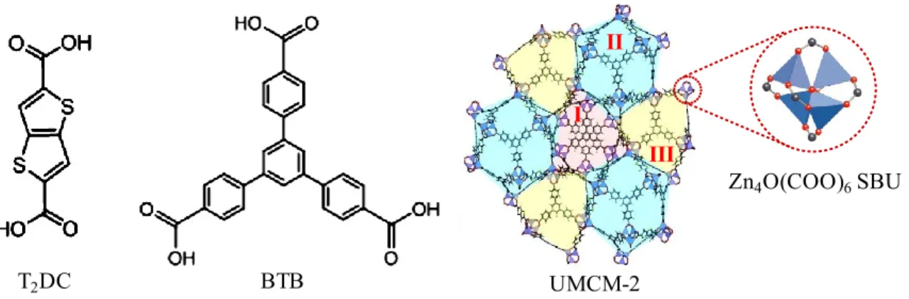
Besides one type of linkers, some MOFs having mesocages are constructed from the mixture of different types of linkers. Indeed, the coordination of ditopic thieno[3,2-b]thiophene-2,5-dicarboxylate (T2DC) and tritopic 1,3,5-tris(4-carboxyphenyl)benzene
(BTB) with zinc in the form of octahedral Zn4O(COO)6 SBUs produces mesoporous
UMCM-2 MOF (UMCM standing for University of Michigan Crystalline Material).116 UMCM-2 structure has a mesocage with internal dimension of approximately 26 32 Å and two different microporous cages (Figure 2.9).
Figure 2.9 Structure of UMCM-2. The cage II (in cyan) is mesoporous while the cages I (in red) and case III (in yellow) are microporous. Reproduced with the permission of American Chemical Society.116
DUT-6 (DUT standing for Dresden University of Technology) with mesocages is also built from the mixture of ditopic 2,6-NDC linker and tritopic BTB linker which connect to octahedral Zn4O(COO)6 SBUs (Figure 2.10).117 The carboxylate groups in the SBU come
from four BTB linkers in a square planar arrangement and two 2,6-NDC linkers. The MOF structure provides dodecahedral mesocages with diameter of 25 – 30 Å which are built from twelve Zn4O(COO)6 SBUs, six 2,6-NDC linkers and eight BTB linkers. The second
type of cage in DUT-6 is constructed from four Zn4O(COO)6 SBUs, two 2,6-NDC linkers
and four BTB linkers. These smaller cages are arranged to connect the mesocages to form a periodic space filling. This MOF structure was independently reported as MOF-205 by Yaghi et al. in 2010.66 T2DC BTB UMCM-2 II III I Zn4O(COO)6SBU
Figure 2.10 Structure of mesoporous DUT-6. Reproduced with the permission of Wiley InterScience.117
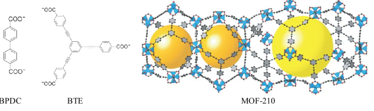
Recently, MOF-210 with mesocages has been prepared from the mixture of ditopic BPDC and tritopic 4,4′,4′′-(benzene-1,3,5-triyl-tris(ethyne-2,1-diyl))tribenzoate (BTE) linkers (Figure 2.11).66 The largest mesocage with a dimension of 26.9 48.3 Å in MOF-210 consists of eighteen Zn4O(COO)6 SBUs, fourteen BTE and six BPDC linkers. The material
exhibits an enormous BET surface area of 6240 m2g-1 and a total carbon dioxide storage capacity of 2870 mg.g-1.
Figure 2.11 Structure of MOF-210. The yellow and orange spheres indicate spaces in the cages. Reproduced with the permission of Science.66
Although the MOFs possessing mesocages exhibit mesoporous features, their small apertures of the windows within the micropore range below 20 Å limit the access of large substances to the mesocages. The increase of the apertures to the mesopore range is still a great challenge.
Mesocage Small cage Topology
2.2.2 MOFs with mesochannels
2.2.2.1 Three dimension mesochannels
The common strategy to enlarge the channels of MOFs toward the mesopore range of 2 50 nm (so-called mesochannels) is the extension of organic linkers. The linker extension takes the advantage of the increase of the channel size corresponding to the length of the linker. However, the linker expansion can result in catenated structures with small channels.134 Moreover, MOFs built from long linkers can be collapsed upon guest removal.135 Therefore, the construction of a MOF with 3D mesochannels from a given network topology via the extension of the linker should inhibit the catenation and collapse.84,134
Figure 2.12 Structure of non-catenated IRMOF-16, interpenetrated IRMOF-15 isomer and mesoMOF-1. The colored spheres represent the void inside the cavities. Reproduced with the permission of Science, American Chemical Society and Elsevier.33, 123
TPDC Zn4O(COO)6
+
IRMOF-16 TATAB+
Cu2(COO)4 mesoMOF-1 IRMOF-15 OctahedronThe typical non-catenated MOF with 3D mesochannels prepared via the extension of linker is IRMOF-16.33 The MOF has the same topology of MOF-5 (IRMOF-1), in which Zn4O(COO)6 octahedral SBUs connect to the aromatic backbones of ditopic carboxylate
linkers to form cubic network (Figure 2.12, top). In MOF-5, the carbon backbone has one phenyl ring, giving micropores with the free- and fixed diameters of 11.2 Å and 18.5 Å, respectively. In contrast, the carbon backbone in IRMOF-16 is elongated with two additional phenyl rings, generating mesochannels with the free- and fixed diameters of 19.1 Å and 28.8 Å, respectively. IRMOF-16 should be synthesized under dilute conditions to avoid catenation that results in the interpenetrated structure of IRMOF-15 isomer with smaller micropores at 8.1 Å and 12.8 Å in free- and fixed diameters, respectively.
Zhou et al. prepared mesoMOF-1 with 3D mesochannels by the extention of tritopic carboxylate linkers.123 MesoMOF-1 with the same topology of HKUST-1 is built from dicopper square paddle wheel SBUs and tritopic 4,4′,4′′-s-triazine-1,3,5-triyltri-p-aminobenzoate (TATAB) linkers (Figure 2.12, bottom). Although TATAB has a longer carbon backbone rather than BTC in HKUST-1, mesoMOF-1 has non-interpenetrated structure because of the nonplanarity of TATAB linkers. In mesoMOF-1 structure, each Cu2(COO)4 SBU connects four TATAB linkers, and each TATAB links three SBUs to
form an octahedron, in which all six vertices are occupied by the SBUs, and four of the eight faces are spanned by TATAB linkers. Eight such octahedra occupy the eight vertices of a cube to form a cuboctahedron through corner sharing. These cuboctahedra propagate to an open framework with 3D mesochannels of 22.5 26.1 Å in diameter.
Recently, An et al. have reported an alternative strategy for constructing mesoporous MOFs which addresses the size of the vertex rather than the length of organic linkers. They used large zinc-adeninate building units (ZABUs) as vertices to construct bio-MOF-100 (Figure 2.13).67 In bio-MOF-100, each ZABU consists of eight Zn2+ cations interconnected by four adeninates and two µoxo groups. Monodentate BPDCs occupy the remaining coordination sites on each tetrahedral Zn2+ cation. The ZABU is connected to four adjacent ZABUs via twelve BPDC linkers to generate open structure with mesocages and 3D mesochannels with
a diameter of 28 Å along the axes. This MOF structure exhibits the largest pore volume reported to date, up to 4.3 cm3g−1.
Figure 2.13 Structure of bio-MOF-100: ZABU can be treated as a distorted truncated tetrahedron. Each truncated tetrahedron connects four adjacent tetrahedra to generate open framework. Zn: dark blue tetrahedra; C: grey spheres; O: red spheres; N: blue spheres. Reproduced with the permission of Nature Publishing Group.67
2.2.2.2 One dimension channels
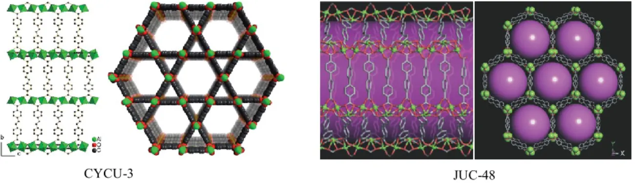
The construction of infinite rod-shaped SBUs has been employed to generate MOFs with 1D mesochannels such as CYCU-3 (CYCU standing for Chung-Yuan Christian University),124 and JUC-48 (JUC standing for Jilin University China) materials (Figure 2.14).125 In CYCU-3 structure, each octahedral Al3+ ion binds to four oxygen atoms from four carboxylate groups of 4,4'-stilbenedicarboxylic acids (SDC) and two oxygen atoms from the bridged hydroxide groups. The octahedral AlO6 units form corner-shared 1D
SBUs that are linked together by the SDC linkers to generate two types of 1D channels, including hexagonal mesochannels with the cross-section size of approximately 28.3 31.1 Å and triangular micropores with the pore size of 14.4 Å. Similarly, JUC-48 is constructed from rod-shaped Cd2+ carboxylate SBUs. These SBUs are interconnected through the biphenyl chains of BPDC linkers to generate a non-interpenetrated network with 1D hexagonal mesochannels of 24.5 27.9 Å.
Large cage Topology
Figure 2.14 Structures of CYCU-3 and JUC-48. Reproduced with the permission of The Royal Society of Chemistry and Wiley InterScience.124, 125
Figure 2.15 Structure of the series of nine IRMOF-74-I to XI. C: gray; O: red; metal: blue. Reproduced with the permission of Science.126
The construction of infinite rod-shaped SBUs in combination with the extension of organic linkers has been used for enlarging 1D channels of MOFs. The strategy has been employed for the systematic expansion of MOF-74 from its original link of one phenyl ring (I) (2,5-dioxidoterephthalate, DOT) to eleven (XI), which affords an isoreticular series of nine MOF-74 structures (termed IRMOF-74-I to XI) (Figure 2.15).126 The topology of IRMOF-74 is built from infinite rod-shaped SBUs. The SBU is in a hexagonal arrangement joined
CYCU-3 JUC-48
along the short and long axes by metal-oxygen bonds and organic DOT links, respectively. The formation of the short axis is ensured by the coordination of 5-coordinate metal atoms to the carboxylic and the ortho-positioned hydroxyl functionalities of DOT links. DOT links (long axes) join the infinite rod-shaped SBUs to make IRMOF-74 structure with 1D hexagonal channels. Upon the elongation of DOT links, the nine members of this series with non-interpenetrated robust structures have hexagonal channels in the range of 14 98 Å in size.
In a different assembly, the structure of PCN-222 (PCN standing for porous coordination network) containing 1D mesochannels is built from Zr6 clusters instead of infinite
rod-shaped SBUs (Figure 2.16).127 In this structure, only eight edges of the Zr6 octahedron are
bridged by the carboxylates from square planar tetrakis(4-carboxyphenyl)porphyrin (TCPP) linkers, while the remaining positions are occupied by terminal hydroxy groups. Therefore, the framework of PCN-222 can be viewed as zirconium-carboxylate layers in the ab plane which are pillared by TCPP linkers along the c axis. PCN-222 provides 1D hexagonal mesochannels with a diameter of 37 Å. Moreover, the isomers of PCN-222 with uncoordinated porphyrin or metalloporphyrins including Fe, Mn, Co, Ni, Cu, and Zn can be produced, which affords a new series of PCN-222.
Figure 2.16 Structure of PCN-222. Zr: black; C: gray; O: red; N: blue; metal in porphyrin: orange. Reproduced with the permission of Wiley InterScience.127
Zr
6octahedron
TCPP
Topology
Mesochannel
The combination of different types of organic linkers has been employed for the construction of MOFs with 1D mesochannels. Koh et al. have synthesized mesoporous UMCM-1 by combining ditopic BDC with tritopic BTB in the presence of zinc cations (Figure 2.17).128 Each octahedral Zn4O SBU in UMCM-1 is coordinated by two BDC
linkers and four BTB linkers. This structure generates micropous cages and 1D hexagonal mesochannels with a diameter of 27 32 Å.
Figure 2.17 Structure of UMCM-1. Reproduced with the permission of Wiley InterScience.128
2.2.3 Mesoporous MOFs from supramolecular templates
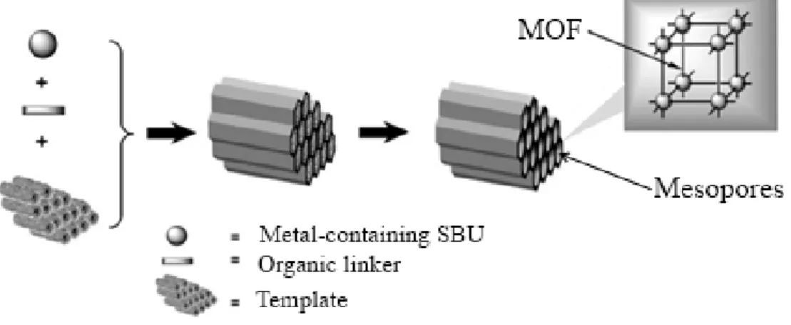
The template-assisted synthetic approach has been adopted to prepare mesoporous MOFs. Similar to traditional mesoporous materials, the co-assembly approach uses structure-directing agents (supramolecular templates) for generating mesostructures (Figure 2.18). For the co-assembly into mesostructures and the growth of MOF directed by the templates, the interaction between MOF precursors and the supramolecular templates with considerable strength is essential. Otherwise, macroscopic phase segregation may take place, and the MOF will crystallize by itself despite the templates.136
Figure 2.18 Schematic illustration of the synthesis of mesoporous MOFs using supramolecular templates. Reproduced with the permission of Wiley InterScience.132
2.2.3.1 Non-ionic templates
Nonionic triblock copolymers have been used as supramolecular templates for fabricating mesoporous MOFs. Ma et al. used the surfactant F127-induced co-assembly for producing MOFs with order mesopore structures from two disulfonic linkers (1,5-naphthalenedisulfonic and ethanedisulfonic acids) and different metal ions (Cd2+, La3+, Cu2+ and Sr2+).129 The MOF walls of the mesopores are built from the crystalline frameworks of metal-disulfonate. Since the easy coordination of the sulfonate groups with the metal ions facilitating the formation of large MOF crystals rather than the co-assembly between the surfactant and the MOF precursors into mesostructures, the crown ether 1,10-diaza-18-crown-6 was added to control the release of the metal ions, which slowed down the coordination rate between the metal centers and the sulfonate claws.
In such acidic synthesis system, the PEO segments of the triblock copolymer F127 (PEOPPOPEO) were protonated, producing positively charged head groups. The positively charged surfactants (SoH+), the disulfonate anions (X−) and the metal cations (I+) assembled together via (SoH+)X−I+ mechanism to form ordered hexagonal mesostructures. The propagation of the metal-disulfonate coordination (X−I+)formed the crystalline MOF walls of the mesostructures. After the removal of the F127 surfactant by acidic ethanol
extraction, the obtained MOF particles contained mesopores with the pore diameters in the range from 6.1 to 7.5 nm.
Nonionic N-ethyl perfluorooctylsulfonamide (N-EtFOSA) has also been used as supramolecular templates for synthesizing hierarchically micro- and mesoporous MOF particles. N-EtFOSA molecules self-assemble into cylindrical micelles, in which the fluorocarbon tails direct toward the inside of the micelles. By using N-EtFOSA, Zhao et al. synthesized MOF nanospheres with well-ordered hexagonal mesopores from Zn2+ ions and BDC acids in an IL/SCCO2/surfactant emulsion system (IL =
1,1,3,3-tetramethylguanidinium acetate ionic liquid and SCCO2 = supercritical CO2).130 Because of
the strong interaction of the CO2 molecules with the fluorocarbon tails, the CO2 molecules
existed as the core of the micelles. The coordination of Zn2+ ions with BDC linkers in the IL generated the microporous MOF walls. After the removal of the IL, CO2, and the
surfactant, uniform MOF nanospheres with well-ordered mesopores and microporous walls were achieved. The sizes of micropores, mesopores and the wall thickness were about 0.7, 3.0 and 2.5 nm, respectively.
Recently, Peng et al. have used N-EtFOSA as nonionic template for synthesizing mesoporous MOF nanoplates based on HKUST-1 structure in the IL solution.131 In this case, the surfactant has a dual role in the formation of the mesoporous MOF nanoplates. On the one hand, the surfactant molecules play the role of a template in the mesopore formation. On the other hand, the surfactant can selectively adsorb onto the crystallographic planes of the MOF, thus serving as a directing agent and kinetically controlling the anisotropic growth of the MOF. In the process, Cu2+ ions in the IL first react with the deprotonated BTC to form nanosized framework building blocks. The nanosized building blocks then assemble with N-EtFOSA molecules to form mesostructured MOF particles. The removal of the surfactant from the mesostructured particles gives mesopores with the diameter around 2.5 nm.
2.2.3.2 Cationic templates
In addition to nonionic surfactants, cationic surfactants have been used for synthesizing mesoporous MOFs. In 2008, Qiu et al. used cetyltrimethylammonium bromide (CTAB) as cationic template for preparing MOFs with disordered mesostructures from Cu2+ cations and BTC linkers.132 Under the similar reaction conditions of the synthesis of HKUST-1 from Cu2+ cations and BTC linkers, the CTAB molecules self-assembled into micelles that directed the formation of the mesostructures. The walls of the mesostructures were constructed from nanosized HKUST-1 domains. After the removal of the template by solvent extraction, the mesopores with a diameter up to 5.6 nm were fabricated, resulting in hierarchically micro- and mesoporous MOFs, in which the mesopores were interconnected by the intrinsic micropores of HKUST-1 with the diameter of 8.6 Å. Furthermore, the hydrophobic swelling agent 1,3,5-trimethylbenzene (TMB) was added to elongate the mesopores via swelling CTAB micelles. The diameter of the mesopores can increase to 31 nm in the presence of TMB.
In the same synthetic system, Sun et al. used citric acid as chelating agent for establishing a bridging interaction between copper ions and CTAB templates, which ensured the co-assembly of the MOF precursors and the templates into mesostructures.136 The chelating agents interacted simultaneously with the copper ions and the CTAB molecules through Coulombic attraction and coordination.
2.2.3.1 Anionic templates
Long-chain carboxylic acid 4-(dodecyloxy)benzoic (DBA) was used for the preparation of sponge and pomegranate MOF-5 with mesopores and macropores in the range of 10 100 nm (Figure 2.19).133 In a different mechanism from other surfactant templates, DBA served a dual purpose of having a carboxylate group for binding to Zn2+ ions of the SBUs, and a long alkyl chain for space filling. In the nucleation and crystal growth of MOF-5, DBA molecules attached to the growing crystal using their carboxylate functionalities and
hampered the local crystal growth to make mesopores and macropores using the long alkyl chains. DBA molecules were removed from the crystals by solvent exchange.
When large amounts of DBA were available, the mesoporous and macroporous system permeated from the center to the surface of the crystals, producing spongeous MOF-5 (spng-MOF-5). With lesser amounts of DBA, the crystals were „starved‟ of DBA at the midpoint during the crystal growth, giving pomegranate MOF-5 (pmg-MOF-5) with spongeous core and solid outer shell.
Figure 2.19 Schematic mesopore and macropore structures of spng-MOF-5 and pmg-MOF-5. Reproduced with the permission of American Chemical Society.133
2.2.4 Prospective applications of MOFs involving mesopores
In addition to the physicochemical properties involving organic linkers and metal-containing SBUs similar to those of microporous MOFs, mesoporous MOFs offer extensive features involving mesopores which are not exhibited by microporous MOFs. Combining the advantages of MOFs with the benefits of the mesopore networks, mesoporous MOFs can afford further applications such as in pharmaceutical field, enzymatic catalysis and the synthesis of nanoparticles.
2.2.4.1 Large molecule encapsulation
Mesoporous MOFs with wide pore apertures allow large and complex substances such as inorganic clusters, organic and biological molecules to access inside their pore systems. Yaghi et al. demonstrated that the pore apertures of IRMOF-74-IV to -IX were large enough for natural proteins and inorganic clusters to enter the mesopores, such as vitamin B12 with the largest size dimension of 27 Å in IRMOF-74-IV, myoglobin (globular protein)
with spherical dimension of 21 35 44 Å in IRMOF-74-VII, GFP (barrel structure) with diameter of 34 Å and length of 45 Å in IRMOF-74-IX, and MOP-18 (inorganic spherical cluster) with diameter of 34 Å in IRMOF-74-V.126 In another research, Yaghi et al. also indicated that the molecular dye rhodamine was preferably incorporated in the mesopores and macropores of spng- and pmg-MOF-5 rather than the micropores of MOF-5 because the diameter of rhodamine was much smaller than that of the meso- and macropores.133
Mesoporous MOFs have been employed as host matrix materials for heterogeneous biocatalysis.137 Hierarchically porous MOFs contain mesopores as nanospaces to accommodate biocatalysts and micropores for the selective diffusion of reactants and products, resulting in shape or size-selective biocatalysis. Ma et al. reported the encapsulation of proteins, such as microperoxidase-11 with molecular dimension of about 3.3 1.7 1.1 nm,138 cytochrome c with molecular dimension of about 2.6 × 3.2 × 3.3 nm,139 and myoglobin with molecular dimension of about 2.1 × 3.5 × 4.4 nm,140 in hierarchically microporous and mesoporous mesoMOF. Since the pore apertures of Tb-mesoMOF with diameters of 1.3 nm and 1.7 nm are smaller than the protein molecules, the proteins must undergo a change in conformation that is initiated by the surface contacts between the proteins and Tb-mesoMOF crystals to migrate through these small apertures into the mesocages (3.9 nm and 4.7 nm in diameter).139 While microperoxidase-11 encapsulated in Tb-mesoMOF exhibited superior enzymatic catalysis toward the oxidation of 3,5-di-t-butyl-catechol to o-quinone by hydrogen peroxide, myoglobin squeezed into Tb-mesoMOF showed superior catalytic activities toward the size-selective oxidation of 2,2′-azinobis(3-ethyl-benzthiazoline)-6-sulfonate and pyrogallol by H2O2.