Université du Québec
Institut national de la recherche scientifique
Energie Matériaux télécommunications
Pattern Reconfigurable Antenna Using Active
Frequency Selective Surface
By:
Naeemeh Hamidi
A dissertation submitted in partial fulfillment of the requirements for the degree of Master of Science in Telecommunications
Evaluation committee
Research Director Prof. Tayeb A. Denidni INRS-EMT
Internal examiner Prof. Tarek Djerafi and jury president INRS-EMT
External examiner Prof. Raed Shubair Khalifa University
[2]
Contents
List of Figures ... 4 List of Tables ... 7 ABSTRACT ... 8 ACKNOWLEDGMENTS ... 9 Chapter 1 Introduction ... 10 1.1 Motivation ... 10 1.2 Problem identification ... 11Chapter 2 Literature Review on Pattern- Reconfigurable Antennas ... 26
2.1 Introduction ... 26
2. 2 Reconfigurable Antenna Base on Active Bowtie FSS ... 26
2. 3 Reconfigurable Antenna Based on Reconfigurable FSS ... 29
2. 4 Beam Steering with Integrated Ferroelectric Varactors ... 32
2. 5 High-Gain Reconfigurable Sectoral Antenna ... 35
2. 6 Agile Radiation-Pattern Antenna ... 38
2. 7 Dual-Band Beam-Sweeping Antenna Based on Active Frequency Selective Surfaces ... 40
2. 8 Conclusion ... 44
Chapter 3 Design of Pattern Reconfigurable Antenna Based on Active Frequency Selective Surface ... 45
3. 1 Introduction ... 45
3. 2 Proposed Active Frequency Selective Surface Wall ... 45
3. 3 Proposed Omnidirectional Pattern Antenna ... 50
3. 4 Proposed Pattern - Reconfigurable Antenna using Active FSS ... 52
3. 5 Measured Results ... 57
3. 6 Conclusion ... 63
Chapter 4 Design of the Control Unit for the Proposed Pattern Reconfigurable Antenna Based on Active Frequency Selective Surface ... 64
4. 1 Introduction ... 64
4. 2 Control unit interface with the Reconfigurable antenna ... 66
4.3 Conclusion ... 68
Chapter 5 Conclusion and future research works ... 69
5. 1 Conclusion ... 69
[3]
Chapter 6 RESUMÉ ... 71
6.1 Introduction ... 71
6.2 Gamme de surfaces sélective en fréquence active proposée ... 71
6. 3 Antenne de pattern omnidirectionnel ... 76
6. 4 Pattern proposé - Antenne reconfigurable utilisant une SSF active ... 78
6. 5 Résultats mesurés de l'antenne reconfigurable proposée ... 83
6. 6 Conclusion ... 89
Appendix 1 ... 90
[4]
List of Figures
Fig. 1-1 System Gain-Loss Profile for a Link Budget. ... 11
Fig. 1-2 Optical Horizon vs. RF Horizon. ... 14
Fig. 1-3 Path Geometry for 2-Ray Propagation Model. ... 16
Fig. 1-4 Allocated channel for IEEE 802.11 standards. ... 19
Fig. 1-5 A typical wireless local area network with considering an omnidirectional antenna as the radiating element in access point, and mobile targets. ... 20
Fig. 1-6 A typical wireless local area network with considering a pattern reconfigurable antenna as the radiating element in access point, and an omnidirectional antenna for mobile targets. ... 22
Fig. 1-7 Different users’ locations scenario. a) Location detectable using RF power estimate. b) Location detectable using channel power estimate. ... 23
Fig. 1-8 The proper topology for the receiver of a system with a pattern reconfigurable antenna. ... 24
Fig. 2-1 Unit cell and the equivalent circuit model of PIN diode [16]. ... 27
Fig. 2-2 Reflection coefficients of both diode turn-on and turn-off state [16]. ... 28
Fig. 2-3 Reflection coefficients of both diode turn-on and turn-off state [16]. ... 28
Fig. 2-4 Measurement results of the reflection coefficient against the number of turn-on sidewalls [16]. 28 Fig. 2-5 Simulation result of X-Y plane 2D radiation pattern [16]. ... 29
Fig. 2-6 Transmission and reflection responses of the proposed active FSS unit cell [17]. ... 30
Fig. 2-7 Proposed active FSS antenna. (a) 3-D view. (b) Excitation source [17]. ... 30
Fig. 2-8 Effect of number of columns (in ON state) on gain of the proposed antenna [17]. ... 31
Fig. 2-9 Reflection coefficient of the cylindrical active FSS [17]. ... 31
Fig. 2-10 Measurement and simulation radiation pattern of the proposed antenna in the directional mode: (a) H-plane; (b) E-plane [17]. ... 31
Fig. 2-11 a) The concept of a transmitarray for beam steering, which consists of two antenna arrays for receiving and transmitting, respectively, and a beam forming network between them. b) A tunable FSS with phase shifting capability, which can control the beam [18] ... 32
Fig. 2-12 a) Proposed FSS consists of 3 metallization layer on two substrates. Thin BST layer are implemented for tuning the capacitors. Due to the periodicity, a single unit-cell with periodic boundaries is considered in simulations[18]. ... 33
Fig. 2-13 The layout of the capacitive layer of FSS with 20 bias channels prepared for prototyping. On the right side, every second row is connected to an individual bias pad, and on the left, all other rows are dc grounded [18]. ... 33
Fig. 2-14 Measured radiation patterns of the FSS in three tuning states. All curves are normalized to the maximum power in the untuned case. The radiation angle is steered between . The results are fitted with an analytical model. (a) Untuned state; (b) voltage[18] ... 34
Fig. 2-15 (a) Schematic of the FSS unit cell (all the dimensions are in millimeters), (b) on-state equivalent circuit, (c) off-state equivalent circuit[19]. ... 35
Fig. 2-16 Magnitude of the transmission and reflection coefficients of the FSS unit cell in on- and off-states[19]. ... 36
Fig. 2-17 (a) Reconfigurable sectoral FSS antenna, (b) ECCD array antenna (dimensions in mm)[19]. .. 36
Fig. 2-18 Antenna reconfigurability, (a) H-plane radiation pattern, (b) diode state configuration [19]. ... 37
Fig. 2-19 Measured and simulated return loss[20]... 38
Fig. 2-20 Proposed antenna configuration (all dimensions are in mm). (a) Distributed configuration of the proposed FSS screen. (b) Cross section of the proposed ACFSS [20]. ... 39
[5]
Fig. 2-21 Measured (2.55 GHz) and simulated (2.45 GHz) H-plane radiation patterns [20]. ... 40
Fig. 2-22 Geometry of AFSS unit-cells: (a) 2.45 GHz AFSS unit-cell, (b) 5.2 GHz AFSS unit-cell [21]. ... 41
Fig. 2-23 Simulated transmission coefficients of the AFSS unit-cells: (a) 2.45 GHz AFSS unit-cell, (b) 5.2 GHz AFSS unit-cell [21]... 42
Fig. 2-24 Proposed dual-band beam-sweeping antenna structure: (a) top view, (b) side view [21] ... 42
Fig. 2-25 Operation methods: (a) Case I, (b) Case II, (c) and (d) Case III [21] ... 43
Fig. 2-26 Measured radiation patterns results in the azimuth plane of case I: (a) and (b) 2.45 GHz, (c) 5.2 GHz [21] ... 43
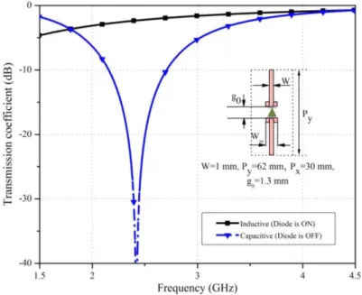
Fig. 3-1 Transmission response of an active FSS screen constructed of discontinuous capacitive loaded strips. ... 47
Fig. 3-2 (a) Proposed magneto dielectric FSS unit cell dimensions. (b) Specific boundary conditions and defined Floquet port excitation to extract scattering parameters. The unit cell dimensions are Lcell=46, Wcell=30, Ls1=26.5, Ls2=5, S=1.3, g=1, all in millimetre. ... 48
Fig. 3-3 Effective constitutive parameters of the magneto-dielectric FSS wall. ... 48
Fig. 3-4 Transmission response of the magneto-dielectric FSS wall. ... 49
Fig. 3-5 Active element mode used in the simulations and its effect on the EM response of the discontinuous strips unit cell. (a) Actual PIN-Diode electrical circuit model used in the simulation. (b) Simulated transmission coefficient of the discontinuous strips ... 49
Fig. 3-6 Geometry of the proposed omnidirectional monopole antenna... 50
Fig. 3-7 Simulated and measured reflection coefficients results of the proposed omnidirectional monopole antenna. ... 51
Fig. 3-8 Simulated and measured radiation pattern of the proposed omnidirectional monopole antenna at 2.45 GHz. ... 51
Fig. 3-9 The proposed pattern reconfigurable active FSS antenna structure. (a) 3D view of the proposed pattern reconfigurable active FSS antenna. (b) Top view. Side view. ... 53
Fig. 3-10 Geometry of the cylindrical reflector antennas and FSS reflector. ... 54
Fig. 3-11 Simulated and measured reflection coefficient results, carried out for the proposed octagonal corner-reflector active FSS antenna geometries shown in Figs. 3-9. The walls number 1, 2 and 3 are active. ... 55
Fig. 3-12 Simulated and measured Radiation pattern results, carried out for the proposed octagonal corner-reflector active FSS antenna geometries shown in Figs. 3-9. The walls number 1, 2 and 3 are active. ... 56
Fig. 3-13 Photo of the proposed fabricated octagonal corner-reflector active FSS antenna prototype. .... 58
Fig. 3-14 Measured results for octagonal corner-reflector active FSS antenna (a) Reflection coefficient. (b) H-plane radiation-pattern. (c) E-plane radiation-pattern. ... 60
Fig. 3-15 Output Voltage Vs Input Power for the RF power detector (with part number: ZX47-60LN+). ... 61
Fig. 3-16 Free-space propagation loss with two horn antenna versus the distance. ... 61
Fig. 3-17 The practical antenna measurement setup. ... 62
Fig. 3-18 Photo of the antenna measurement setup. ... 62
Fig. 4-1 Photo of the antenna control unit. ... 64
Fig. 4-2 The functional block-schematic of the antenna control unit. ... 65
Fig. 4-3 The functional block-schematic of the antenna control unit. ... 65
Fig. 4-4 Schematic of the antenna control unit. ... 66
[6]
Fig. 4-6 (a) Output Voltage Vs Input Power for the RF power detector (with part number: ZX47-60LN+). (b) Slope versus frequency over temperature range. ... 68 Fig. 6-1 Réponse de transmission d'un écran FSS actif constitué de bandes chargées capacitives
discontinues... 73 Fig. 6-2 (a) Dimensions de la cellule unitaire FSS diélectrique magnéto proposée. (b) Conditions limites particulières et définie l'excitation du port Floquet pour extraire les paramètres de diffusion. Les
dimensions des cellules unitaires sont Lcell = 46, Wcell = 30, Ls1 = 26,5, Ls2 = 5, S = 1,3, g = 1, toutes en millimètre. ... 74 Fig. 6-3 Paramètres constitutifs efficaces de la paroi FSS magnéto-diélectrique. ... 74 Fig. 6-4 Réponse de transmission du mur FSS magnéto-diélectrique. ... 75 Fig. 6-5 Mode élément actif utilisé dans les simulations et son effet sur la réponse EM de la cellule unitaire des bandes discontinues. (a) Modèle actuel de circuit électrique à diode PIN utilisé dans la
simulation. (b) Coefficient de transmission simulé des bandes discontinues ... 75 Fig. 6-6 Géométrie de l'antenne monopôle omnidirectionnelle proposée. ... 76 Fig. 6-7 Les coefficients de réflexion simulés et mesurés résultent de l'antenne monopôle
omnidirectionnelle proposée ... 77 Fig. 6-8 Modèle de rayonnement simulé et mesuré de l'antenne monopôle omnidirectionnelle proposée à 2.45 GHz. ... 77 Fig. 6-9 La structure d'antenne FSS active reconfigurable de modèle proposée. (a) Vue 3D de l'antenne FSS active reconfigurable de modèle proposée. (b) Vue de dessus. Vue de côté. ... 79 Fig. 6-10 Géométrie des antennes à réflecteur cylindrique et réflecteur FSS. ... 80 Fig. 6-11 Les résultats des coefficients de réflexion simulés et mesurés, réalisés pour les géométries d'antennes FSS actives de coin-réflecteur d'angle proposées, représentées sur les Figs. 6-9. Les murs 1, 2 et 3 sont actifs. ... 81 Fig. 6-12 Des résultats de diagramme de rayonnement simulés et mesurés, réalisés pour les géométries d'antennes FSS activées par le réflecteur de coin octogonal proposé, représentées sur les Figs. 6-9. Les murs 1, 2 et 3 sont actifs. ... 82 Fig. 6-13 Photo du prototype de l'antenne FSS activé à l'angle octogonale de l'invention. ... 84 Fig. 6-14 Résultats mesurés pour l'antenne FSS active du réflecteur angulaire octogonale (a) Coefficient de réflexion. (B) diagramme de rayonnement du plan H. (C) diagramme de rayonnement en plan E. ... 86 Fig. 6-15 Tension de sortie Vs Puissance d'entrée pour le détecteur de puissance RF (avec numéro de pièce: ZX47-60LN+). ... 87 Fig. 6-16 Perte de propagation de l'espace libre avec une antenne à deux canaux par rapport à la distance. ... 87 Fig. 6-17 La configuration pratique de la mesure de l'antenne. ... 88 Fig. 6-18 Photo de la configuration de la mesure de l'antenne. ... 88
[7]
List of Tables
Table 1: Survey of the octagonal corner-reflector active FSS antenna. ... 63 Table 2: Sondage de l'antenne FSS active de réflecteur angulaire octogonal. ... 89
[8]
ABSTRACT
With the widespread improvement of wireless communication systems and appearing the new generation of mobile telecommunications such as 4G as well as 5G, a transmission of information with high data rate is feasible. Antenna is an important part of telecommunication systems where the information is transmitted and received. Most importantly, to improve the communication link and cover more users, in particular in base station antenna, it is necessary to steer the beam radiation of the antenna. This can be carried out mechanically as well as electronically which each one has its drawback and advantage. In mechanical approach, the installation infrastructure brings more difficulty. Also, in electronic methods due to using the phase shifter, it incurs a large loss and complexity to the design. In this thesis, first and foremost, a reconfigurable radiation pattern antenna based on frequency selective surfaces is introduced. To implement that idea, a modified electric-field coupled (ELC) resonators is presented, which works at 2.4 GHz. To transmit and reflect the illuminated power a pin diode is integrated in the middle of ELC resonator, where by turning “on” or “off”, the resonant frequency of transmission coefficient is shifted to a desired frequency band.
Then, the stair-case monopole antenna operating at 2.4 GHz is proposed in the next part which is surrounded by octagon FSS walls, where each one consists of a 2x3 ELC inclusions. By switching “on” three FSS walls and keeping remaining walls in off-state, the radiation pattern in azimuth plane is switching from omnidirectional to directional pattern. To validate, a prototype of antenna along with eight FSS walls incorporated by pin-diode is fabricate and attached to the control unit part. The measured reflection coefficient of the antenna is less than -10 dB over 2.35-2.55 GHz. The measured radiation pattern in H-plane clearly shows a directional beam in different states with a measured realized gain of more than 5 dBi.
To receive a maximum power in a random angle, a transmitted antenna propagates power and the aforementioned antenna with FSS panel is switched in 8 cases by control unit part.
Finally, a design of control unit interface with proposed reconfigurable pattern antenna is presented and discussed in more details.
[9]
ACKNOWLEDGMENTS
First of all, I sincerely wish to thank my supervisor Prof. Tayeb A.Denidni, who gave me the opportunity to join his research group. It was a real pleasure for me to have such an exceptional scholar and it was my honor to be his master student.
Pattern Reconfigurable Antenna Based on Active Frequency Selective Surface chapter 1: Introduction
[10]
Chapter 1 Introduction
1.1 Motivation
Reconfigurability in terms of radiation pattern is crucial for wireless communications systems since it can improve the link quality and reduces the interference and most importantly increase the signal to noise ratio. Reconfigurable antennas offer flexibility in terms of frequency, pattern, and polarization, hence versatile and flexible operations in many applications. In fact, in a rich scattering environment, it is imperative to design antenna element with desired radiation patterns into a predefined angle so as to re-direct the beam radiation for covering more areas and users and suppressing the undesired signals from other directions. Thus, a multipath propagation fading can be reduced which in turn results in the improvement of spectral efficiency by taking into account the fact that the higher rate of information can be transmitted in a given bandwidth [1], [2].
Several works have been introduced to achieve a reconfiguarable radiation pattern such as the use of RF p-i-n diodes [3], [4], microelectromechanical system (MEMS) switches, varactor diodes, GaAs FET switches [5], or mechanical actuation. Reconfigurable antennas using p-i-n diodes suggest high reliability, fast switching speed, and more efficiency in terms of cost as opposed to MEMS [6]. Furthermore, more study has been investigated to substitute p-i-n diodes due to the power consumption of MEMS, high isolation, and considerable low insertion loss. However, they are costly and it is required a power-up converter chip to generate high voltages of 30–80 V [7].
The radiation pattern of the antenna element could be unidirectional, bidirectional, multidirectional or omnidirectional. In reconfigurable radiation pattern, the radiated beam can be redirected from one pattern to another one [7–12]. For instance, the radiation pattern of the antenna in [9] could be reconfigured from unidirectional to omnidirectional, wherein the radiation beam of the antenna in [8] could be reconfigured from bidirectional to unidirectional. For a unidirectional pattern, the main beam of the antenna can also be steered to different directions. A typical example of such type of beam steerable antennas is a phased-array antenna. As opposed to patch or slot antennas, a phased-array antenna has this capability to offer a more gain n and quick response to beam steering. Nevertheless, there are several drawbacks of phased-array antennas. First, the size of each phased-array element is usually about a half-wavelength long, making the generation of grating lobe as well as an increase in total size of the antenna arrays. Second, a phased-array antenna system is usually incorporated with complex active device network requiring a number of phase shifters and power amplifiers. This element incurs large losses as well as increases the cost of the whole phased-array antenna system. Third, the shape of radiation beam may alter over beam steering [13]. As a consequence, researchers have investigated lots of works on pattern reconfiguration applying low-profile and low-cost antennas [7–9, 14]. For instance, the square loop antenna proposed in [15] could steer the tilted main beam in four different quadrants and hence scan the entire space in front of the antenna. This was indeed a low-profile solution for beam steering and easy to implement. However, the beam could not be steered continuously since the antenna could only be switched among four different states.
Pattern Reconfigurable Antenna Based on Active Frequency Selective Surface chapter 1: Introduction
[11]
1.2 Problem identification
It is imperative to be familiar with link budget definition along with its performance to design appropriate system in this project. Thus, in this part, the explanation about the link budget is provided and we will present a conventional RF communication system to illuminate how we can maximize the link performance of the system by applying the proposed designed pattern reconfigurable antenna. In RF telemetry link the first parameter is the output power of the transmitter and the total gain as well as loss to recognize the real value of the power delivered to the receiver. To design a consistent link budget, the appropriate level of power in the receiver should be in excess of that required for a minimum level of performance.
An explanation of all the parameters such as gain as well as losses existed between the transmitter and the receiver is considered to as the link budget. The parameter of the link budget systems is included as shown in Fig. 1-1.
Fig. 1-1 System Gain-Loss Profile for a Link Budget[16].
Where:
Pattern Reconfigurable Antenna Based on Active Frequency Selective Surface chapter 1: Introduction
[12]
L_transmit = the loss of system in terms of dB at transmitter. GTX = the peak gain of antenna in terms of dBi at the transmitter.
Loss = the total losses of propagation losses in terms of dB between the antenna in transmitting
and receiving modes.
GRX = the peak gain of antenna in terms of dBi at the receiver. LRX = the entire system loss in terms of dB at the receiver. PRX = the delivered power at receiver in terms of dBm.
The power level which is in excess of than that needed for a defined minimum level of system characteristics is related to as the fade margin. Since, it provides a border of safety in the state of a transitory attenuation or fading of the received signal power. The smallest received power level deployed for the link budget can be fully random—based on the designer’s knowledge—but is most often related to the receiver’s sensitivity. In fact, the receiver’s sensitivity defines the least RF input power which is necessary to generate a functional output signal. A usual value for receiver sensitivity is in the range of –90 to –120 dBm.
To better recognize the mechanism of the link operation, we are employing a typical RF communication system called RF320 (INR RF320). This system includes:
RF320 radio (both ends): The output power corresponds to 5 watts (37 dBm); the sensitivity of the system should be 0.25 μV (–119 dBm) for 12 dB SINAD (signal-to-noise and-distortion ratio); the operating frequency corresponds to 2.45 GHz.
The radiation pattern of the antenna should be Omnidirectional and the peak gain corresponds to 3 dBd (5.15 dBi); VSWR (voltage standing wave ratio) < 2:1.
The connector loss corresponds to 0.5 dB.
The loss of transmission line at receiver and transmitter should be ≈ 0.5 dB.
The path loss of propagation is an unbarred line of sight (LOS) over a smooth earth. Assume, the total distance between the transmitter and receiver is equal to 32.2 k.
Base on abovementioned assumption we can estimate the link budget
The transmitted power:
The RF320 RF output power is defined in terms of watts. To generate the output power the following equation is deployed in terms of watts to power in dBm:
𝑃𝑑𝐵𝑚 = 10 log(𝑃𝑤𝑎𝑡𝑡𝑠) + 30 (1) The output power of the above mentioned system corresponds to 5 watts.
Thus:
𝑃𝑑𝐵𝑚 = 10 log(5 𝑤𝑎𝑡𝑡𝑠) + 30 (2)
𝑃𝑇 = 37 𝑑𝐵𝑚 (3)
The loss of the system is the summation of the whole insertion loss in the transmission line in addition of any loss because of the mismatch impedance matching with antenna. There are other components in the RF systems such as coaxial cables, as well as possibly even bandpass filters
Pattern Reconfigurable Antenna Based on Active Frequency Selective Surface chapter 1: Introduction
[13]
deployed to link the transceiver to the antenna, which causes a loss. In fact, each element in the transmission line which does not amplify will show some portion loss; a decrease in the level of output power compared to its input is known as insertion loss. In most states, the main loss will be considered to the insertion loss of the reasonably longer cable linking antenna mounted on tower. The characteristics of cable datasheet will naturally define its loss in a table indicating attenuation in dB per unit of length in terms of frequency.
When the output impedance of transceiver is matched to the antenna along with the transmission line, then the maximum power is delivered to antenna, however if there is a mismatch of impedance, it leads to a mismatch loss. It is possible that each component in the transmission line will demonstrate some small deviation from the standard 50 Ω characteristic impedance, and the net effect is the total of these cascading mismatches. However, the minimal effect of the transmission line on the link budget is neglected and the antenna mismatch is considered as the main loss. The most general impedance mismatch of the antenna called VSWR; for instance, VSWR < 2:1. The following equation is given to achieve a relation between the VSWR and mismatch loss.
𝑀𝑖𝑠𝑚𝑎𝑡𝑐ℎ 𝑙𝑜𝑠𝑠 = −10 log{1 − [𝑉𝑆𝑊𝑅 − 1 𝑉𝑆𝑊𝑅 + 1]
2} (4) Therefore, a VSWR of 2:1 equates to a mismatch loss of 0.511 db.
Based on the preceding information, we can now calculate the system loss for both ends of the link. 𝐿𝑜𝑠𝑠𝑇 = 𝑠𝑢𝑟𝑔𝑒 𝐾𝑖𝑡(−0.5) + 𝑐𝑎𝑏𝑙𝑒(−1.7) + 𝑐𝑜𝑛𝑛𝑒𝑐𝑡𝑜𝑟𝑠(−0.5) + 𝑚𝑖𝑠𝑚𝑎𝑡𝑐ℎ(−.0511) ≅ −3.2 𝑑𝐵 (5) 𝐿𝑜𝑠𝑠𝑅= 𝑠𝑢𝑟𝑔𝑒 𝐾𝑖𝑡(−0.5) + 𝑐𝑎𝑏𝑙𝑒(−0.85) + 𝑐𝑜𝑛𝑛𝑒𝑐𝑡𝑜𝑟𝑠(−0.5) + 𝑚𝑖𝑠𝑚𝑎𝑡𝑐ℎ(−.0511) ≅ −2.35 𝑑𝐵 (6)
Antenna Gain:
The value of the antenna gain employed in a link budget is presented in terms of dBi, which is in relation to state when the antenna radiates isotopically. It is conventional for a manufacturer’s datasheet to indicate the peak gain of antenna in units of dBd, which is the relative gain
compared to actual dipole antenna. In comparison with an isotropic radiator, a classical half wave vertical dipole antenna will demonstrate a gain of 2.15 dB in the azimuthal plane. The conversion of the gain in terms of in units of dBd to units of dBi is given as follows:
𝑑𝐵𝑖 = 𝑑𝐵𝑑 + 2.15 (7)
The RF320 antenna in the above example has a defined gain of 3 dBd. Thus, the estimation gain of transmitting and receiving antenna in terms of dBi is given as follows:
𝐺𝑎𝑖𝑛𝑇= 𝐺𝑎𝑖𝑛𝑅 = 3 + 2.15 (8)
Pattern Reconfigurable Antenna Based on Active Frequency Selective Surface chapter 1: Introduction
[14]
Path Loss:
In most states, the path loss is the key factor to loss in the link budget. It is the summation of free space loss along with the other losses induced by the interaction of the electromagnetic waves with the ground and/or obstacles along the direction of propagation.
The propagation of the Line-of-Sight:
In the most common RF link, the principle mode of electromagnetic waves propagates in line of sight, which is a direct path between the antenna in transmitting and receiving modes. Thus, for a single element antenna, the maximum direction of propagation is restricted by the distance to the RF horizon. As demonstrated in Fig. 1-2, the RF horizon is different from the optical horizon.
Fig. 1-2 Optical Horizon vs. RF Horizon.
The optical horizon originates from an optical straight path line which corresponds to a straight direction of distance from the antenna to a defined curve line to the earth’s surface. In fact, the RF signal travers a bend path line which is primarily located in parallel of the surface of the earth , however, it is curved because of the refractive index of the that is initially parallel to the earth’s surface but is progressively bent toward the surface due to the refractive properties of the air. Thus, the space to the RF horizon point is roughly 7 percentages more than the space to the optical horizon. For a conventional atmosphere (which the refractive index is 1.33) over a flat earth, the distance to the RF horizon is determined based on the height of the antenna as follows:
𝑡𝐻𝑂𝑅 = 4.14√𝑙 (10) 𝑡𝐻𝑂𝑅= relative space to the Rf horizon in terms of kilometers
l= the distance of the antenna to earth
In the RF system link, the maximum line-of-sight path space corresponds to the summation of the RF distance point when the antenna works in transmitting and receiving mode:
Pattern Reconfigurable Antenna Based on Active Frequency Selective Surface chapter 1: Introduction
[15]
Thus, for the aforementioned RF link:
𝐻𝐿𝑆𝑀𝐴𝑋 = 4.4√30 + 4.4√10 (12)
𝐻𝐿𝑆𝑀𝐴𝑋 = 35 𝑘𝑚 (13)
In order to the Rf link to be taken into account as line of sight, the space of the antenna in two modes of transmitting and receiving should be the same or less than the maximum line of sight path length as follows :
𝑡𝑃 ≤ 𝐿𝑂𝑆𝑀𝐴𝑋 (14)
Thus, when the distance between the transmitter and receiver antenna is 32 km we can consider proposed RF link as LOS since its value is less than maximum estimation which is 35 km.
Free Space Model:
When electromagnetic waves propagate in free space density of the power is minimized. These facts give rise to the classic free space loss equation:
𝑑𝑓𝐿𝑑𝐵 = 32.5 + 20 log(𝑡) + 20 log(𝑓) (15)
Where:
𝑑𝑓𝐿𝑑𝐵 = free space loss in terms of dB t = distance in terms of kilometers 𝑓= frequency in terms of Gigahertz
Thus, for a distance of 32.1 km and the frequency of 2.45 GHz:
𝑑𝑓𝐿𝑑𝐵 = 32.5 + 20 log(32.1) + 20 log(2.45) (16)
𝑑𝑓𝐿𝑑𝐵 = 107.2 𝑑𝐵 (17)
However, the loss of free path length is deployed in the estimation of link budget it is imperative to be aware of that in this section. In fact, the expressions free space means that there is no atmosphere as well as no curved surface. Thus, this does not represent a real environment to calculate the precise link budget.
2-Ray Multipath Propagation:
In the real environment the electromagnetic waves will face unavoidable things or a natural obstruction which restricts the calculation of link budget .In fact, the electromagnetic waves will
Pattern Reconfigurable Antenna Based on Active Frequency Selective Surface chapter 1: Introduction
[16]
be scattered, refracted as well as diffracted which we have to consider the effect of multipath ray propagation in estimation of link budget.
If we do not have a precise knowledge about the propagation of the EM wave in this situation, it would be hard to distinguish the received signal in the receiver. For that purpose we deploy a software application employing established experimental propagation models linked to a GIS database to estimate the losses for blocked line-of sight path of propagation.
In fact, a conventional atmosphere as well as a free path line over a flat earth will be considered. In the case when the receiver receives the signal, it is hard to say that the EM wave is related to direct path length. In most cases, the received signal is the combination of reflected wave as well as line of sight signal. Thus, the captured signal by the receiver is the summation of the amplitude and phase of line of sight direction and reflected signal.
In the free line of sight path, the most source of reflection is the curvature of the earth. This can cause a considerable effect when the distance between transmitter and receiver antenna is enough large. The configuration of direct path and reflected path for two rays of propagation is revealed in Fig. 1-3.
Fig. 1-3 Path Geometry for 2-Ray Propagation Model.
In fact, the reflected signal captured in the receiver has different amplitude and phase in comparison with the direct incident wave. The phase difference is attributed to the different path length of incident as well as reflected wave arriving at receiver. When the EM wave is polarized horizontally, there is a 180 degree in the point of reflection .Conversely, in the vertical polarization, the reflected wave has a phase shift when the angle of incidence is less than 30 degree, and also this can be equal 180 degree if the angle of incident wave is very small.
A large path direction has considerable effect on the amplitude of the reflected EM wave .The effect of combination of reflected EM wave along with the incident wave can be constructive or destructive. The positive effect happens when the EM wave is captured in phase (𝜃𝑑𝑖𝑓𝑓 < ±90). In fact, when there is a zero phase shift and small variation in amplitude in return gives raise a 6 dBi gain in received signal strength as opposed to LOS EM wave. Also, when the wavefront is captured in the receiver by phase (𝜃𝑑𝑖𝑓𝑓 > ±90), the reflected signal is out of phase with direct signal which has negative effect. Thus, this results in a cancellation of the signal and noting is delivered in the receiver
Pattern Reconfigurable Antenna Based on Active Frequency Selective Surface chapter 1: Introduction
[17]
The power level of received signal:
Assuming, the input parameters of the link budget is defined and known , then the level of the received power in the receiving mode can be estimated as follows .
From Fig. 1-1:
𝑃𝑅𝑋 = 𝑃𝑇𝑋− 𝐿𝑇𝑋+ 𝐺𝑇𝑋− 𝐿𝑃𝐴𝑇𝐻+ 𝐺𝑅𝑋 − 𝐿𝑅𝑋 (18)
Thus, the power received in the conventional RF320 system is as follows:
𝑃𝑅𝑋 = 37 𝑑𝐵𝑚 − 3.2 𝑑𝐵 + 5.15 𝑑𝐵𝑖 − 13.8 𝑑𝐵 + 5.15 𝑑𝐵𝑖 − 2.35 𝑑𝐵 = −89 𝑑𝐵𝑚 (19)
It should be mentioned that the sensitivity of the receiver determines the minimum input power which is required to produce appropriate output power. There is a key factor for determining the sensitivity of the receiver as follows:
The required minimum input power to limit the errors in the received signal to a maximum Bit Error Rate (BER). The conventional value corresponds to: –103 dBm for 1 x 10⁻⁴ BER— specifying bit error for each 1000 bit .
For a 50 Ω system (the standard for the telecommunications industry), the following equation can be deployed to convert volts to power in dBm:
𝑃𝑑𝐵𝑚 = 10 log [(𝑉. 10 −6)2 50 ] + 30 (20) Where: PdBm = power in dBm V = rms voltage in microvolts
Thus, the sensivity of the usual RF320 system is given by: Rx Sensitivity at 0.25 uV for 12 dB SINAD
𝑅𝑥 𝑆𝑒𝑛𝑠𝑖𝑡𝑖𝑣𝑖𝑡𝑦 (𝑃𝑑𝐵𝑚) = 10 log [(0.25. 10 −6)2
50 ] + 30 (21)
𝑅𝑥 𝑆𝑒𝑛𝑠𝑖𝑡𝑖𝑣𝑖𝑡𝑦 = −119 𝑑𝐵𝑚 (22)
Fade Margin:
Pattern Reconfigurable Antenna Based on Active Frequency Selective Surface chapter 1: Introduction
[18]
If we subtract the sensitivity of the receiver from the estimated received power, we can obtain the value to which transmitted path losses or signal fading can be tolerated before system performance is affected.
1. 3 Problem remedies and project objectives
In previous section, we discussed about the link budget and the system parameters of a typical communication link (INR RF320). As explained the performance of communication system is presented by the defined bit error rate (BER) curve. For achieving such a BER curve for a wireless communication link, it is imperative to explain the sub-system parameters such as maximum coverage area, as well as fad margin
A wireless local area network (WLAN) is a wireless computer network that connects two or more users deploying a wireless distribution method (often spread-spectrum or OFDM radio) in a limited area such as a home, school, computer laboratory, or office building. This brings about users the ability to move around within a local coverage area and yet still be linked to the network.
A WLAN can also prepare a broadband connection to the Internet. Most modern WLANs are based on IEEE 802.11 standards and are marketed under the Wi-Fi brand name. Fig. 1-4 shows the allocated channels for IEEE 802.11 standards.
Pattern Reconfigurable Antenna Based on Active Frequency Selective Surface chapter 1: Introduction
[19]
Fig. 1-4 Allocated channel for IEEE 802.11 standards.
(a)
Pattern Reconfigurable Antenna Based on Active Frequency Selective Surface chapter 1: Introduction
[20]
In Fig. 1-5, we calculated the received power with considering an omnidirectional antenna as the radiating element in access point, and for mobile targets. As it is illustrated in Fig. 1-5, the maximum coverage area is considered to be 50 m. If we imagine that the receiver sensitivity is -80dBm, which means in the worst case we need -80dBm received power at the receiver to have the desired BER in the receiver baseband section. As it is shown in Fig. 1-5, the received power in the receiver for the maximum distance condition in the best scenario (unobstructed line-of-sight (LOS) without any channel fading) is 8dBm lower than sensitivity of the receiver Detecting such a signal will cause a huge amount for BER in the baseband section.
Fig. 1-5 A typical wireless local area network with considering an omnidirectional antenna as the radiating element in access point, and mobile targets.
Receiver Gain=15db Input P1dB=-6dBm Omni-Directional Antenna Gt=Gain=2.5dB Transmitter Pt Receiver Chain R 𝑃𝑜𝑤𝑒𝑟 =4𝑃𝑡𝐺𝑡 3 𝜋𝑅3 𝑃𝑜𝑤𝑒𝑟 =𝑃𝑡4𝐺𝑡𝐺𝑟𝐴𝑟 3 𝜋𝑅3 0dBm
For minimum distance (R=10m) ……. -60dBm For Maximum distance (R=50m) ……. -85dBm
For minimum distance (R=10m) ……. -63dBm For Maximum distance (R=50m) ……. -88dBm Signal
Processing
For minimum distance (R=10m) ……. -48dBm For Maximum distance (R=50m) ……. -73dBm
Pattern Reconfigurable Antenna Based on Active Frequency Selective Surface chapter 1: Introduction
[21]
If we considered the topology in Fig. 1-6 with a pattern reconfigurable antenna for the access point side, we can improve the link performance in different aspects.
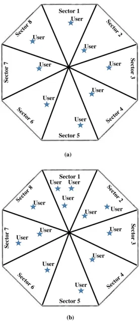
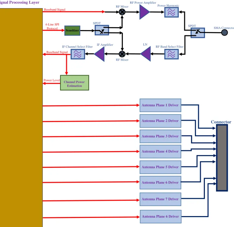
The first thing is that it compensate for the maximum distance condition signal level which is lower than 8dbm below the sensitivity of the receiver. As it is illustrated in Fig. 1-6, the received signal power is higher than sensitivity in the same situation as Fig. 1-5. In this system we should have knowledge about the position of the mobile device to be able to focusing the radiation pattern toward the target; this can be done by searching the space by the pattern reconfigurable antenna and reading the received power level at different directions. However, in a more complicated system with more than one user, we need to have a network signal processing protocol for having the best performance for all the users. If the users are in different sectors of the pattern reconfigurable antenna (Fig. 1-7a), we are able to detect them one by one and define their distance and their angle. However, if we have two or more users in one sector (Fig. 1-7b), it is impossible to define their number and their distance. In this situation, we need to read the power after demodulating the different channels; in order to do this, we need to read the power after channel detection. Fig.1-8 shows the proper place for estimating the channel power, and the proper topology for the receiver of a system with a pattern reconfigurable antenna. In this receiver topology, we consider an 8-sector pattern-reconfigurable antenna system.
In this thesis, the structure shown in Fig. 1-7(b) is not deployed since the purpose of this thesis is designing the reconfigurable antenna based on FSS inclusions. In fact, there is no receiver, a digital control unit is designed to verify the performance of the pattern reconfigurable antenna. This can be implemented by RF power estimation for user detection. To implement the aforementioned scenario in Fig. 1-7b, it is crucial to possess a complete receiver to estimate the power of different users.
Pattern Reconfigurable Antenna Based on Active Frequency Selective Surface chapter 1: Introduction
[22]
Fig. 1-6 A typical wireless local area network with considering a pattern reconfigurable antenna as the radiating element in access point, and an omnidirectional antenna for mobile targets.
Receiver Gain=15db Input P1dB=-6dBm Omni-Directional Antenna Gt=Gain=2.5dB Transmitter Pt Receiver Chain R 𝑃𝑜𝑤𝑒𝑟 =4𝑃𝑡𝐺𝑡 3 𝜋𝑅3 𝑃𝑜𝑤𝑒𝑟 =𝑃𝑡4𝐺𝑡𝐺𝑟𝐴𝑟 3 𝜋𝑅3 0dBm
For minimum distance (R=10m) ……. -60dBm For Maximum distance (R=50m) ……. -85dBm
For minimum distance (R=10m) ……. -53dBm For Maximum distance (R=50m) ……. -78dBm Signal
Processing
For minimum distance (R=10m) ……. -48dBm For Maximum distance (R=50m) ……. -73dBm
Pattern Reconfigurable Antenna Based on Active Frequency Selective Surface chapter 1: Introduction
[23]
Fig. 1-7 Different users’ locations scenario. a) Location detectable using RF power estimate. b) Location detectable using channel power estimate.
Sector 1 S ec to r 3 Sector 5 S ec to r 7 User User User User User User User User Sector 1 S ec to r 3 Sector 5 S ec to r 7 User User User User User User User User User User User User (a) (b)
Pattern Reconfigurable Antenna Based on Active Frequency Selective Surface chapter 1: Introduction
[24]
Fig. 1-8 The proper topology for the receiver of a system with a pattern reconfigurable antenna.
RF Band Select Filter
SMA Connector SPDT
Switch
LN A IF Channel Select Filter
RF Power Amplifier Power Harmonic Filter Sensitizer SPDT Switch
Signal Processing Layer
4-Line SPI Protocol Baseband Signal Baseband Signal IF Amplifier Channel Power Estimation Driver Power Level
Antenna Plane 1 Driver
Antenna Plane 2 Driver
Antenna Plane 3 Driver
Antenna Plane 4 Driver
Antenna Plane 5 Driver
Antenna Plane 6 Driver
Connector
RF Mixer
RF Mixer
Antenna Plane 7 Driver
Pattern Reconfigurable Antenna Based on Active Frequency Selective Surface chapter 1: Introduction
[25]
1. 4 Thesis executive summary and accomplishments
To accomplish the aforementioned approaches, a literature review about reconfigurable antennas is investigated in Chapter 2. In fact, the radiation beam of the reconfigurable antenna is discussed and its effect on the link budget will be presented. In Chapter 3, more details about the reconfigurable antennas based on active FSS cells is presented. In Chapter 4, the control unit is designed and discussed to develop an electronically reconfigurable radiation beam antenna.
Pattern Reconfigurable Antenna Based on Active Frequency Selective Surface chapter 2: Literature Review
[26]
Chapter 2 Literature Review on Pattern-
Reconfigurable Antennas
2.1 Introduction
Wireless communication systems are extending toward multi-task environments for different applications. This multi objective prepares the users to be linked to various services and connections with variety of services at different time slots. It is evident that a lot of antennas are integrated into aircrafts or other vehicles; it is therefore appropriate to provide a single antenna element which has different functionalities to be placed in small area for different applications. A radiating element which has this capability to change its properties, such as the resonant frequency, polarization or radiation beam, can be considered as a reconfigurable antenna. A reconfigurable antenna has this ability to provide additional characteristics and degree of freedom to wireless communications and users to improve the link quality and enhance the performance of the systems. The main objective of reconfigurable antenna is to reduce the number of elements for specific applications; however, it can be applied for sophisticated applications such as phased array systems as well as MIMO systems. Additionally, the reconfigurability in terms of radiation pattern is the alternative approach as opposed to phased array and adaptive array systems. A reconfigurable Antenna gives us this permission to allocate the desired spectrum in multi-band wireless communication systems. Also, it brings about a minimum number of antenna element, most importantly, it reduces the dimension of the antenna. There are different techniques to implement a reconfigurablity in terms of radiation pattern, such as using tunable elements in the feeding networks, employing phase shifters and tunable filters, tunable elements embedded such as PIN diodes, MEMS (switches, varactors, and moveable parts) and optical switching in the radiating elements, mechanically moveable radiating elements.
2. 2 Reconfigurable Antenna Base on Active Bowtie FSS
The configuration of the antenna element presented in [17] is a hexagonal cylinder and is comprised of two major parts [17]. The antenna element is dipole and is located in the middle of the structure. In fact, the antenna element acts as an excitation source and the remaining parts are frequency selective surface inclusions. To create FSS unit cell, a bow-tie shape is deployed and its constituted parameters was calculated. When the diode is switched on, the FSS unit cell acts in the transmission mode, and when the diode is switched off, the FSS lattices work in reflection
Pattern Reconfigurable Antenna Based on Active Frequency Selective Surface chapter 2: Literature Review
[27]
state, which has different characteristic compared to conventional ones. The proposed structure consists of 3 sidewalls operating in transmission mode and 3 sidewalls working in reflection mode, where it acts as a reflector. The measurement results reveal that the radiation beam can be steered in six steps along the entire azimuth plane with average gain of 5dBi where the beamwidth corresponds to 80° at 2.5GHz. Thus, these simple and low cost structures propose an excellent candidate for wireless communication systems and low power base station systems. In fact, the proposed inclusion is comprised of a bow-tie lattice with a length of L=110 mm and a width of W=46 mm. A PIN diode is integrated in the middle of bow-tie cell shown in Fig.2-1 to change the state from transmission to reflection. The magnitude of the S11 for the proposed unit cell when it is working in the transmission and reflection mode was achieved and shown in Fig.2-2.
There is a bi-cone dipole located at the center of the hexagonal cylinder as an excitation source as shown in Fig. 2-3. The operation of this reconfigurable antenna can be described as follows. In fact, when the pin diode is switched on, the FSS unit cell works in the transmission mode for the incident electromagnetic wave; when the diode is switched off, the FSS inclusion acts as a reflector which reflects all of the incident waves. Thus, the FSS cells with off states of the hexagonal cylinder can reflect the incident electromagnetic wave to form a directional radiation pattern. By sequentially switching the states of the PIN diodes, this beam-switching antenna is able to steer the radiation pattern along the azimuth plane. The measured reflection coefficient in terms of different bias configurations is shown in Fig. 2-4. The measured radiation pattern of the antenna, when 3 sidewalls are switched on at 2.5 GHz, is shown in Fig.2.5.
Pattern Reconfigurable Antenna Based on Active Frequency Selective Surface chapter 2: Literature Review
[28]
Fig. 2-2 Reflection coefficients of both diode turn-on and turn-off state [17].
Fig. 2-3 Reflection coefficients of both diode turn-on and turn-off state [17].
Pattern Reconfigurable Antenna Based on Active Frequency Selective Surface chapter 2: Literature Review
[29]
Fig. 2-5 Simulation result of X-Y plane 2D radiation pattern [17].
2. 3 Reconfigurable Antenna Based on Reconfigurable FSS
The active FSS is comprised of the number of unit cells that permit to switch the radiation pattern of the antenna into a desired direction. The approach consists of an active cylindrical FSS structure which contains a number of PIN diodes and is comprised of 10 equal columns. Then, in the middle of the array of FSS walls, a classical dipole antenna is embedded. The radiated beam of the antenna is steered by turning on and off of the PIN diodes. The measured antenna gain working at 1.8 GHz corresponds to 9.1 dBi which covers all azimuth angles in 10 steps. This structure is an excellent candidate for base station applications [18].This FSS inclusion shown in Fig.2.6 consists of two elements: an array of circle loops along with a discontinuous strip. To achieve reconfigurability in terms of transmission coefficient of the FSS unit cell, a PIN diode is integrated in the middle of the rectangular strip. The result of the proposed FSS lattice in terms of transmission and reflection coefficient is revealed in Fig. 2-6.
The configuration of proposed FSS flexible surface which forms of the cylinder is located in the surrounding of dipole as shown in Fig.2-7. The active FSS structure is comprised of 10 columns, where each panel includes three FSS scatters. In the top of each FSS panel, an RF-choke as well as a resistor is attached to the whole FSS unit cell, and the RF-RF-choke is attached in the below of FSS cells. The main objective of RF-chokes is to prevent the effect of direct current feeding on the FSS unit cells. Also, the main role of resistor is to restrict the biasing current of diodes.
Pattern Reconfigurable Antenna Based on Active Frequency Selective Surface chapter 2: Literature Review
[30]
To change the radiation pattern of the dipole antenna from omnidirectional to directional, it is crucial to switch the FSS columns between ON and OFF states. For each angle, the diodes for the specific sector are turned ON whereas the other diodes are switched OFF. In the On state, the EM waves of the dipole propagates into a desired direction while in the off state the FSS unit cells prevent the propagation and reflect all of the radiated signals. The specific sector, which is defined by the size of the aperture of the reflector, can be estimated by the number of columns when the FSS cells are turned ON. As shown in Fig. 2-8, the maximum value of the directivity is achieved when all three columns work in the ON state. The comparison between the simulation and measurement results of the proposed FSS antenna is shown in Fig.2.9.Also, the radiation pattern in both E and H-planes at 1.8 GHz are shown in Fig.2.10.
Fig. 2-6 Transmission and reflection responses of the proposed active FSS unit cell [18].
Pattern Reconfigurable Antenna Based on Active Frequency Selective Surface chapter 2: Literature Review
[31]
Fig. 2-8 Effect of number of columns (in ON state) on gain of the proposed antenna [18].
Fig. 2-9 Reflection coefficient of the cylindrical active FSS [18].
Fig. 2-10 Measurement and simulation radiation pattern of the proposed antenna in the directional mode: (a) H-plane; (b) E-plane [18].
Pattern Reconfigurable Antenna Based on Active Frequency Selective Surface chapter 2: Literature Review
[32]
2. 4 Beam Steering with Integrated Ferroelectric Varactors
The main objective of FSS is to act as a transmitarray with a bandpass property in Ku-band [19]. The FSS scatters consist of a capacitive and inductive element which generate a bandpass for the illuminated waves. By changing the capacitive value of the FSS cells on a screen-printed barium strontium-titanate (BST) thick-film ceramic, its operating frequency is altered. Thus, this technique proposes a low-cost and simple approach suitable for incorporating varactor diodes into the FSS cell. A fabricated structure of FSS unit cell consists of two capacitive layers which the total size corresponds to 40 mm x 40 mm. Also, each panel composed of a maximum number of 1600 integrated BST varactors that are fabricated by deploying a chemical as well as metallization process. An illuminated waves passing through the FSS wall will cause a phase shift, which can be tuned by tuning the passband. This cause the transmitted waves deflect to a predefined angle by employing a gradient phase over the FSS unit cell. In fact, a 360 degree phase shift is achieved by creating a multilayer FSS panel. The fabricated FSS panel proves its application for steering the illuminated wave into a pre-defined direction.Fig. 2-11 reveals the methodology of a transmitarray for steering the radiated beam, where includes two antennas in the receiver and transmitter, respectively as well as a beam forming network between them. The aforementioned FSS scatter is comprised of three layers. In fact, a thin layer is deployed to realize the tuning of capacitors. In the light of the periodicity of the FSS cells which are repeated in each direction, a single cell with defined boundary conditions is taken into account.
Fig. 2-13. demonstrates the schematic of the capacitive layer of FSS cells with 20 bias channels provided for fabrication. On the right side, each second row is attached to an individual bias pad, and on the left, all other rows are dc grounded. Fig. 2-14 shows the measured radiation patterns of the FSS in three tuning states.
Fig. 2-11 a) The concept of a transmitarray for beam steering, which consists of two antenna arrays for receiving and transmitting, respectively, and a beam forming network between them. b) A tunable FSS with phase shifting
Pattern Reconfigurable Antenna Based on Active Frequency Selective Surface chapter 2: Literature Review
[33]
Fig. 2-12 a) Proposed FSS consists of 3 metallization layer on two substrates. Thin BST layer are implemented for tuning the capacitors. Due to the periodicity, a single unit-cell with periodic boundaries is considered in
simulations[19].
Fig. 2-13 The layout of the capacitive layer of FSS with 20 bias channels prepared for prototyping. On the right side, every second row is connected to an individual bias pad, and on the left, all other rows are dc grounded [19].
Pattern Reconfigurable Antenna Based on Active Frequency Selective Surface chapter 2: Literature Review
[34]
Fig. 2-14 Measured radiation patterns of the FSS in three tuning states. All curves are normalized to the maximum power in the untuned case. The radiation angle is steered between . The results are fitted with an analytical model.
Pattern Reconfigurable Antenna Based on Active Frequency Selective Surface chapter 2: Literature Review
[35]
2. 5 High-Gain Reconfigurable Sectoral Antenna
The FSS unit cell composed of metallic scatters with PIN diodes in each cell, and it is embedded cylindrically in the surrounding of the dipole antenna which has an omnidirectional radiation pattern [20]. The FSS configuration is composed of two semi-cylinders. By changing the state of each column and switching the PIN diode on or off, a radiated beam of the antenna can be steered into a predefined angle. The impact of the each pin diode as well as the radius of the cylindrical structure is carefully investigated to achieve the best directive radiation pattern in desired direction. In addition, an approach to enhance the reflection coefficient of the dipole antenna is also presented. A prototype of the dipole antenna along with FSS cells is fabricated and the measurement results indicate that the beamwidth in the azimuth and elevation planes at 2.1 GHz corresponds to 20 and 70 degree with a maximum realized gain of 13 dBi. Thus, this structure is an excellent case for outdoor wireless communication system. The above mentioned inclusion proposed in Fig. 2-15(a), is comprised of a metallic lattice where a pin diode is integrated into each strip .Fig. 2-16 reveals the transmission and reflection coefficient of the proposed FSS inclusion when the pin diode is turned on and off. To achieve a high-gain characteristic with reconfigurable radiation pattern, an array of dipole antenna was designed and placed in the middle of FSS panels illustrated in Fig. 2-17(b). In Fig. 2-18 the result of the reconfigurable radiation pattern is shown .
Fig. 2-15 (a) Schematic of the FSS unit cell (all the dimensions are in millimeters), (b) on-state equivalent circuit, (c) off-state equivalent circuit[20].
Pattern Reconfigurable Antenna Based on Active Frequency Selective Surface chapter 2: Literature Review
[36]
Fig. 2-16 Magnitude of the transmission and reflection coefficients of the FSS unit cell in on- and off-states[20].
Pattern Reconfigurable Antenna Based on Active Frequency Selective Surface chapter 2: Literature Review
[37]
Pattern Reconfigurable Antenna Based on Active Frequency Selective Surface chapter 2: Literature Review
[38]
2. 6 Agile Radiation-Pattern Antenna
The design of smart antenna working at 2.45 GHz is presented by deploring FSS scatters integrated by pin diode. In fact, by operating the FSS unit cell in two modes of transmission and reflection the illuminated waves by dipole can be manipulated for achieving a reconfigurable radiation pattern in the azimuthal plane. The cylindrical FSS unit cell located around the antenna can sweep the radiation beam in azimuth plane. The measurement results indicate that the sweeping the beam can be implemented. The impedance matching of the antenna corresponds to 200 MHz. Also, the back lobe radiation of the antenna is equal to 13 dB at 2.55 GHz. The measured and simulated reflection coefficient of the proposed FSS antenna is shown in Fig.2.19. It proves that the matching of the antenna is around 200 MHz. Fig. 2-20 demonstrates the 3D configuration of the Antenna structure with FSS. This antenna is comprised of an active cylindrical frequency selective surface (ACFSS) illuminated by a classical dipole located at its center. To prove the aforementioned concept, the antenna radiation pattern was measured at different frequencies over the operating bandwidth of dipole antenna. It can be observed in Fig.2-21 that the best operation of the antenna occurs at the frequency of 2.55 GHz, whereas the magnitude of reflection coefficient corresponds to 10 dB. There is a good agreement between simulation and measured ones. The radiation pattern is directive and the back-lobe level is more than 13 dB. The discrepancy between the simulation and measured results is attributed to the RF-cable effect, feed-line loading on the EM response of the FSS screen, as well as fabrication tolerances.
Pattern Reconfigurable Antenna Based on Active Frequency Selective Surface chapter 2: Literature Review
[39]
Fig. 2-20 Proposed antenna configuration (all dimensions are in mm). (a) Distributed configuration of the proposed FSS screen. (b) Cross section of the proposed ACFSS [21].
Pattern Reconfigurable Antenna Based on Active Frequency Selective Surface chapter 2: Literature Review
[40]
Fig. 2-21 Measured (2.55 GHz) and simulated (2.45 GHz) H-plane radiation patterns [21].
2. 7 Dual-Band Beam-Sweeping Antenna Based on Active
Frequency Selective Surfaces
This antenna is composed of a dual-band omnidirectional monopole antenna operating at 2.45 GHz and 5.2 GHz and two cylindrical AFSS screens [22]. The dual-band omnidirectional monopole antenna is designed as a radiating source and surrounded by the proposed two cylindrical AFSS screens. The unit-cells of the two proposed AFSS screens consist of two metallic crosses connected by a pin-diode vertically. By switching the pin-diodes, the transmission and reflection characteristics of unit-cell of the two AFSS are investigated, respectively, at their own operating frequency. This leads to the variation of the radiation pattern when the cylindrical AFSS screens are loaded around the monopole antenna. Therefore, by switching the pin-diodes with specified combinations, the dual-band beamforming antenna with multiple discrete states can be achieved at 2.45 GHz and 5.2 GHz.
The geometry of the proposed AFSS unit-cells operated at 2.45 GHz and 5.2 GHz are shown in Fig. 2-22. Each AFSS unit-cell contains two metallic crosses connected by a pin-diode in serial. Fig. 2-23(a) shows the simulated transmission coefficients of the 2.45 GHz AFSS unit-cell in both ON and OFF states, and Fig. 2-23(b), showing that electromagnetic waves are reflected and transmitted by the AFSS unit-cell at 5.2 GHz when the diode is ON and OFF.
The proposed band beam-sweeping antenna schematic is shown in Fig. 2-24. A dual-band monopole antenna in the center is designed as a radiating source and surrounded by two proposed cylindrical AFSS screens that have a common center. The operation mechanism of the
Pattern Reconfigurable Antenna Based on Active Frequency Selective Surface chapter 2: Literature Review
[41]
dual-band beam-sweeping antenna is stated as follows. For the outer cylindrical AFSS screen, it is divided into six parts. In each step of operation, three adjacent pin-diodes in three AFSS unit-cells are ON and the others are OFF. The AFSS unit-unit-cells with OFF-state diodes have a high transmission coefficient and almost transparent for incident electromagnetic waves radiated from the monopole antenna at the center and the other parts with ON-state pin-diodes provide a high reflection coefficient acting as a metallic reflector. This means three parts are open and the other three parts are closed to the propagation of electromagnetic waves. Therefore, the omnidirectional radiation pattern of the monopole antenna is converted into a directional one. The inner cylindrical AFSS screen works in the same operating method. The outer and inner cylindrical AFSS screens can work independently when they are placed in one antenna system. Therefore, by switching pin-diodes in different AFSS screens between the ON and OFF states, the radiation pattern could scan the entire azimuth plane by six steps at 2.45 GHz and 5.2 GHz at the same time. Different scenarios are defined in Fig.2-25 for testing the proposed antenna. Fig. 2-26 shows the measured radiation pattern results in the azimuth plane of Case I.
Pattern Reconfigurable Antenna Based on Active Frequency Selective Surface chapter 2: Literature Review
[42]
Fig. 2-23 Simulated transmission coefficients of the AFSS unit-cells: (a) 2.45 GHz AFSS unit-cell, (b) 5.2 GHz AFSS unit-cell [22]
Pattern Reconfigurable Antenna Based on Active Frequency Selective Surface chapter 2: Literature Review
[43]
Fig. 2-25 Operation methods: (a) Case I, (b) Case II, (c) and (d) Case III [21]
Fig. 2-26 Measured radiation patterns results in the azimuth plane of case I: (a) and (b) 2.45 GHz, (c) 5.2 GHz [22]
Pattern Reconfigurable Antenna Based on Active Frequency Selective Surface chapter 2: Literature Review
[44]
2. 8 Conclusion
The research survey on the topic of reconfigurable antenna demonstrates that still this topic is in the developing period and more multi-disciplinary research considering both hardware and software levels of the antenna system are demanded. Integrating reconfiguration mechanism into the antenna structure is one of the challenging topics in this area to alleviate or eliminate the undesired effect of the applied reconfiguration mechanism. Serving new technologies to propose more versatile reconfigurable structures is another attractive research area in this topic. Furthermore, introducing a smart element as components of an adaptive array antenna can also be an ultimate challenging configuration for the future modern smart communication systems.
Pattern Reconfigurable Antenna Based on Active Frequency Selective Surface chapter 3: Design of Pattern Reconfigurable Antenna
[45]
Chapter 3 Design of Pattern Reconfigurable
Antenna Based on Active Frequency
Selective Surface
3. 1 Introduction
In this chapter, the basic principles of transmission line theory of inductive and capacitive walls will be investigated and studied in details. These passive-periodic-arrays have been employed to achieve the proposed reconfigurable FSSs wall for controlling the incident electromagnetic waves for designing the proposed pattern-reconfigurable antenna at 2.45 GHz. This is achieved by reconfiguring the equivalent impedance of the screen seen by the incident plane waves from an inductive operation to a capacitiveoperation. An 8 panel antenna is selected to be designed with the proposed technique at 2.5 GHz. In the section 3.2, we will present and design the proposed active frequency selective with all the details. In Section 3.3, an omnidirectional antenna will be designed and discussed as a base antenna for embedding in the proposed pattern reconfigurable antenna. In Section 3.4, the complete pattern reconfigured antenna will be designed and simulated with all details. Finally in Section 3.5, the measured results will be presented and compared with the simulation ones.
3. 2 Proposed Active Frequency Selective Surface Wall
Fig. 3-1 shows a wire-strip as an active FSS wall. The S-parameters are shown in Fig. 3-1. A unit cell of this FSS consists of discontinuous capacitive-loaded dipole integrated with a surface mount PIN diode. By changing the PIN diode state, a reconfigurable stop-band response is achieved around 2.45 GHz. However, as it is shown in Fig. 3-1, when the diode in the unit cell is in active state, the FSS is not completely transparent for the incident vertically-polarized waves. This considerably deteriorates the desired directive radiation pattern of the proposed pattern-reconfigurable antenna. Therefore, the transmission characteristic of the FSS should be improved when it is going to be used in the transient state (i.e., for example in the case which all diodes are in active mode). We have studied the reason for this phenomenon. The first and straight forward solution is reducing the strip width up to a value limited by practical limitations which will somehow reduce this problem. However, the transmission characteristic still needs to be more enhanced. By studying the subject more deeply, we founded that this imperfect transition mode behavior is due to that the incident wave will see the FSS wall as a medium with different
![Fig. 2-1 Unit cell and the equivalent circuit model of PIN diode [17].](https://thumb-eu.123doks.com/thumbv2/123doknet/5006268.125025/27.918.238.627.647.1001/fig-unit-cell-equivalent-circuit-model-pin-diode.webp)
![Fig. 2-4 Measurement results of the reflection coefficient against the number of turn-on sidewalls [17]](https://thumb-eu.123doks.com/thumbv2/123doknet/5006268.125025/28.918.213.704.662.984/fig-measurement-results-reflection-coefficient-number-turn-sidewalls.webp)
![Fig. 2-6 Transmission and reflection responses of the proposed active FSS unit cell [18]](https://thumb-eu.123doks.com/thumbv2/123doknet/5006268.125025/30.918.226.694.345.685/fig-transmission-reflection-responses-proposed-active-fss-unit.webp)
![Fig. 2-10 Measurement and simulation radiation pattern of the proposed antenna in the directional mode: (a) H- H-plane; (b) E-plane [18]](https://thumb-eu.123doks.com/thumbv2/123doknet/5006268.125025/31.918.210.706.734.1019/measurement-simulation-radiation-pattern-proposed-antenna-directional-plane.webp)
![Fig. 2-16 Magnitude of the transmission and reflection coefficients of the FSS unit cell in on- and off-states[20]](https://thumb-eu.123doks.com/thumbv2/123doknet/5006268.125025/36.918.260.654.110.433/fig-magnitude-transmission-reflection-coefficients-fss-unit-states.webp)
![Fig. 2-26 Measured radiation patterns results in the azimuth plane of case I: (a) and (b) 2.45 GHz, (c) 5.2 GHz [22]](https://thumb-eu.123doks.com/thumbv2/123doknet/5006268.125025/43.918.129.794.679.892/fig-measured-radiation-patterns-results-azimuth-plane-case.webp)