HAL Id: hal-02484906
https://hal.archives-ouvertes.fr/hal-02484906v2
Submitted on 25 Feb 2020
HAL is a multi-disciplinary open access
archive for the deposit and dissemination of
sci-entific research documents, whether they are
pub-lished or not. The documents may come from
teaching and research institutions in France or
abroad, or from public or private research centers.
L’archive ouverte pluridisciplinaire HAL, est
destinée au dépôt et à la diffusion de documents
scientifiques de niveau recherche, publiés ou non,
émanant des établissements d’enseignement et de
recherche français ou étrangers, des laboratoires
publics ou privés.
Attacks toward Wireless Network-on-Chip and
Countermeasures
Arnab Kumar Biswas, Navonil Chatterjee, Hemanta Mondal, Guy Gogniat,
Jean-Philippe Diguet
To cite this version:
Arnab Kumar Biswas, Navonil Chatterjee, Hemanta Mondal, Guy Gogniat, Jean-Philippe
Diguet.
Attacks toward Wireless Network-on-Chip and Countermeasures.
IEEE Transactions
on Emerging Topics in Computing, Institute of Electrical and Electronics Engineers, In press,
�10.1109/TETC.2020.2973427�. �hal-02484906v2�
Attacks toward Wireless Network-on-Chip and Countermeasures
Arnab Kumar Biswas, Navonil Chatterjee, Hemanta Kumar Mondal,
Guy Gogniat and Jean-Philippe Diguet
Lab-STICC, CNRS / Université de Bretagne Sud, Lorient, France 56100
Final submission to IEEE TETC Feb. 6, 2020.
Introduction
A Wireless Network-on-Chip (WiNoC) offers a promising solution to reduce broadcast and long distance communication bottlenecks of conventional architectures by augmenting them with single hop wireless links. In this paper, we discuss new security vulnerabilities and countermeasures to protect against them in a WiNoC based system. In particular, we describe Malicious Threshold Configuration (MTC) Attack, Disruptive Token Passing (DTP) Attack, Data Stealing by Broadcast (DSB) Attack and Hybrid Attack against the WiNoC. Our proposed countermeasure against MTC-OU (over-utilization) attack i.e., Source Destination checking mechanism decreases wireless hub utilization by 49% and network latency by many orders of magnitude compared to without countermeasure, causing system performance
improvement. Another proposed countermeasure
against DTP attacks i.e., detour mechanism im-proves the network throughout by 1.21x and 23x under DTP-AHT and DTP-DOS attacks respectively.
Keywords:Wireless Network-on-Chip, Attack,
Countermeasure.
1
Introduction
Network-on-Chip (NoC) is a well known on-chip com-munication medium that is used to communicate packets between different processing elements inside a chip. Recent advances in Multiprocessor System-on-Chip (MPSoC) design and their corresponding in-crease in practical use cases call for strong security guarantees. NoC is an important component of any massively parallel MPSoC system and hence a secure NoC contributes to the overall system security.
Parallel applications running in high performance computing servers get performance benefits due to the use of NoCs in the server MPSoC chips. The pri-mary components of parallel applications are cache coherency and synchronization. Both of them face significant challenges during broadcast or multi-cast operations due to critical path communications. Con-ventional NoC architectures support broadcast op-erations in the form of multiple uni-cast transmis-sions, which results in significant system performance penalties concerning network latency and energy con-sumption overheads. A Wireless Network-on-Chip (WiNoC) offers a promising solution to reduce the long distance or critical path communication
bottle-necks of conventional NoC architectures by augment-ing them with saugment-ingle hop, long-range wireless links. NoC security has been studied for years [1] but these wireless links introduce new security risks into the system.
As per our understanding, only few works [2, 3, 4] exist in literature that analyze the threats against WiNoC. Even in these existing works the details of attacks and their effects on the system are not dis-cussed. We want to fill that gap by providing de-tails of attacks and their effects on the system which clearly shows the need of security consideration while designing such systems. In this paper, we describe three new types of attacks and a hybrid attack spe-cific to a WiNoC based system: Malicious Threshold Configuration (MTC) Attack, Disruptive Token Pass-ing (DTP) Attack, Data StealPass-ing by Broadcast (DSB) Attack and Hybrid Attack. We also provide the coun-termeasures against these attacks and a comparison with the existing works.
The main contributions of this work are as follows: 1. We introduce three new attacks i.e., MTC, DTP and DSB attacks in a WiNoC system. Among them, MTC and DTP have 2 sub-types. Also a hybrid attack is introduced which results in ther-mal attack.
2. We evaluate these attacks on a real WiNoC sys-tem and show their effects with respect to differ-ent parameters like latency, packet loss, through-put etc.
3. We propose countermeasures to protect from these new attacks.
4. We provide simulation results in presence of our countermeasures clearly showing their effective-ness against the attacks.
The rest of the paper is organized as follows. In Sec-tion 2, existing WiNoC works are discussed including those that do not consider security. Next, the system architecture and the threat model considered in this paper are described in Section 3. Section 4 provides the description of our proposed attacks and also pro-vides the simulation results showing their adverse ef-fects on the system. Next, the countermeasures to the proposed attacks are given in Section 5 and their ef-fectiveness are also shown through simulation results. Section 6 concludes the paper.
2
Related Works
In this Section we discuss WiNoC based works that do not consider security before discussing the works that consider security threats against WiNoC.
2.1
WiNoC without security
Works exist in literature that aim to maximize the utilization of WiNoC targeting various WiNoC
ar-chitectures, topologies and routing methods.
Au-thors in [5] have proposed and evaluated the perfor-mance of various WiNoC architectures and [6] has proposed a hybrid wired and wireless network ar-chitecture. A recursive, WiNoC structure called the WCube is proposed in [7] that features a single trans-mit antenna and multiple receive antennas at each micro wireless router. Authors in [8] have proposed the design of a smallworld WiNoC architecture with mm-wave wireless interconnects used as long-range links and have shown in [9, 10] that the smallworld WiNoC outperforms wired NoC. A hybrid WiNoC architecture called iWISE and a honeycomb-based
WiNoC architecture called H2
WNoC are proposed in [11] and [12] respectively. Authors in [13] have pre-sented the design of an adaptive CDMA protocol for WiNoC and a geo-assisted routing scheme for irreg-ular mesh WiNoCs is proposed in [14]. An Adap-tive Multi-Voltage Scaling (AMS) method to reduce router power consumption in WiNoC is proposed in [15]. In [16], authors have used WiNoC routers to im-plement a directory based cache coherence mechanism to minimize communication latency in a multicore ar-chitecture.
Works also exist in literature that model the wire-less communication channel to simulate and to eval-uate the WiNoC platform better and also to improve the network design. In [17], authors have proposed a multi-channel WiNoC platform and in [18], a commu-nication channel in the Ka band is proposed to im-prove the on-chip communication of many-core chips. A parameterizable wireless channel model is proposed in [19] to evaluate the losses in WiNoC and to simu-late the platform better. In [20], authors have shown the impact of a semi-realistic multipath wireless chan-nel over conventional WiNoC modulation scheme and have proposed a digital transceiver architecture. A survey of the modeling of wireless channel for WiNoC is presented in [21].
Apart from the WiNoC architectures and channel models, works are also targeted to design efficient transceivers which allow the wireless signal
transmis-sion and reception. An energy efficient mm-wave
transceiver at 65nm CMOS technology is proposed in [22] and an OFDM transceiver that is robust against channel effects and provides high data rate is pro-posed in [23]. Authors in [24] have propro-posed an adap-tive digital transceiver using channel compensation techniques for single and multiple parallel channel access modes. In [25], authors have presented a re-liability aware runtime tunable transmitting power technique for improving the energy efficiency of the transceiver. In [26], a low-power high-speed OOK
de-modulator in 60-GHz band is presented. A survey of various design possibilities and challenges for WiNoC architectures is presented in [27] where security is not taken into consideration.
2.2
WiNoC with security
Security consideration in NoC is a domain of high research interest which deals with different types of attacks and countermeasures.
Authors in [2] consider a WiNoC architecture where each core has its own wireless component to send and receive packets apart from the wired router connec-tion. They consider both contention free method like token passing protocol and contention based method like carrier sense multiple access (CSMA) protocol. In CSMA, each node can transmit at any time giving flexibility but collisions can occur. At the network in-terface, they collect network performance statistics to implement congestion avoidance and security policy.
They assume that Hardware Trojan (HT) is respon-sible for attacks but it is not clear how it can create packets or its location. It’s only known that it’s not present in the physical layer (PHY) that is responsi-ble for transmission and reception of bits over wireless links. In our work, we consider contention free token passing method, which is common in most existing WiNoC works. We provide clear description of the node architecture (regular router or hub router) that is under attack and also show the various adverse ef-fects on the system.
The protection method presented in [2] assumes that the node will send a packet to the OS to notify about attack. Next, the OS can block the wireless in-terface temporarily or permanently. If this is applied to a system where more than one router is connected to one wireless transmitter, the protection method itself can be used to block (DoS attack) the applica-tions running in the co-located processors which are connected to the other regular routers.
Authors in [3] have targeted a 64-core system that implements a cache coherency protocol called ECONO. They assume 16 antennas and transceivers at each L2 receivers. There are 16 L3 senders and 64 L2 receivers in the system. Their assumption of receiver setup is non-realistic. But it allows all to all congestion free communication. They use a crypto-graphic hash function called SPONGENT to provide integrity that requires 450 clock cycles to compute the hash value. They load a counter (to protect from re-play attack) and key value from memory to L2 cache directly during page table walk. Then these are sent from L2 to L3 cache via NoC wired links. Their pro-posed hash based solution requires more than 30% performance overhead which is not practical. In this scenario any solution which gives better performance is desirable.
Authors in [4] consider DoS attack due to pres-ence of HT in a core which triggers garbage packets into the router. The packets will create congestion in the network from source to the neighbouring routers. Their proposal is to form a new NoC topology that will have better resistance against DoS traffic. They
use the smallworld network topology for this purpose where connection between nodes is dependent on the distance and the frequency of traffic interaction be-tween the two cores. That means the connections are application dependent and not generic. They have also applied Simulated Annealing heuristic to opti-mize the network in order to miniopti-mize the spreading of DoS attack. Their solution can only minimize the DoS attack effect but cannot stop it. Also the derived topology is application dependent and any other ap-plication will need a different topology.
From the above description of related works, it is clear that there is a scope of further analysis of WiNoC under different attacks. In this work, in ad-dition to such analysis under various novel attacks, we also provide various countermeasures to prevent such attacks.
3
System
Architecture
and
threat model
In this section we discuss the system architecture that we are considering in this work and also provide the threat model against this system along with the at-tack mechanism.
3.1
System Architecture
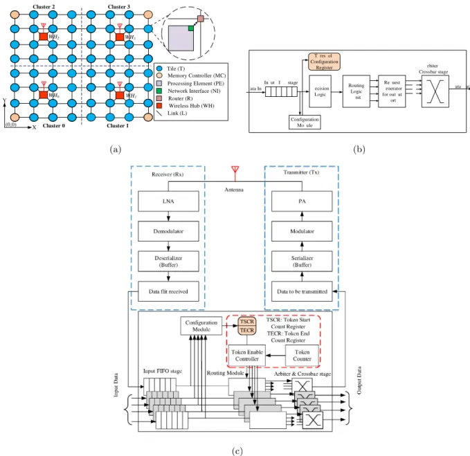
We consider a 8 × 8 WiNoC with four equally-sized clusters as shown in Figure 1(a). Each cluster consists of 16 nodes which are arranged in 4 × 4 fashion. Ev-ery cluster has a centrally placed wireless hub with a wireless interface (WI) providing inter-cluster wireless links. There are two types of routers in the WiNoC: normal routers that are connected to the processing elements (PEs) and hub routers that are connected to the wireless interfaces. Both types of routers perform uni-cast and broadcast communication. At the source router, a decision is made regarding use of wireless link for communication. Depending on the decision, packets can flow only through the normal routers or use both normal routers and wireless hubs. For broad-cast operation, the hubs are always used.
We use Time Division Multiple Access (TDMA) based token passing technique which divides token holding time for different hubs into time slots. For a given time slot, the hub which has the token will be able to transmit packet to other hub. Please note that other hubs which do not have the token will be able to receive the transmitted packet. This policy helps to avoid collision between different hubs. In our work, the packets first arrive at a hub to be trans-mitted but they may need to wait for the availability of the token. Once the hub is ready to transmit, it sends the packets. Currently we do not use any ac-knowledgment to send packets from a hub. So if a packet is lost during wireless transmission, the sender hub does not know about this. Please note that we use the term hub to indicate hub router containing the wireless transceiver. Further details of router ar-chitecture including hub router arar-chitecture are given in next section.
3.2
Normal Router architecture
We consider a 5-port router in our system architec-ture, which consists of North, South, East, West, and Local ports, respectively. Figure 1(b) shows a nor-mal router architecture. For ease of understanding, we only show a single input and output port. The routers are configurable and they are configured be-fore the start of normal operation. The Configuration Module receives configuration packets from all input ports except the local port and configures Threshold Configuration Register (TCR) of every input port of the router. When a normal packet arrives at the input FIFO, the Decision Logic (DL) decides if the packet must be routed through the wireless hub or through wired communication based on the TCR. Depending on the decision, it sends a request signal to the corre-sponding output port through the Routing Logic Unit (RLU) and later sends the packet when the output port is available. The RLU is responsible for routing packets for both wired and wireless communication. In case of wireless communication, the packets are routed to the hub router for wireless transmission.
We call the routers which are directly connected to the hub as hub connection (HC) router. These HC routers have a sixth port which is exclusively used to connect to the hub. That means in some routers, the Request Generator for output Port module has five out going signals instead of four as shown in Figure 1(b).
3.2.1 Routing Algorithm
Algorithm 1: Threshold based XY Routing
Input :Source Router Id, Destination Router Id Output :Output port for packet transmission Constants:Xdim = 8, Ydim = 8
1 Source Router Row = Source Router Id / Ydim 2 Source Router Column = Source Router Id % Xdim 3 Destination Router Row = Destination Router Id / Ydim 4 Destination Router Column = Destination Router Id %
Xdim
5 if((|Sour ce Rout er Row − Destination Rout er Row | +
|Sour ce Rout er Column − Dest inat ion Rout er Column |) ≥ T H) then
6 Packet transmission through wireless hub
7 else
8 Packet transmission through wired NoC
To route packets from source to destination node, we have used a threshold based XY routing algo-rithm similar to [28]. We assume that every router knows the topological information, such as size of the network (X and Y dimension) and number of wire-less Nodes. The head flit in the packet contains the source and destination address. First, the manhattan distance between the source and destination nodes is calculated. Algorithm 1 presents the threshold based XY routing strategy. If the manhattan distance be-tween the source and destination nodes is greater than a given threshold then the packet is routed using the wireless hub. Alternatively, it is routed through wired NoC. To route a packet through wireless hub, first it is routed to the HC router which sends it to the hub router. The source hub transmits the packet to its
WH2 WH3
WH0 WH1
Processing Element (PE) Network Interface (NI) Router (R) Tile (T) Memory Controller (MC) Link (L) X Y (0,0) Wireless Hub (WH) Cluster 0 Cluster 1 Cluster 2 Cluster 3 (a) Routing Logic nit ecision Logic Configuration Mo ule Re uest enerator for out ut ort In ut I stage rbiter Crossbar stage ata In ata ut T res ol Configuration Register (b) (c)
Figure 1: (a) 8 × 8 mesh NoC with 4 Wireless hubs in each cluster, (b) Normal router architecture and (c) Hub router architecture including the wireless transceiver portion.
destination hub using wireless transmission. There-after, the packet is routed to its destination. The methods to calculate the address of HC router are presented in Appendix A.
Broadcast Packets are communicated using
WHIRL routing algorithm [29]. The structure of
the head flit is modified to include a new tag called Communication Type (CT). If the CT is ‘1’ then the packet is a broadcast packet else uni-cast packet. First, the Decision Logic checks whether the packet is a broadcast or not. If broadcast packet, it is routed to its hub connection router and all other routers
in the cluster. Next, after receiving the packet,
the source hub transmits the packet to all other hubs present in the WiNoC. After the broadcast packet is received by an individual hub, the packet is communicated to each router of the cluster to which the hub is associated.
3.3
Hub Router architecture
Figure 1(c) shows the hub router architecture. Please note that the same input port structure is present in all input ports including the wireless receiver port (WRP). Only wireless transmitter port (WTP) side Arbiter and crossbar stage has signals from 4 other input ports but all other output ports (N, S, E and W) have only one connection from WRP input port. The reason is that packets entering the hub from all ports except WRP, want to send packet using wire-less communication through WTP but packet coming from wireless communication and entering from WRP input port, can go to any other output ports.
The hubs use token passing protocol to ensure fare share of the communication link usage because all of them use the same frequency. The Token counter is used to implement the token passing method which is incremented by 1 in each clock cycle and it becomes 0 after it expires to start counting again. The Token counter value is decided by the number of hubs and
where TCis the Token counter range, H is the number
of hubs and Tk is the duration for which the token is
hold by a hub. The Token Enable Controller enables all the Routing Modules of all input ports using the Token Start Count Register (TSCR) and Token End Count Register (TECR). TSCR and TECR are con-figured at the start of operation by the Configuration Module. These registers will store different values in each hub denoting equal division of the total to-ken distribution period which is same as the Toto-ken Counter range. In this way the hubs will have au-thority to use the wireless communication in round robin or any other manner as set by the TSCR and TECR. Packet ormation Mo ule Message I Message from PE Message ormation Mo ule Message to PE Packet I rom configuration mo ule of Router Packet from Router Packet to Router Configuration Table
Figure 2: Network interface architecture is shown connecting a PE and the Eject port of a router.
3.4
Network Interface (NI)
architec-ture
Figure 2 shows the Network interface (NI) architec-ture. The PE (processing element) sends messages to the NI where they are stored in the message FIFO. The Packet Formation Module forms packets using the Configuration table and messages from FIFO. It sends the packet to the Ejection port of the router when the port is free. The Configuration Module of the router configures the Configuration table when it receives configuration packet for this purpose. Please note that the PE does not configure anything includ-ing this table. The Message Formation Module forms messages using the Configuration Table and packets from the Eject port of the router. After that, it sends the messages to the PE when it is free to receive.
3.5
Threat model
Here we discuss the threat models considered in this work.
1. Denial of Service: In this attack, we isolate the hub(s) causing the WiNoC to behave like wired NoC without the benefit of wireless communi-cation. It is also possible that the packets will wait indefinitely for a hub causing complete dis-ruption of communication. Complete disdis-ruption of communication may happen due to congestion in normal routers because of waiting packets that want to flow through a hub.
2. Over-utilization of resources: In this attack, a resource like hub is utilized. This
over-reliance on a resource causes congestion in the WiNoC.
3. Thermal Attacks: This is a severe form of over-utilization attack. This attack causes hyper-activity of Hub Routers causing extreme power consumption and hot spots.
4. Data stealing: In this attack, uni-cast packets are maliciously converted to broadcast packets causing leakage of sensitive data to the attacker.
3.6
Global picture of attack scenarios
Figure 3: Two attack scenarios: (a) the host processor is compromised, and (b) an internal PE of the MPSoC is controlled by an attacker.
Here we discuss the global picture of two attack scenarios that can be used by an attacker to mali-ciously configure inside WiNoC to launch the attacks discussed later. Similar attack method was used in [30, 31] to launch attack in NoC. In the first scenario, we assume that the MPSoC using the WiNoC is con-nected to the outside world through a computing sys-tem (also called manager node), that is responsible for allocating and mapping applications from outside to this target system (refer Figure 3(a)). So the con-figuration happens as and when necessary just like a cluster computing or supercomputer system. An at-tacker can insert a malicious agent on this manager node first, which will then control the configuration of the WiNoC later or during runtime. In the sec-ond scenario, as shown in Figure 3(b), attacker will be allowed to run his/her applications on the MPSoC because of resource sharing on the same MPSoC. In this example, the attacker will be able to configure all the WiNoC routers from PE(1,0) if any security mechanism is not present. The attacker only needs to guess the address of the configuration register of each router and write the malicious data by trial and error method. Please note that the address space is not large if we consider memory mapped configuration register modification in each router of the WiNoC. Please also note that an attacker can use any one or both scenarios mentioned here to maliciously con-figure inside WiNoC. But depending on the configu-ration target, different types of attacks are possible which are discussed in more detail in next section.
4
New attacks against WiNoC
based system with
experimen-tal results
Here we describe various new attacks namely, Mali-cious Threshold Configuration (MTC) Attack, Dis-ruptive Token Passing (DTP) Attack, Data Steal-ing by Broadcast (DSB) Attack and Hybrid Attack
against a WiNoC based system. We also provide
the experimental setup and simulation results show-ing the effects of these attacks on the system.
4.1
Global simulation setup
The Wireless NoC architecture is modeled and sim-ulated using the cycle accurate Noxim 3.0 simulator [32]. We use Snipersim 6.1 [33] for full system sim-ulation of SPLASH2 [34] and PARSEC [35] bench-marks to generate the traces. These traces are fed into the Noxim simulator for performance evaluation of WiNoC in terms of network latency and through-put. The Noxim simulator also reports the number of packets transmitted by the wireless hub as hub uti-lization. The energy consumed by the hubs depends on the hub utility and calculated in accordance with [36]. The standard Noxim simulator is used for reg-ular WiNoC simulation. We modify the simulator to demonstrate the attack and also to show the ef-fectiveness of our proposed countermeasures against such attacks. The system specifications are presented in Table 1. We use wormhole routing and the input buffers of the routers are 8-flit long with buffer depth of 32 bits. In order to bring out characteristics of the WiNoC architecture in the presence of both compu-tation intensive and communication intensive work-loads, we have considered four SPLASH-2 [34] bench-marks (barnes, fmm, radiosity and raytrace) and two PARSEC [35] benchmarks (blackscholes and fluidan-imate). Please note that the simulation results given in this paper carry (A) and (C) extensions to denote under attack without countermeasure and under at-tack with countermeasure respectively.
4.2
Malicious Threshold
Configura-tion (MTC) Attack
As discussed in Section 3.2.1, routers use threshold based routing method. The threshold value T H is application as well as platform dependent. The map-ping of applications onto an NoC platform depends on number of PEs present in the platform. Next, based on the network traffic and communication pat-tern, the threshold is determined. To determine the threshold values for different applications, we have conducted a set of experiments with varying thresh-old values. From Figure 4, we observe that differ-ent applications achieve their best (i.e., minimum) latencies for different threshold values. So a config-urable threshold value will help to avoid congestion and hotspots. This value is configured in routers at the beginning of execution of the given application set. In the absence of any security measure, an
at-tacker can maliciously modify this configuration value in target router(s). In this case, two types of attack scenarios may occur: (1) MTC-DOR (Denial Of Re-source): The threshold value can be made very large causing abandonment of wireless hubs in the NoC i.e., denial of access of resource and (2) MTC-OU (Over-Utilization): The threshold value can be made very small causing all packets to travel only through wire-less hub. This causes over-utilization of the hubs and excessive power consumption.
bar nes blac ksch oles fmm fluid anim ate radios ity rayt race 15 20 25 30 Lat en cy (c y cl es )
Threshold=6 Threshold=8 Threshold=10
Figure 4: Latency under different threshold values for applications belonging to PARSEC and SPLASH2 benchmark suit.
4.2.1 Simulation Setup
We evaluate the WiNoC performance with attack (un-der both MTC-DOR and MTC-OU attacks) for dif-ferent traffic scenarios in terms of latency, wireless hub utilization and energy. In the Noxim simulator [32], both the router and the hub design are modified to implement the proposed work. For example, our proposed threshold based routing algorithm is imple-mented in the Noxim simulator. In real application of the WiNoC, the threshold value is provided by the user before starting the normal operation. Currently we assume the threshold T H value as 8 hops. Thresh-old configuration registers in normal routers (refer Figure 1(b)) are configured to 16 (greater than the maximum hop-count) and 0 to simulate MTC-DOR and MTC-OU attacks, respectively.
4.2.2 Analysis
Figure 5 shows run-time wireless hub utilization for both MTC-DOR and MTC-OU attacks. As shown in the figure, in MTC-DOR case, the utilization of wire-less hubs is zero. Hence, energy consumed by wirewire-less hubs are negligible (assuming all wireless hubs are in sleep mode when they are not in use to reduce the power consumption [15]). As a consequence, over-all performance will be affected as wireless hubs are underutilized. Also from Figure 5, we can see that in MTC-OU case, the average increase in hub uti-lization across all benchmarks is 4 times compared to normal case. As a result, the average increase in
Table 1: Simulation Setup
Architecture Component Configuration
System
CPU ALPHA ISA cores, out-of-order cores, 2.5GHz
L1 cache 64KB, 4-way, LRU policy, 64B line, 1-cycle latency
L2 cache 256KB, 8-way, LRU policy, 64B line, 10-cycle latency
Cache coherence protocol MESI
Network
Topology 8 × 8 Mesh
Routing Threshold based XY routing for uni-cast communicationWHIRL routing for broadcast communication
Pipeline 2 stages
Flit size and Packet size 32 bits and 8 flits
Workload PARSEC and Splash-2, Synthetic
energy consumption by wireless hubs for all applica-tions is 137.7% as shown in Figure 6. Next, we focus our attention to Figure 7. From the figure we can observe that there is a degradation in latency under both DOR and OU attacks. In MTC-DOR case, as none of the packets take the wireless route the advantage of WiNoC is not reflected. The increase in latency for MTC-DOR is 7.6% (on aver-age) compared to normal case. However, in MTC-OU case, as all the packets are routed though wireless hubs, there is congestion in the network and the la-tency becomes very high. For this simulation setup, we consider maximum latency till 100 clock cycles.
bar nes blac ksch oles fmm fluid anim ate rad iosity rayt race 0 0.5 1 W ir el es s Hu b Ut il iz at ion
Regular WiNoC MTC-DOR(A) MTC-OU(A)
Figure 5: MTC Attack: Wireless Hub Utilizations for different benchmark applications for both MTC-DOR and MTC-OU attacks.
4.3
Disruptive Token Passing (DTP)
Attack
In case of disruptive token passing (DTP) attack, an attacker maliciously configures TSCR and TECR in target hub(s) (refer Figure 1(c)). There are mainly 2 types of DTP attack: 1)DTP-DOS (Denial Of Ser-vice): the attacker can make the duration 0 caus-ing denial of service of a particular hub and 2)DTP-AHT (All Hubs holding Token): The duration can be made to the whole counter range for all hubs. This will make all the hubs holding the token all the time causing collisions and packet drops between different hub communications. This also increases the power consumption of the hubs.
barne s blac ksch oles fmm fluid anim ate rad iosity rayt race 1 1.5 2 2.5 3 W ir el es s Hu b E n er gy C on su m p ti on (µ J)
Regular WiNoC MTC-OU(A)
Figure 6: MTC Attack: Wireless Hub Energy Con-sumption for different benchmark applications for MTC-OU attack. bar nes blac ksch oles fmm fluid anim ate rad iosity rayt race 50 100 Lat en cy (c y cl es )
Regular WiNoC MTC-DOR(A) MTC-OU(A)
Figure 7: MTC Attack: Average Network Latency for different benchmark applications for both MTC-DOR and MTC-OU attacks.
4.3.1 Simulation Setup
We present the performance of WiNoC under both DTP-DOS and DTP-AHT attacks under the afore-mentioned traffic scenarios in terms of throughput, packet loss and wireless hub utilization. The token passing mechanism of Noxim simulator [32] is modi-fied to simulate both DTP-DOS and DTP-AHT
Count Register (TSCR) and Token End Count Reg-ister (TECR) are modified to implement the DTP attacks. 4.3.2 Analysis bar nes blac ksch oles fmm fluid anim ate rad iosity rayt race 0 0.5 1 W ir el es s Hu b Ut il iz at ion
Regular WiNoC DTP-DOS(A) DTP-AHT(A)
Figure 8: DTP Attack: Wireless Hub Utilizations for different benchmark applications for both DTP-DOS and DTP-AHT attacks.
bar nes blac ksch oles fmm fluid anim ate rad iosity rayt race 20 40 60 80 100 % of P ac ke t Los s
DTP-DOS(A) v/s Regular WiNoC DTP-AHT(A) v/s Regular WiNoC
Figure 9: DTP Attack: Packet Loss for
differ-ent benchmark applications for both DTP-DOS and DTP-AHT attacks.
The Wireless Hub Utilization for DTP attack is de-picted in Figure 8. For the DTP-DOS attack, the hub utilization is negligible as none of the hubs have the token and packet transmission from hubs are stopped. However, it can be observed that the hub utilization is 100% for DTP-AHT attack. As all hubs have the to-ken, they always remain active irrespective of packet transmission. This results in high energy consump-tion by the hubs. In our experiment, we found that the maximum hub energy to be 32.3µJ. In case of DTP-DOS, packets are directed towards the hub for wireless transmission. As no hub has token, these packets wait in their path causing congestion in the network. This results in packet loss which is the num-ber of packets that could not be injected into the sys-tem due to unavailability of buffer space. The aver-age packet loss for all the application is 94% in case of DTP-DOS attack. This is depicted in Figure 9.
bar nes blac ksch oles fmm fluid anim ate rad iosity rayt race 0 2 4 ·10−2 T h rou gh p u t (fl it s/c y cl e/I P )
Regular WiNoC DTP-DOS(A) DTP-AHT(A)
Figure 10: DTP Attack: Average Network Through-put for different benchmark applications for both DTP-DOS and DTP-AHT attacks.
Also, from the figure we observe that there is packet loss in case of DTP-AHT. The hubs operate in a half duplex mode i.e., a hub cannot transmit and receive at the same time. If all of them have the token, then all are configured as transmitter. Thus, packets will be transmitted from the source hub but will not be received at the destination hub. The average percent-age of packet loss is 27% for DTP-AHT compared to regular WiNoC. The packet loss during both attacks also cause average network throughput drop (more for DTP-DOS than DTP-AHT) compared to regular WiNoC. The drop in throughput for all applications, on average is 23.1x and 1.23x for DOS and DTP-AHT, respectively. This is depicted in Figure 10.
4.4
Data Stealing by Broadcast (DSB)
Attack
In case of secure communication inside the WiNoC, the wireless communication is not used because all the hubs along with the intended receiver hub can snoop into the packets. This special communication is only possible because the packets carry a type bit that is recognized by all routers. The packets are formed inside network interface of the sender PE us-ing a configuration table (refer Figure 2) which trans-lates the messages received from the PE to a set of packets. This table is also configured at the beginning of WiNoC operation and can be maliciously mod-ified by an attacker. The attacker can modify the packet type from special to normal and from uni-cast to broadcast. In case of DSB attack, the packets will be transmitted to all the routers instead of a partic-ular destination router.
Note that, the term PE also denotes the memory controller that connects the external memory with the WiNoC fabric. In a shared memory system, the PE (processing element) that is responsible for encryp-tion or decrypencryp-tion for secure communicaencryp-tion, loads the secret key from external memory. Even if the PE uses local memory to store the key and performs se-curity operations, it needs to load from memory in a regular basis because in a practical system the keys
are not fixed for a long time. The attacker can mali-ciously modify the Configuration Table inside the NI of the router connecting the memory controller. In this way, the attacker will obtain the packets when-ever the secure PE loads the key. Please note that this attack is possible because it does not depend on any software vulnerability or OS vulnerability but uses a network level attack. Also note that the DSB attack can target any sensitive data (for example, any per-sonal data) and not only secret key.
4.4.1 Simulation Setup
For experimentation, we assume that 4 Memory Con-trollers (MCs) are present in the WiNoC at the 4 cor-ners (refer Figure 1(a)) i.e., PE0,0, PE0,7, PE7,0 and
PE7,7. We assume that a secret key is pre-loaded
se-curely to the memory connected to PE0,0. This secret
key is needed to decrypt the encrypted data available
at the memory connected to PE7,0. In case of attack,
all the uni-cast packets injected into the WiNoC from
PE0,0are converted to broadcast by changing the CT
tag in packets from ‘0’ to ‘1’.
4.4.2 Analysis
Figure 11 shows router utility factor (RUF) for all the routers present in the network. During normal
oper-ation (i.e., without any attack), the PE7,4 initiates a
request and sends it to the PE0,0. PE0,0 processes
the request and sends the requested key to the
ini-tiator PE. On receiving the key, the PE7,4 uses it to
retrieve information from the PE7,0. This is depicted
in Figures 11(a) and 11(b), respectively. Next, we
launch an attack on the NI connecting the PE0,0and
r out er0,0, and the packet which was meant for PE7,4
is converted into a broadcast packet. So, the packet is broadcasted to all the PEs present in the network. Now, every PE has the key and using this key they can
access the data through PE7,0. In this example, PE2,2
is a malicious PE. Thus, after receiving the key, PE2,2
retrieves the encrypted data through PE7,0. This is
depicted in Figures 11(c) and 11(d) respectively. Fig-ure 11(d) also shows the data transmission between PE7,4and PE7,0apart from the data stealing by PE2,2.
4.5
Hybrid Attack
An attacker combines different attacks to launch a hybrid attack. For example, the attacker can com-bine MTC-OU attack where all communications be-come wireless and DTP-AHT attack when all hubs are active all the time. Worst case situation results in a thermal attack, where the attacker combines DSB (targeting all or a group of routers’ network inter-faces) with MTC-OU and DTP-AHT. In that case, all the hubs are sending to all other hubs increasing the packet flow and power consumption in the whole chip.
4.5.1 Simulation Setup
We use the PARSEC benchmark application “flu-idaminate" to evaluate the thermal attack on the
WiNoC shown in Figure 1(a). For this purpose, we configure the normal routers for MTC-OU attack, hub routers for DTP-AHT attack and NIs for DSB attack. The power consumption of the routers, the hubs, and the PEs are estimated and are fed to the Hotspot tool [37] to calculate the temperature of the chip. The hub power is considered to be similar to [36] and depends on the hub utility. Similarly, we calculate RUFs for all the routers present in the WiNoC. These values are fed to the Orion tool [38] to calculate individual router power. The average power consumption of a PE is extracted from Snipersim [33]. In addition to the power of the individual components, Hotspot also requires floor-plan of the chip. In this paper, we con-sider a chip of 20 mm × 20 mm, consisting of 64 cores arranged in 8 × 8 mesh structure. We use the grid model of HotSpot with a grid size of 1024 × 1024.
4.5.2 Analysis
The temperature profiles of the chip during normal operation and thermal attack are given in Figures 12(a) and 12(b) respectively. During normal oper-ation, we observe a relatively uniform temperature profile for the entire chip. This is because the util-ity of both the routers and hubs are quite low for the “fluidaminate" application specific traffic. The zoomed portion in Figure 12(a) shows tiles associ-ated with a hub with 2% utility factor. Next, during thermal attack, the overall chip temperature is high, with the tiles associated with wireless hubs exhibiting the highest temperature. Due to the combination of MTC-OU and DTP-AHT attacks, the overall energy consumption of wireless hubs are significantly higher compared to regular WiNoC. Also, DSB attack forces uni-cast packets to broadcast. Thus, the number of packets processed by the routers increases, which in turn increases the router power consumption. This rise in temperature profile of the chip may degrade the system performance and in extreme cases leads to system failure.
5
Countermeasures
and
com-parison with related works
In this Section, we discuss various countermeasures against the attacks considered in this paper. We also discuss the comparison with related works.
5.1
Source Destination (SD)
check-ing mechanism:
countermeasure
against MTC Attack
We implement the Source Destination (SD) checking mechanism as given in Algorithm 2 in Decision logic (refer Figure 1(b)) before performing the threshold based routing in RLU. SD mechanism is used to con-ditionally bypass the threshold based method and di-rectly use the Routing logic unit for XY routing.
Algorithm 2 compares the manhattan distance be-tween the source and destination routers and their corresponding hub-connection routers with distance
Routers Routers R ou te r Ut il it y F ac to r (R UF) 0.25 0.50 0.75 0 1 2 3 4 5 6 7 0 1 23 4 5 6 7 (a) Routers Routers R ou te r Ut il it y F ac to r (R UF) 0.25 0.50 0.75 0 1 2 3 4 5 6 7 0 1 2 3 4 5 6 7 (b) Routers Routers R ou te r Ut il it y F ac to r (R UF) 0.25 0.50 0.75 0 1 2 3 4 5 6 7 0 1 2 3 4 5 6 7 (c) Routers Routers R ou te r Ut il it y F ac to r (R UF) 0.25 0.50 0.75 0 1 2 3 4 5 6 7 0 1 2 3 4 5 6 7 (d)
Figure 11: Normal execution case : (a) key transfer and (b) data transaction. Under attack case: (c) key transfer and (d) data transaction.
Figure 12: Temperature profile of the chip under (a) normal operation and (b) under thermal attack.
Algorithm 2:Source Destination Checking
Input :Source Router id, Destination Router id, Source HC router id, Destination HC router id Output :Decision to use threshold based routing Constants:Xdim = 8, Ydim = 8, hub_to_hub_distance =
1
1 Source Router Row = Source Router id / Ydim 2 Source Router Column = Source Router id % Xdim 3 Destination Router Row = Destination Router id / Ydim 4 Destination Router Column = Destination Router id %
Xdim
5 Source HC router Row = Source HC router id / Ydim 6 Source HC router Column = Source HC router id % Xdim 7 Destination HC router Row = Destination HC router id /
Ydim
8 Destination HC router Column = Destination HC router id
% Xdim
9 if(( |Sour ce Rout er Row − Destination Rout er Row | + |Sour ce Rout er Column − Dest inat ion Rout er Column |) ≥ ( |Sour ce Rout er Row − Sour ce HC r out er Row | + |Sour ce Rout er Column − Sour ce H C r out er Column | + |Dest inat ion Rout er Row − Dest inat ion H C r out er Row |+ |Dest inat ion Rout er C olumn −
Dest inat ion H C r out er C olumn | + hub_t o_hub_dist ance) then
10 use wired XY routing algorithm
11 else
12 use threshold based XY routing algorithm
13 end
between source and destination routers. If the later is greater, then the packet is transmitted using wired communication. However, if the former is greater then it is compared with the threshold T H. This method helps to stop the flow of all packets towards the hubs and helps to counter the MTC-OU attack.
5.1.1 Simulation Setup
To implement the countermeasure for MTC attack, we have modified the routing algorithm present in the Noxim simulator. We use Algorithm 2 before evoking Algorithm 1 for routing packets from the source to destination node. As defined in Section 3.2.1, the source and destination addresses are obtained from the head flit of the packet. Next, Algorithms 3 and 4
from Appendix A are invoked to calculate the source and destination cluster ids and sub-cluster ids. This data is used to calculate the position of HC routers for source and destination nodes using Algorithm 5 given in Appendix A. These data are given as input to Algorithm 2, which determines the use of wireless hub for packet transmission.
5.1.2 Analysis bar nes blac ksch oles fmm fluid anim ate rad iosity rayt race 0.2 0.4 0.6 0.8 1 W ir el es s Hu b Ut il iz at ion MTC-OU(A) MTC-OU(C)
Figure 13: MTC Attack: Wireless Hub
Utiliza-tions for different benchmark applicaUtiliza-tions without and with countermeasure under MTC-OU attack.
The source destination checking mechanism helps to reduce the wireless hub utilization caused by MTC-OU attack as shown in Figure 13. The figure shows a 49% decrease (on average) in wireless hub utiliza-tion under MTC-OU attack when countermeasure is present. The energy consumption by the hubs also decreases (on average 38%) due to the decrease in wireless hub utilization in the presence of proposed countermeasure. This is depicted in Figure 14. Dur-ing normal operation, the threshold is set to 8 hops. In case of MTC-OU attack, this value is changed to zero causing all the packets to flow through the wire-less route. Using our SD countermeasure technique, we restrict the packet flow using the condition present in Algorithm 2. Therefore, there is an obvious im-provement in average network latency in presence of proposed countermeasure under MTC-OU attack case as shown in Figure 15.
bar nes blac ksch oles fmm fluid anim ate rad iosity rayt race 1.5 2 2.5 3 W ir el es s Hu b E n er gy C on su m p ti on (µ J) MTC-OU(A) MTC-OU(C)
Figure 14: MTC Attack: Wireless Hub Energy Con-sumption for different benchmark applications with-out and with countermeasure under MTC-OU attack.
bar nes blac ksch oles fmm fluid anim ate rad iosity rayt race 50 100 Lat en cy (c y cl es ) MTC-OU(A) MTC-OU(C)
Figure 15: MTC Attack: Average Network Latency for different benchmark applications without and with countermeasure under MTC-OU attack.
5.2
Detour mechanism:
countermea-sure against DTP Attack
We propose a new wireless hub access mechanism in the WiNoC. The DTP-DOS attack is detected by in-troducing a token wait counter (TWC) in each hub. TWC is incremented by 1 at each clock cycle if the token is not enabled. When the token is enabled in the hub, TWC is reset. TWC starts counting again when the token is disabled. To detect DTP-DOS at-tack, we check the most significant bit (MSB) of the TWC. If the MSB is 1 then the hub is under DTP-DOS attack because TWC counted for many clock cycles without the token. To detect the DTP-AHT attack, we have introduced two counters in the trans-mitter and receiver sections of the hub. These are Packet Transmission Counter (PTC) and Packet Re-ception Counter (PRC). Whenever a hub transmits a flit the PTC is incremented by one, on the other hand whenever a hub receives a flit the PRC is incremented by one. Also, after a receiver hub receives the tail flit, it sends an acknowledgment message to the transmit-ter hub. This is a self generated single flit packet.
We keep two checks for detection of DTP-AHT
at-tack. First, we check if the 4t h
bit of PTC is ‘1’ or ‘0’.
We select the 4t h
bit of PTC because 2 packets (16 flits) have been considered as threshold. This can be modified depending on the requirement of the user.
Next, if the 4t h bit is ‘1’, we check the PRC is all
zero or not. If PRC is all zero, then the hub is under DTP-AHT attack. In the above mentioned mecha-nisms, if an attack is detected in the hub, the hub is switched off. A signal is sent to the hub connection routers in the local cluster (the cluster in which the hub belongs) informing the unavailability of the hub for packet transmission. Packets in the hub connec-tion router awaiting for wireless transmission through the hub are re-directed towards the destination node using wired NoC. This process is implemented by us-ing a detour based routus-ing mechanism implemented in the Routing Logic Unit in the HC routers. The flowchart for this detour based routing is shown in Figure 16. Please note that ‘Dest_dst’ denotes the manhattan distance between the source and destina-tion routers. Source Router Is wireless hub available? Destination Router Is Dest_ dst > TH? Yes
Yes Routing using wireless hub
Routing using wire line Routing using wire
line to HC router
No No
Figure 16: Flowchart of detour based routing mecha-nism.
5.2.1 Simulation Setup
We have modified the hub architecture in Noxim sim-ulator to detect the attacks and implement the coun-termeasures for DTP-DOS and DTP-AHT attacks. We have added TWC in hubs to get the wait time be-fore its token is enabled. In transmitter and receiver sections of the hub, two counters (PTC and PRC) have been implemented to count the number of trans-mitted and received flits. A new signal which indi-cates the availability of the hub is introduced between the hub and the respective hub connection routers. Also, the detour based routing algorithm for packet transmission in case of attack is incorporated in the
Noxim.
5.2.2 Analysis
Our proposed countermeasures against DTP attacks help to reduce the packet loss. Thus, in presence of proposed countermeasures, the throughput of the system is improved by 1.21x and 23x under DTP-AHT (refer Figure 17(a)) and DTP-DOS (refer Figure 17(b)) attacks respectively. Next, we focus our atten-tion to the average network latency. As the hubs are switched off, all packets are communicated by wired routes. In this situation, the advantages of wireless NoC compared to wired NoC cease to exist. Thus there is a performance degradation under DTP at-tacks in presence of proposed countermeasures com-pared to regular WiNoC without any attack, as shown in Figure 18. The figure shows that the average la-tency increase for all the benchmarks with our coun-termeasures under DTP-DOS and DTP-AHT attacks are 14.65% and 14.23% respectively, compared to reg-ular WiNoC.
5.3
Countermeasures
against
DSB
and hybrid Attacks
If an attacker launches a hybrid attack combining DTP-DOS and MTC-OU attacks, we need to combine both countermeasures (Source destination checking and detour mechanism). Figure 19 shows the average network latency for different benchmark applications under hybrid attack with combined countermeasure in comparison with individual countermeasures. The combined countermeasure shows 9.46% and 24.55% degradation in latency compared to the countermea-sure against MTC-OU and DTP-DOS attacks respec-tively. This is because countermeasure against MTC-OU restricts the flow checking mechanism defined by Algorithm 2. However, the number of packets flowing toward the wireless hub increases as the predefined threshold is altered to zero by the attacker. Next, a bypass routing mechanism presented in Figure 16 is used to route the packets to their destination using the wired NoC. This is because as a countermeasure against DTP-DOS, the wireless hubs are switched-off. Hence, the latency increases when two countermea-sures are implemented together. But note that the extra overhead is comparatively small if we consider the protection against the hybrid attack.
All the attacks considered in this paper are mainly launched by taking advantage of insecure router con-figuration method. There are many configurable por-tions in a WiNoC based system. As a countermea-sure, we need to ensure that only trusted configu-ration source is allowed to configure both types of routers (normal and hub) and various parts of those routers. Existing source authentication methods like [39] can help to implement lightweight countermea-sures in a security critical WiNoC system. In this ex-isting solution, the authenticity of the configuration source is first checked before it is allowed to config-ure a destination. Various watermarking techniques, a stream authentication method and combinations of
these methods are used to transfer source authenti-cation information to destination where it is checked before starting the configuration.
In addition to that, we can ensure that a secure core only accesses a fixed memory controller which has pre-shared keys with it and it uses existing cryp-tographic algorithms like AES to encrypt the packet contents before sending it to the secure core. In this way, only the secure core can decrypt the contents and an attacker cannot get the content even if he/she got the packets in some manner. Please note that here, we do not assume that all the PEs or all the mem-ory controllers use encryption to hide contents of the packets. This is necessary to limit the overhead as-sociated with symmetric cipher like AES impacting total performance of the system when most portion of it may not require such level of security.
Even with cryptographic solutions, an attacker can try to access the memory by requesting read or write requests to the memory controller. Even if the at-tacker does not know the secret key, he/she can mod-ify the memory contents with garbage values by per-forming write operation. As a countermeasure we need a memory access control method that can en-sure that an attacker cannot access the memory to perform illegal tasks. Authors in [40] have used Role Based Access Control (RBAC) model to implement memory access control and a WiNoC based system can benefit from this solution. In this solution, every packet has a role id and every role has distinct per-mission to access a memory location and/or perform some task. Here an attacker cannot access a memory without obtaining the correct role through a secure authentication method.
5.4
Comparison with related works
Authors in [2] have considered DOS attack by inten-tional violation of collision prevention measures by attacker, Spoofing attack by giving false identity of attacker as legitimate source and Eavesdropping at-tack during broadcast operation by a source. They propose to use stream cipher called Py to protect from eavesdropping attack and it causes 5 cycles of latency overhead (46% increase over the unencrypted delay at 64 Gbps). In our case, we only consider specialized attacks which are specific to a WiNoC based system. The attack methods given in [2] are not realistic be-cause the Hardware Trojan that is assumed to be-cause all the attacks can also modify the behavior of their proposed countermeasures. In our case, we provide much more realistic attack methods and also show results using various benchmark applications to show their effects. We also provide the countermeasures that are resilient to these attacks.
Authors in [3] have also considered spoofing, re-play, and message modification attacks. Replay at-tack happens by repeating valid packets which causes false operation and modification attack happens by altering the content of messages sent by legitimate senders. They assume that there is a fraudulent de-vice within the wireless coverage area which is tuned at the target wireless frequency spectrum. This
de-barne s blac ksch oles fmm fluid anim ate radios ity rayt race 1 2 3 4 ·10− 2 T h rou gh p u t (fl it s/c y cl e/I P ) DTP-AHT(A) DTP-AHT(C) (a) barne s blac ksch oles fmm fluid anim ate radios ity rayt race 0 2 4 ·10− 2 T h rou gh p u t (fl it s/c y cl e/I P ) DTP-DOS(A) DTP-DOS(C) (b)
Figure 17: DTP Attack: Average Network Throughput for different benchmark applications under (a) DTP-AHT and (b) DTP-DOS attacks for both without and with countermeasures.
Table 2: Summary of comparison with related works
[2] [4] [3] Our work
Attack types DOS, Spoofing, DOS Spoofing, Replay, DOS (MTC-DOR,
Eavesdropping Message modification DTP-DOS, DTP-AHT),
Overutilization (MTC-OU), Data stealing (DSB)
Attack method Hardware Trojan Hardware Trojan Fradulent device placed Malicious configuration
within wireless coverage area
Performance overhead 46% at 64 Gbps Depends on the More than 30% No degradation
due to derived topology
countermeasure during which is depended
normal operation on application
barne s blac ksch oles fmm fluid anim ate radios ity rayt race 15 20 25 Lat en cy (c y cl es )
Regular WiNoC DTP-DOS(C) DTP-AHT(C)
Figure 18: DTP Attack: Average Network
La-tency for different benchmark applications for regular WiNoC without any attack and also under DTP-DOS and DTP-AHT attacks in presence of proposed coun-termeasures.
vice interferes the communication in the WiNoC to launch attacks. They have proposed a hash based countermeasure to protect from the attacks. Please note that this solution is applied to all the packets and causes more than 30% performance overhead com-pared to the system without any security measures. We also use a countermeasure for source authentica-tion [39] but that is used before starting normal
oper-barne s blac ksch oles fmm fluid anim ate radios ity rayt race 20 30 Lat en cy (c y cl es )
MTC-OU(C) DTP-DOS(C) Combined(C)
Figure 19: Hybrid Attack (MTC-OU and DTP-DOS): Average Network Latency for different benchmark ap-plications under hybrid attack with combined coun-termeasure in comparison with individual counter-measures.
ation of the WiNoC and hence does not cause any performance degradation. Our additional counter-measures of memory access control [40] do not cause any performance degradation and only the encryption based countermeasure mentioned in Section 5.3 will cause performance issues but it is limited only to the secure core communicating with a specific memory controller.
Authors in [4] have considered DOS attack due to Hardware Trojan. They have not proposed any coun-termeasure but have proposed to minimize the effect of attack to some extent by using a new network topology which is dependent on the application run-ning in the system. That means the WiNoC cannot run any other application other than the one consid-ered during design. Otherwise the DOS attack resis-tance will not be effective. Our countermeasures are not application dependent and this allows the WiNoC to facilitate parallel applications to run in the system. A summary of comparison with related works is given in Table 2.
6
Conclusions
In this paper, we have described Malicious Thresh-old Configuration (MTC) Attack, Disruptive Token Passing (DTP) Attack, Data Stealing by Broadcast (DSB) Attack and Hybrid Attack against the WiNoC based system. We have also provided the experimen-tal setup and simulation results showing the effects of these attacks on the system. We have shown that MTC-DOR attack causes wireless hub utilization to be 0 and MTC-OU attack increases it around 4 times compared to regular WiNoC. Also MTC-OU attack increases average network latency by many orders of magnitude compared to regular WiNoC causing over-all system performance degradation. We have also shown that the wireless hub utilization becomes 0 for DTP-DOS attack and around 100% for DTP-AHT attack. The network throughput drops around 23.1x and 1.23x under DTP-DOS and DTP-AHT attacks respectively. In addition, we have provided counter-measures that can protect from these attacks without causing considerable performance overhead of the sys-tem. Our proposed countermeasure against MTC-OU attack i.e., Source Destination checking mechanism decreases wireless hub utilization by 49% and net-work latency by many orders of magnitude compared to without countermeasure, causing system perfor-mance improvement. Our proposed countermeasure against DTP attacks i.e., detour mechanism improves the network throughout by 1.21x and 23x under DTP-AHT and DTP-DOS attacks respectively compared to without countermeasure cases.
In future, we would like to consider hardware tro-jans which were out of scope of this paper. We will also consider FDMA and CDMA techniques for at-tacks and their countermeasures in our future work.
References
[1] S. Evain and J. Diguet, “From noc security analysis to design solutions,” in IEEE Workshop on Signal Pro-cessing Systems Design & Implementation, ser. VL-SISP, Nov 2005.
[2] B. Lebiednik, S. Abadal, H. Kwon, and T. Krishna, “Architecting a secure wireless network-on-chip,” in 2018 Twelfth IEEE/ACM International Symposium on Networks-on-Chip (NOCS), 2018.
[3] F. Pereñíguez García and J. L. Abellán, “Secure com-munications in wireless network-on-chips,” in
Pro-ceedings of the 2Nd International Workshop on Ad-vanced Interconnect Solutions and Technologies for Emerging Computing Systems, ser. AISTECS ’17, 2017.
[4] A. Ganguly, M. Y. Ahmed, and A. Vidapalapati, “A denial-of-service resilient wireless noc architec-ture,” in Proceedings of the Great Lakes Symposium on VLSI, ser. GLSVLSI ’12, 2012.
[5] P. P. Pande, A. Ganguly, K. Chang, and C. Teuscher, “Hybrid wireless network on chip: A new paradigm in multi-core design,” in 2009 2nd International Work-shop on Network on Chip Architectures, Dec 2009, pp. 71–76.
[6] C. Wang, W. Hu, and N. Bagherzadeh, “A wire-less network-on-chip design for multicore platforms,” in 2011 19th International Euromicro Conference on Parallel, Distributed and Network-Based Processing, 2011.
[7] S.-B. Lee, S.-W. Tam, I. Pefkianakis, S. Lu, M. F. Chang, C. Guo, G. Reinman, C. Peng, M. Naik, L. Zhang, and J. Cong, “A scalable micro wireless interconnect structure for cmps,” in Proceedings of the 15th Annual International Conference on Mobile Computing and Networking, ser. MobiCom ’09, 2009. [8] S. Deb, K. Chang, X. Yu, S. P. Sah, M. Cosic, A. Ganguly, P. P. Pande, B. Belzer, and D. Heo, “Design of an energy-efficient cmos-compatible noc architecture with millimeter-wave wireless intercon-nects,” IEEE Transactions on Computers, vol. 62, no. 12, 2013.
[9] A. Ganguly, K. Chang, S. Deb, P. P. Pande, B. Belzer, and C. Teuscher, “Scalable hybrid wireless network-on-chip architectures for multicore systems,” IEEE Transactions on Computers, vol. 60, no. 10, 2011.
[10] A. Ganguly, P. Wettin, K. Chang, and P. Pande, “Complex network inspired fault-tolerant noc archi-tectures with wireless links,” in Proceedings of the Fifth ACM/IEEE International Symposium, 2011. [11] D. DiTomaso, A. Kodi, S. Kaya, and D. Matolak,
“iwise: Inter-router wireless scalable express channels for network-on-chips (nocs) architecture,” in 2011 IEEE 19th Annual Symposium on High Performance Interconnects, 2011.
[12] M. Alaei and F. Yazdanpanah, “H2wnoc: A honey-comb hardware-efficient wireless network-on-chip ar-chitecture,” Nano Communication Networks, vol. 19, pp. 119 – 133, 2019.
[13] A. Vidapalapati, V. Vijayakumaran, A. Ganguly, and A. Kwasinski, “Noc architectures with adaptive code division multiple access based wireless links,” in 2012 IEEE International Symposium on Circuits and Sys-tems (ISCAS), May 2012, pp. 636–639.
[14] R. Wu, Y. Wang, and D. Zhao, “A low-cost deadlock-free design of minimal-table rerouted xy-routing for irregular wireless nocs,” in 2010 Fourth ACM/IEEE International Symposium on Networks-on-Chip, 2010.
[15] H. K. Mondal, S. H. Gade, S. Kaushik, and S. Deb, “Adaptive multi-voltage scaling with uti-lization prediction for energy-efficient wireless noc,” IEEE Transactions on Sustainable Computing, vol. 2, no. 4, 2017.
[16] A. Asaduzzaman, K. K. Chidella, and D. Vardha, “An energy-efficient directory based multicore archi-tecture with wireless routers to minimize the com-munication latency,” IEEE Transactions on Parallel and Distributed Systems, vol. 28, no. 2, pp. 374–385, Feb 2017.
[17] D. Zhao, Y. Wang, J. Li, and T. Kikkawa, “De-sign of multi-channel wireless noc to improve
on-chip communication capacity!” in Proceedings of
the Fifth ACM/IEEE International Symposium, May 2011, pp. 177–184.
[18] I. E. Masri, T. Le Gouguec, P. Martin, R. Allanic, and C. Quendo, “Integrated dipole antennas and propagation channel on silicon in ka band for winoc applications,” in 2018 IEEE 22nd Workshop on Sig-nal and Power Integrity (SPI), May 2018, pp. 1–4. [19] M. O. Agyeman, Q. Vien, and T. Mak, “An
analyt-ical channel model for emerging wireless networks-on-chip,” in 2016 IEEE Intl Conference on Computa-tional Science and Engineering (CSE) and IEEE Intl Conference on Embedded and Ubiquitous Comput-ing (EUC) and 15th Intl Symposium on Distributed Computing and Applications for Business Engineer-ing (DCABES), Aug 2016, pp. 9–15.
[20] J. O. Sosa, O. Sentieys, and C. Roland, “A diver-sity scheme to enhance the reliability of wireless noc in multipath channel environment,” in 2018 Twelfth IEEE/ACM International Symposium on Networks-on-Chip (NOCS), Oct 2018, pp. 1–8.
[21] D. W. Matolak, S. Kaya, and A. Kodi, “Channel mod-eling for wireless networks-on-chips,” IEEE Commu-nications Magazine, vol. 51, no. 6, pp. 180–186, June 2013.
[22] X. Yu, S. P. Sah, S. Deb, P. P. Pande, B. Belzer, and D. Heo, “A wideband body-enabled millimeter-wave transceiver for wireless network-on-chip,” in 2011 IEEE 54th International Midwest Symposium on Circuits and Systems (MWSCAS), Aug 2011, pp. 1–4.
[23] S. H. Gade, S. Garg, and S. Deb, “Ofdm based high data rate, fading resilient transceiver for wireless networks-on-chip,” in 2017 IEEE Computer Society Annual Symposium on VLSI (ISVLSI), July 2017, pp. 483–488.
[24] J. Ortiz Sosa, O. Sentieys, and C. Roland, “Adap-tive transceiver for wireless noc to enhance mul-ticast/unicast communication scenarios,” in 2019 IEEE Computer Society Annual Symposium on VLSI (ISVLSI), July 2019, pp. 592–597.
[25] A. Mineo, M. Palesi, G. Ascia, and V. Catania, “Run-time tunable transmitting power technique in mm-wave winoc architectures,” IEEE Transactions on Very Large Scale Integration (VLSI) Systems, vol. 24, no. 4, pp. 1535–1545, April 2016.
[26] X. Yu, H. Rashtian, S. Mirabbasi, P. P. Pande, and D. Heo, “An 18.7-gb/s 60-ghz ook demodulator in 65-nm cmos for wireless network-on-chip,” IEEE Trans-actions on Circuits and Systems I: Regular Papers, vol. 62, no. 3, pp. 799–806, March 2015.
[27] S. Deb, A. Ganguly, P. P. Pande, B. Belzer, and D. Heo, “Wireless noc as interconnection backbone for multicore chips: Promises and challenges,” IEEE Journal on Emerging and Selected Topics in Circuits and Systems, vol. 2, no. 2, 2012.
[28] H. K. Mondal, R. C. Cataldo, C. A. Missio Marcon, K. Martin, S. Deb, and J. Diguet, “Broadcast- and power-aware wireless noc for barrier synchronization in parallel computing,” in 2018 31st IEEE Interna-tional System-on-Chip Conference (SOCC), 2018. [29] T. Krishna, L.-S. Peh, B. M. Beckmann, and S. K.
Reinhardt, “Towards the ideal on-chip fabric for 1-to-many and 1-to-many-to-1 communication,” in Proceedings of the 44th Annual IEEE/ACM International Sym-posium on Microarchitecture, ser. MICRO-44, 2011. [30] A. K. Biswas, S. K. Nandy, and R. Narayan,
“Network-on-chip router attacks and their prevention in mp-socs with multiple trusted execution environ-ments,” in 2015 IEEE International Conference on Electronics, Computing and Communication Tech-nologies (CONECCT), July 2015, pp. 1–6.
[31] A. K. Biswas, S. K. Nandy, and R. Narayan, “Router attack toward noc-enabled mpsoc and monitoring countermeasures against such threat,” Circuits, Sys-tems, and Signal Processing, vol. 34, no. 10, pp. 3241– 3290, Oct 2015.
[32] V. Catania, A. Mineo, S. Monteleone, M. Palesi, and D. Patti, “Improving energy efficiency in wire-less network-on-chip architectures,” ACM Journal on Emerging Technologies in Computing Systems, vol. 14, no. 1, 2017.
[33] T. E. Carlson, W. Heirman, S. Eyerman, I. Hur, and L. Eeckhout, “An evaluation of high-level mechanistic core models,” ACM Transactions on Architecture and Code Optimization (TACO), 2014.
[34] S. C. Woo, M. Ohara, E. Torrie, J. P. Singh, and A. Gupta, “The splash-2 programs: Characterization and methodological considerations,” in Proceedings of the 22Nd Annual International Symposium on Com-puter Architecture, ser. ISCA ’95, 1995.
[35] C. Bienia, “Benchmarking modern multiprocessors,” Ph.D. dissertation, Princeton University, January 2011.
[36] X. Yu, J. Baylon, P. Wettin, D. Heo, P. P. Pande, and S. Mirabbasi, “Architecture and design of multi-channel millimeter-wave wireless noc,” IEEE Design Test, vol. 31, no. 6, 2014.
[37] W. Huang, S. Ghosh, S. Velusamy, K. Sankara-narayanan, K. Skadron, and M. Stan, “Hotspot: a compact thermal modeling methodology for early-stage vlsi design,” Very Large Scale Integration (VLSI) Systems, IEEE Transactions on, vol. 14, no. 5, 2006.
[38] A. Kahng, B. Li, L.-S. Peh, and K. Samadi, “Orion 2.0: A fast and accurate noc power and area model for early-stage design space exploration,” in Design, Automation Test in Europe Conference Exhibition, 2009. DATE ’09., 2009.
[39] A. K. Biswas, “Source authentication techniques for network-on-chip router configuration packets,” J. Emerg. Technol. Comput. Syst., vol. 13, no. 2, Nov. 2016.
[40] “Role based shared memory access control mecha-nisms in noc based mp-soc,” Nano Communication Networks, vol. 7.
A
PPENDIXA
M
ETHODS TO CALCULATE THEH
UBC
ONNEC-TION ROUTER POSI-TION
As already mentioned in Section 3, each cluster has a centrally placed wireless interface connected to hub router. The hub router is connected to 4 hub connection (HC) routers. Also, a cluster (refer to Figure 1(a)) is di-vided into sub-clusters, where each sub-cluster consists of 4 routers (arranged in 2 ⇥ 2 mesh) with one HC router. Next, we present the method to calculate the position of HC routers. The head flit of the packet provides the source and destination router addresses. The addresses are used by Algorithms ?? and ?? to find the cluster and sub-cluster ids of the source and destination routers. The cluster and sub-cluster id of the respective routers are provided as inputs to Algorithm ?? which gives the corresponding HC router id. Please note that router ids can also be represented as router addresses where the former is an integer representation while the later is the binary representation of the same.
Algorithm 3: Find Cluster id
Input : Cluster Row Size, Cluster Column Size, Router id Output :Cluster id
Constants: Xdim = 8, Ydim = 8 1 Router Row = Router id / Ydim 2 Router Column = Router id % Xdim
3 ifRouter Row < Cluster Row Size and Router Column < Cluster Column
Size then
4 Cluster id = 0
5 else ifRouter Row < Cluster Row Size and Router Column Cluster
Column Size then
6 Cluster id = 1
7 else ifRouter Row Cluster Row Size and Router Column < Cluster
Column Size then
8 Cluster id = 2 9 else
10 Cluster id = 3
Algorithm 4: Find Sub-Cluster id
Input : Cluster id, Sub-Cluster Row Size, Sub-Cluster Column
Size, Router id
Output :Sub-Cluster id
Constants: Xdim = 8, Ydim = 8 1 Router Row = Router id / Ydim 2 Router Column = Router id % Xdim
3 xstart = (Cluster id / Sub-Cluster Size) * Cluster Row Size 4 ystart = (Cluster id % Sub-Cluster Size) * Cluster Column Size 5 if((Router Column xstart and Router Column < xstart + Sub-Cluster
Column Size) and (Router Row ystart and Router Row < ystart+ Sub-Cluster Column Size)) then
6 Sub-Cluster id = 0
7 else if((Router Column xstart + Sub-Cluster Column Size) and (Router
Row ystart and Router Row < ystart + Sub-Cluster Column Size))
then
8 Sub-Cluster id = 1
9 else if((Router Column xstart and Router Column < xstart +
Sub-Cluster Column Size) and (Router Row ystart + Sub-Cluster Column Size)) then
10 Sub-Cluster id = 2 11 else
12 Sub-Cluster id = 3
Algorithm 5: Calculation of position of hub con-nection router (hcr)
Input : Cluster id, Cluster Row Size, Cluster Column Size,
Sub-Cluster id
Output :Hub Connection Router (hcr) address
Constants: Xdim = 8, Ydim = 8
1 # There are total 4 clusters arranged in 2 ⇥ 2 Mesh. 2 Cluster Column = Cluster id % 2
3 Cluster Row = Cluster id / 2
4 # Each cluster consists of 4 sub-cluster arranged in 2 ⇥ 2 Mesh. 5 Sub-Cluster Column = Sub-Cluster id % 2
6 Sub-Cluster Row = Sub-Cluster id / 2
7 hcr = (Cluster Column * Cluster Column Size + (1 + Sub-Cluster
Column))+ (Cluster Row * Cluster Row Size + (1 + Sub-Cluster Row))* Ydim;