HAL Id: hal-02891801
https://hal.archives-ouvertes.fr/hal-02891801
Submitted on 17 Jul 2020
HAL is a multi-disciplinary open access
archive for the deposit and dissemination of
sci-entific research documents, whether they are
pub-lished or not. The documents may come from
teaching and research institutions in France or
abroad, or from public or private research centers.
L’archive ouverte pluridisciplinaire HAL, est
destinée au dépôt et à la diffusion de documents
scientifiques de niveau recherche, publiés ou non,
émanant des établissements d’enseignement et de
recherche français ou étrangers, des laboratoires
publics ou privés.
Distributed under a Creative Commons Attribution| 4.0 International License
Dual-polarized aperture-coupled patch antennas with
application to retrodirective and monopulse arrays
Paul Le Bihan, P.D. Hilario Re, Davide Comite, M. Kuznetcov, S.K.
Podilchak, C. Tucker, K. Maccoll, Y. Zhaksylyk, M. García-Vigueras, M.
Sellathurai, et al.
To cite this version:
Paul Le Bihan, P.D. Hilario Re, Davide Comite, M. Kuznetcov, S.K. Podilchak, et al.. Dual-polarized
aperture-coupled patch antennas with application to retrodirective and monopulse arrays. IEEE
Access, IEEE, 2020, 8, pp.7549-7557. �10.1109/ACCESS.2019.2961601�. �hal-02891801�
Dual-Polarized Aperture-Coupled Patch
Antennas With Application to Retrodirective
and Monopulse Arrays
PAUL LE BIHAN 1, (Student Member, IEEE), PASCUAL D. HILARIO RE 2, (Student Member, IEEE), DAVIDE COMITE 3, (Member, IEEE), MAKSIM KUZNETCOV 2, (Student Member, IEEE),
SYMON K. PODILCHAK 2, (Member, IEEE), COLUM TUCKER 2, (Student Member, IEEE),
KIERAN MACCOLL2, (Student Member, IEEE), YELZHAS ZHAKSYLYK 2, (Student Member, IEEE),
MARÍA GARCÍA-VIGUERAS 1, (Senior Member, IEEE), MATHINI SELLATHURAI 2, (Senior Member, IEEE), AND GEORGE GOUSSETIS 2, (Senior Member, IEEE)
1Institut d’Electronique et de Télécommunications de Rennes, 35000 Rennes, France
2School of Engineering and Physical Sciences, Institute of Sensors, Signals and Systems, Edinburgh EH14 4AS, U.K.
3Department of Information Engineering, Electronics and Telecommunications, ‘‘Sapienza’’ University of Rome, 00184 Rome, Italy
Corresponding author: Symon K. Podilchak (s.podilchak@hw.ac.uk)
This work was supported in part by the Samsung under the GRO Grant Scheme, in part by the H2020 Project CSA-EU, and in part by the U.K. grant Engineering and Physical Sciences Research Council (EPSRC) under Grant EP/P009670/1.
ABSTRACT An isolation technique, which does not require conventional circulators, is proposed for the realization of a simple and low-cost aperture-coupled circularly polarized antenna for application to full-duplex devices. The approach is based on the use of slotlines loops to provide surface current cancellation in specific regions of the antenna structure, leading to improved axial ratio and isolation between the ports in excess of 50 dB. Circular polarization is achieved by introducing a double-box hybrid coupler, which is optimized to obtain good matching and isolation of the quadrature signals. On this basis, both right- and left-hand circularly polarized beams are achieved by interchanging the transmitting and receiving antenna ports, enabling full-duplex operation and reconfigurability. While the antenna structure is designed for 2.45 GHz operation, one can take advantage of the proposed approach to tune the frequency of maximum isolation. Both single-element prototypes as well as a 2×2 array are fabricated and measured, showing good agreement with the simulations and validating the proposed isolation approach. The beam steering capabilities as well as the application to a Van Atta retrodirective antenna array and the possibilities of achieving delta and sum patterns for monopulse operation are also reported. The proposed full-duplex antenna can also represent an excellent solution for narrowband wireless power transmission systems.
INDEX TERMS Aperture-coupled antennas, full-duplex operation, isolation, dual polarization, antenna array, retrodirective antenna array, monopulse.
I. INTRODUCTION
Full-duplex wireless communication techniques have received great attention in the past few years. Operating with simultaneous transmission and reception at a given frequency, can provide significant performance improve-ments, potentially doubling the spectrum efficiency as well as enhancing the time resource allocation [1]. In this context, The associate editor coordinating the review of this manuscript and approving it for publication was Giorgio Montisci .
with the advent of advanced applications based on massive multiple input multiple output (MIMO) and indoor retrodi-rective wireless power transfer systems (see, e.g., [2]–[7]), the utilization of a two-port antenna for both transmis-sion (Tx) and reception (Rx), can bring significant real estate advantages, especially when considering the bulkiness and possible compactness of the antenna system. For such applications, the need of self-interference (SI) remains a very critical and challenging constraint. In fact, while SI is usually overcome using analog or digital processing in RF front-ends,
P. Le Bihan et al.: Dual-Polarized Aperture-Coupled Patch Antennas
polarization diversity principles enable Tx and Rx signal separation using a single antenna for full-duplex operation. This can foster more analog signal processing approaches for simplicity. However, in more conventional cases, Tx/Rx isolation can be ensured by connecting circulators or external hybrid couplers, increasing however both the cost and encum-brance of the device [8], [9].
These feeding and isolation issues have been the object of broad research activities (see, e.g., [10]–[12] and refs. therein). The utilization of microstrip hybrid couplers [11] and other feeding geometries, such as in [13], have also been investigated and discussed. These designs have led, inter alia, to good matching and isolation performances, which will be summarized later in this paper.
Following these developments, the design of dual-polarized antennas is attracting more interest, especially those based on aperture-coupled feeding [14]–[18]. In this work, starting from the preliminary research described in [19] where some initial findings of dual circularly polarized (DCP) patch antennas were reported, we present and fully describe an original isolation technique to achieve negligible SI, providing full-duplex capability at 2.45 GHz and isolation performance in excess of 50 dB.
Measurements and simulations for various single-element structures are reported in this work and concepts are extended to a new 2 × 2 array implementation as shown in Fig. 1, where a single-element within the array (see Figs. 2 and 3) is defined as an elevated aperture-coupled square patch. Util-ity for beam steering in both the elevation and azimuth is reported, and, thanks to the achieved isolation between the input and output ports, a DCP retrodirective antenna array (RDA) is measured as an application example as well as sum and difference patterns. In this respect, similar investigations have been reported in [3]–[7] and [21], [22], respectively, but with different antenna designs.
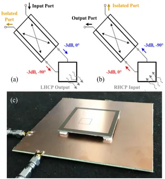
FIGURE 1. Four-element array (2 × 2) illustrating the relevant port numbering for dual circularly polarized (DCP) operation. (a): Schematic of the array and feed system. (b): Top aperture. (c): Antenna backside where the four hybrid couplers are visible. (d): Photograph of the antenna cross-section.
FIGURE 2. Schematic illustrating operation of the DCP single-element. (a): transmit mode left-handed circular polarization (LHCP). (b): receive mode left-handed circular polarization (RHCP). (c): photograph of a single-element prototype.
FIGURE 3. Layout of the aperture-coupled feeding system for the single-element within the proposed 2 × 2 array. Left: bottom view with the squared radiating patch transparency. Right: side view.
The key element of our proposed isolation approach in this paper consists of the integration of a hybrid feed system for the radiating patches in conjunction with additional slots enabling cancellation of the relevant currents, both at the patch aperture level and within the feed system itself. To the authors’ best knowledge, no similar antenna and array design, providing high-quality DCP features without the use of circulators, have been reported.
This offers significant cost savings and improved isolation with respect to conventional solutions and it has significant benefits for the examined Van Atta RDA application example, which does not require bi-directional amplifiers. Moreover,
the proposed 2 × 2 array (see Fig. 1) can enable automatic beam-steering; i.e., 2-D self-tracking in both the azimuth and elevation planes and with circular polarization (CP). Possible applications of this CP-RDA include new wireless power transmission (WPT) systems based on narrow band operation [4], such as for mobile phone charging, as well as for other 2-D beam steering systems for localization and tracking.
The DCP array may also be useful for monopulse radar, direction of arrival, and other localization systems when con-figured for sum and difference patterns. The added benefit of CP gives orientation flexibility and can avoid polarization mismatches. As discussed in the following, the results for the single elements and the array provide enhanced performances such as low SI between the input and output ports, a realized gain of more than 6 dBic, low axial ratios (ARs), and far-field beam steering off broadside.
II. SINGLE-ELEMENT: DESIGN AND OPERATION
The proposed two-port DCP planar antenna is constituted by two layers (see Figs. 2 and 3). The feeding structure is located on the bottom, which is made by a 1.6 mm thick FR4 substrate (εr = 4.3, tanδ = 0.02). In order to improve the radiation efficiency of the squared patch, the 1.52 mm thick upper layer is selected with a lower permittivity and loss tangent, i.e., a Taconic TLY-5A (εr=2.17, tanδ = 0.0015). The feeding structure is constituted by a printed double-box hybrid coupler, fed by two ports, i.e., P1 and P2 (as seen in Fig. 3, left panel). An input signal coming from one of the two ports is split into two equal, but 90-degree phase-shifted signals, thus each of them is coupled to an H-shaped aperture slot placed on a ground plane, as shown in Figs. 3 and 4. The structure is excited with the fundamental mode of the top patch producing linear polarized radiation. Therefore, the combination of the two transverse linear polarizations (one with a 90◦delay) allows for the generation of a CP beam. In particular, when P1 is used in transmitting mode as the input port, right-hand CP (RHCP) is achieved, while a left-hand CP (LHCP) signal can be acquired at the output port P2 (the opposite case is illustrated in Fig. 2).
On this basis, dual-polarized behavior can be obtained at each port by properly interchanging the role of P1 and P2. Note that the use of a printed double-box coupler, in place of a conventional 90-degree hybrid coupler, ensures better matching, improved Tx/Rx isolation, amplitude balance, and orthogonality of the quadrature signals, all features that are essential to provide a highly pure CP beam with a low axial ratio (AR). The H-shaped slot geometry and the λg/4stubs (with width and length Wlineand Lstub, respectively, as shown in Fig. 3, and whereλgis the guided wavelength, which is approximately equal toλ0/εr1/2) provide enhanced coupling to the top patch [14].
As it is known, the isolation between the two feeds of a double-port device can be significantly affected by the geometrical configuration of the radiating element [24].
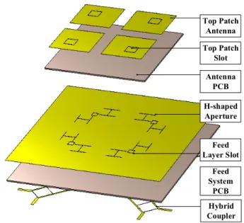
FIGURE 4. Stack up configuration of the complete structure: 2 × 2 square patch array, top slots, supporting antenna PCB, H-shaped aperture below the patches and in the antenna ground plane, feed layer slot, supporting feed system PCB, and the hybrid coupler.
As visible in Fig. 3, the considered H-shaped slot configura-tions are closely spaced, thus one can expect strong coupling for the surface currents circulating in the bottom layer both around and between the two apertures. Also, because of their size, the two H-shaped apertures are then very close to each other.
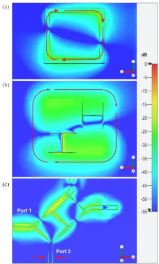
We just note that, since the slotline terminations can be considered short circuits [9], for the H-shaped apertures, the surface currents are very intense in these regions and can circulate from one aperture to the other, disturbing the port-to-port isolation and the AR performances for the antenna, as depicted by simulation results obtained with CST Microwave Studioin Fig. 5, where the electric field distribu-tion is reported on the various aperture planes of the antenna and the hybrid coupler, when no perturbing slots are present. By adopting isolation approaches as found in the litera-ture for linearly polarized antennas, port-to-port isolation can be improved. For example, the isolation of microstrip loop antennas has received some attention in the past, especially with regards to the design of MIMO antennas [10]. Following these developments, we implement here a new approach as illustrated in Figs. 2(c) and 4. A square slot loop for isolation is placed on the top radiating patch, so that it can be fed by means of slotline-to-slotline coupling from the two bottom H-shaped slots. The electric field distribution is shown in Fig. 6(a-b). Current flows from these feeding points (located in the middle of a loop side) through the isolation loop with a particular distribution. This implies that, when a current maximum is reached at one feeding point, a current minimum is reached at the other one. This helps to enhance the port-to-port isolation as well as preserve the required phase quadrature between the two H-shaped slots, thus gen-erating an AR improvement.
P. Le Bihan et al.: Dual-Polarized Aperture-Coupled Patch Antennas
FIGURE 5. Amplitude distribution of the electric field at the antenna operating frequency when no isolation slot loops are present. Different planes are shown: (a) top patch, (b) near the H-shaped slots, and (c), the bottom feed circuit.
FIGURE 6. Simulation of the electric field strength when an isolation loop is place on the top patch element only: (a) top patch view, and (b) bottom coupler. Simulations are also shown of the electric field considering the isolation slot loop positioned near the H-shaped slots: (c) H-shaped slot view and (d) the bottom coupler. As it can be observed for both cases, field values near the isolated ports are reduced when compared to Fig. 5 with no slot line loops.
A second and new approach can be defined by the addi-tion of a square slot loop directly on the ground plane, just between the two H-shaped slots. The simulated electric field
is shown in Figs. 6 (c) and (d). In this configuration, which to our knowledge has not been implemented previously, a por-tion of the surface currents are directly re-routed through the square loop, as represented in Fig. 6(c). The distance between the isolation loop and the terminations of the H-shaped slots needs to remain short and optimized to guarantee proper cou-pling for enhanced isolation and sustained antenna operation. III. SINGLE-ELEMENT PROTOTYPES
In order to experimentally assess the isolation performance, a few single-element prototypes have been fabricated and measured. One of these antennas is shown in Fig. 2(c). As briefly discussed above, the lower layer is made on a 125.5 × 125.5 mm FR4 square PCB, whereas a 54.4 × 54.4 mm upper Taconic square substrate is placed 3 mm above the bottom layer by foam spacers. Squared slotline loops having a side length of 9 mm were introduced on the top patch to maximize the isolation from 2.4 to 2.5 GHz. The relevant dimensions are summarized in Table 1.
TABLE 1.Slot loop on top patch: Prottotype dimensions (mm).
The simulated impedance matching in the absence of the slotline loops (not reported here for brevity), has provided satisfactory performance (well below −10 dB) and narrow-band isolation (5% for |S21| < −10 dB), with a maximum value of 25 dB at 2.45 GHz. This performance is, however, expected since the apertures generate orthogonal modes. The CP antenna operation provides AR values below 2.5 dB and a realized gain of 7.5 dBic. A comparison between the simulated and measured S-parameters for the antenna made with the loop on top (see Fig. 2(c)) is reported in Fig. 7(a), where a narrowband but strong isolation is achieved reaching 42.7 dB at 2.42 GHz. Broadband matching is observed as well.
The S-parameters of an alternative prototype are also reported, having the same dimensions except for the square loop (whose size is equal to 15 mm by 15 mm, contrasted with the 9 mm by 9 mm of the previous one), confirming the tuning capability of the maximum isolation frequency of the device. Simulation and measurements are only shown for Port P1 in Tx mode and Port P2 in Rx mode, P1 in Rx mode and P2 in Tx mode leading to the same results thanks to the symmetry of the structure. Figures 7(b) and (c) show that high CP purity is achieved with AR values below 2 dB at broadside, whereas Fig. 8(a) shows a gain value of more than 6 dBic and a half-power beamwidth (HPBW) of 60◦. The radiation efficiency is estimated using full-wave simulations and it is equal to 70% where losses are mainly related to the low-cost FR4 feeding circuit substrate.
A prototype including a slot loop on the ground plane has also been fabricated. The frequency of operation as well as
FIGURE 7. (a) S-parameters of the single-element antenna with a slot loop placed on the top radiating patch: 9 × 9 mm and the 15 × 15 mm square loop. (b) AR versus the zenith angle for the single-element at the isolation frequency for the 9 × 9 mm2slot loop placed on the top radiating patch. (c) Measured broadside AR versus frequency for the loop on the top patch and the ground plane.
FIGURE 8. Measurement of the realized far-field gain pattern in dBic (co-polarization) at the isolation frequency. (a) 9 × 9 mm2loop on the patch; (b) loop on the ground plane.
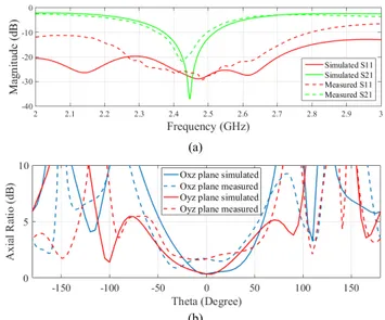
the dimensions are unchanged (see Table 2) except for Lslot2, which was optimized, and it is equal to 19 mm for this proto-type. The slotline loop is set to 9.6 mm. Even if the use of this additional element could be detrimental for the feeding cir-cuitry, this configuration still offers wideband matching, good antenna gain, narrowband but high isolation, and improved AR performance, as depicted in Figs. 8(b) and 9. In partic-ular, as seen in Fig. 8(b), the realized gain reaches 6.9 dBic with a HPBW equal to about 60◦. Differences between the simulations and the measurements should be attributed to the patch placement above the relevant feeding structure.
FIGURE 9. Single-element antenna with a slot loop placed on the ground plane. (a) Simulated versus measured S-parameters; (b) AR versus beam angle at the isolation frequency.
TABLE 2.Slot loop within ground plane: Prototype dimensions (mm).
As discussed, both the slotline configurations lead to strong but narrowband port-to-port isolation. To improve the band-width, we propose here another prototype constituted by a loop placed on the radiating patch and one on the ground plane, as depicted in Fig. 10(a). The two square slotline loops are implemented simultaneously and achieve improved isolation, as shown in Fig. 10(b), where a minimum value for |S21|of −54 dB is observed. This value is consistent with the
FIGURE 10. (a) Placement of the loops on the top radiating patch and the ground plane. (b) S-parameters when combining both loops (see Fig. 4).
P. Le Bihan et al.: Dual-Polarized Aperture-Coupled Patch Antennas
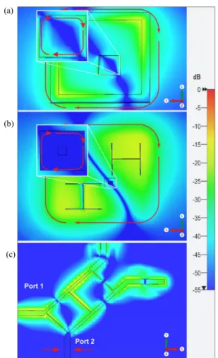
FIGURE 11. Amplitude distribution of electric field where the isolation slot loops are positioned on the top patch (a) as well as near the H-shaped slots (b) as in Fig. 4. Field values at the isolated port in (c) are well below the values as reported in Figs. 5 and 6.
port-to-port isolation as shown in the simulated electric field plots (see Fig. 11).
The matching properties are improved as well, achieving a very wideband behavior (|S11| < −20 dB from 2.1 GHz to 2.7 GHz as reported in Fig. 10(b)). The measured realized gain (not show here for brevity) reaches a maximum value of 8.28 dBic at broadside, which is in agreement with the sim-ulations. A measured HPBW equal to about 70◦in the princi-pal plane has been observed. Simulations and measurements also show good CP purity with AR values below 2.5 dB from −50◦to 50◦in the principal planes. We should mention that these measurements are performed, in this case, at 2.35 GHz, where the actual maximum isolation was observed.
We just note that the mentioned differences between the simulated and measured prototypes are likely due to several factors. For instance, the simulations do not take in account the insertion loss of the SMA connectors as well as the presence of the air foam spacers supporting the radiating patch. Furthermore, possible minor misplacements of the radiating patch above its feeding apertures, occurring during the manufacturing process, can likely lead to some perfor-mance degradation. All these practicalities in combination
with potential differences between the rated and the actual relative permittivity (because of the PCB manufacturing tol-erance), can impact the maximum isolation frequency. For example, a frequency shift can be observed between the sim-ulations and the measurements (from 2.4 GHz to 2.35 GHz, see Fig. 10(b)).
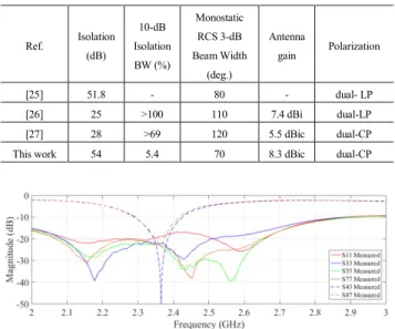
Table 3 compares the antenna performance with other sim-ilar DCP structures in the literature. To best knowledge of the authors, no similar antenna, and one with the reported values useful for full-duplex and DCP operation, have been reported previously. For example, by inspecting Table 3, it can be observed that the developed technique with parasitic loops on the top radiating patch as well as the ground plane provides superior DCP performance in terms of the measured isolation values, with isolation percentage bandwidths in excess of 5%. This may be suitable for radar applications requiring single-frequency beam steering as well as for WPT. Table 4, in addi-tion, reports a performance comparison with others antenna designs for RDA operation. It can be observed that our devel-oped prototype can provide improved isolation (significantly better with respect to refs. [26] and [27]) as well as improved gain whilst offering dual-CP operation.
TABLE 3.Measured performances summary (single-element).
IV. ARRAY DESIGN AND RESULTS
The single-element antenna designed and optimized in the previous section is considered here and optimized further for the demonstration of a 2 × 2 DCP array with application to a Van Atta RDA and sum/difference patterns. The isolation techniques, constituted by square slotlines on the top patches and on the ground plane, are employed (see Fig. 4). The prototyped array is shown in Fig. 1 where the four patch antennas are visible, each one fed by two highly isolated ports for DCP operation. The measured impedance matching is presented in Fig. 12, showing broadband performance and high isolation values (all results not shown for brevity due to the symmetry of the structure).
The proposed array can also be used to achieve con-ventional broadside radiation and beam steering. Simula-tions from CST Microwave Studio are reported in Fig. 13.
TABLE 4. Comparison of the proposed Van Atta RDA with other works.
FIGURE 12. Measured S-parameters of the array design (see Fig. 1). Reflection coefficient values are below −10 dB from 2 to 3 GHz. The interelement and adjacent element coupling values are below −50 dB and −20 dB, respectively, at the design frequency. Similar results are observed for the remaining ports.
FIGURE 13. (a) Beam steering within the xz-plane reporting the realized gain; (b) AR versus beam angle for different phasing configurations; (c) AR at broadside versus the frequency.
An RHCP beam at broadside, for instance, can be obtained by driving in quadrature ports 1, 3, 5, and 7 (see Fig. 1). To steer the direction of the main beam in the xz-plane, additional sequential phase delays equal to 40◦ are enforced between
ports 1, 3, 5 and 7. Fig. 13(a) also reports a 20-degree steered beam by applying a similar phasing but with a delay of 85◦. Beam steering off the principle/main planes is also possible and within both the xz- and yz-elevation planes and values of about 10 dBic are observed.
We just note that further increasing the scanning angle off broadside, one can observe high levels for the first side lobe, which is anyway below 10 dB from the main beam. Also, the small scanning angles do not significantly suffer from the intrinsic gain reduction typically observed when steering the beam towards endfire. We should also mention that the proposed array provides a HPBW of about 35◦, ensuring a pure CP beam with AR values below 3 dB both versus angle and frequency, as shown in Figs. 13(b) and (c). Measurements and simulations for the RHCP broadside radi-ation pattern (which are about 10 dBic) are also shown in Fig. 14 where a good agreement can be observed in terms of the pattern shape and the HPBW, which is about 40◦.
FIGURE 14. Measured and simulated beam patterns for the 2 × 2 array. Results are normalized considering a RHCP broadside beam in the two principal planes. Cross-polarization levels are less than 10 dB from the main co-polarized maximum defining an AR which is less than 3 dB at broadside.
A. VAN ATTA RETRODIRECTIVE ANTENNA ARRAY OPERATION
The proposed 2 × 2 array can be also employed as a DCP Van Atta RDA [2]. As is well known, this class of antenna circuit systems are self-phasing in which the incident wave incoming from a far-field source naturally induces a phase gradient at each element, and by phase conjugation, generates a back-reflection towards that same source. The achieved isolation at the ports is very useful for an RDA because when the elements within the array are connected in a crossed path orientation [2], as it is illustrated in Fig. 15(a), a new DCP Van Atta RDA can be realized for self-tracking in both the azimuth and elevation. It should also be mentioned that this RDA antenna system does not require a circulator and/or bi-directional amplifiers, which can be problematic and costly when considering more conventional RDA implementations. The simulated and measured back-reflected power versus
P. Le Bihan et al.: Dual-Polarized Aperture-Coupled Patch Antennas
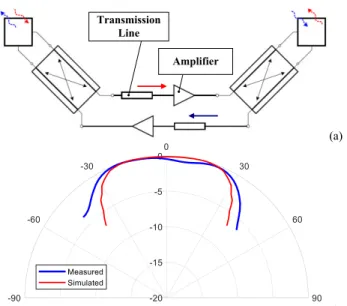
FIGURE 15. (a) Schematic illustrating the physical connections between an antenna pair defining an active Van Atta RDA. It should be mentioned that, for RDA operation, it is required that the total insertion phase difference between the incoming and outcoming signal paths (either red or blue paths) is maintained at 180◦defining phase conjugation. (b) Monostatic response of the proposed 2 × 2 array operating as an RDA system demonstrating self-tracking.
beam angle, when illuminating the array with a reference antenna, are reported in Fig. 15(b) at 2.35 GHz.
A good agreement for the simulations and measurements is observed in terms of the beam shape and the HPBW (which is about 70◦). During the measurements it should be mentioned that the single-element DCP antenna (using both isolation techniques with slot inclusions on the top patches and on the ground plane as reported in Section III) was used as the reference antenna, in both transmit and receive, while no amplifiers were employed in the array measurements for proof of concept defining a passive system demonstration. Also, to connect the antenna elements for the measurements, transmission lines were introduced to achieve a 180◦phase difference between each antenna pair, for proper Van Atta RDA operation.
If we compare the proposed Van Atta RDA with similar works (see Table 4), the achieved isolation is significantly improved as well as the gain; for example, values are well above 50 dB and 8 dBic, respectively. Moreover, the RDA is the only one that exhibits CP operation and with isolation values of 54 dB. This provides orientation flexibility of the transmit and receive antennas while maintaining full-duplex operation.
The response of the proposed 2 × 2 array is also a good candidate for mobile phone charging in the far field and narrowband WPT RDA applications based on high-power RF transmission [6]. In these cases, an incoming low-power beacon signal from a device to be charged is re-radiated back in the same direction (towards the beacon source) using an active RDA. As in [6], two separate transmit and receive antennas were employed for tracking in a single-plane only.
However, with the newly developed 2 × 2 dual-polarized array of this work (see Fig. 15), a single antenna unit can be employed for both transmission and reception with RDA tracking in both the azimuth and elevation planes. Further-more, the narrow band antenna response is needed in order to minimize any electromagnetic coupling effects from other radiating sources (acting like a filter) while maintaining CP antenna operation at a single frequency [6]. This is important since noise in the antenna system can introduce beam tracking errors of the retro-directed beam.
FIGURE 16. Measured and simulated sum and difference patterns.
B. SUM AND DIFFERENCE PATTERNS
Thanks to the double feed per each element of the array, the proposed 2 × 2 configuration can also be configured and measured for delta and sum patterns for monopulse appli-cations [20], [21]. The delta pattern, in particular, can be synthesized simultaneously exciting the odd or even ports. The sum pattern, instead, is achieved through the addition and sequential rotation of the signals at the ports, as mentioned previously. The far-field beams are shown in Fig. 16 where a good agreement can be observed between measurements and simulations.
V. CONCLUSION
In this work we have proposed and experimentally validated an original technique aiming to improve the isolation in dual circularly polarized aperture-coupled patch antennas. The novel approach makes use of parasitic square slotline loops placed on specific regions of the antenna patch and ground plane. Though narrow band, they provide high iso-lation values in excess of 50 dB, with good matching and polarization purity, outperforming similar devices proposed in the literature.
Different single-element antennas have been designed, simulated and measured, as well as a 2×2 array configuration providing the best performance and the most compact size. These cases have been validated through the manufacturing and measurement of various prototypes offering dual-circular polarization. Possible applications for the proposed RDA include far-field WPT, whereas the delta and sum patterns can be useful for monopulse and other localization applica-tions. Future work could also entail adapting the proposed structures for dual-linear polarization as well as approaches to improve the isolation bandwidth.
REFERENCES
[1] Z. Zhang, K. Long, A. V. Vasilakos, and L. Hanzo, ‘‘Full-duplex wireless communications: Challenges, solutions, and future research directions,’’
Proc. IEEE, vol. 104, no. 7, pp. 1369–1409, Feb. 2016.
[2] R. Y. Miyamoto and T. Itoh, ‘‘Retrodirective arrays for wireless communi-cations,’’ IEEE Microw. Mag., vol. 3, no. 1, pp. 71–79, Mar. 2002. [3] V. Fusco and N. Buchanan, ‘‘Developments in retrodirective array
technol-ogy,’’ IET Microw., Antennas Propag., vol. 7, no. 2, pp. 131–140, Jan. 2013. [4] P. Ang and G. V. Eleftheriades, ‘‘A passive redirecting Van Atta-type reflec-tor,’’ IEEE Antennas Wireless Propag. Lett., vol. 17, no. 4, pp. 689–692, Apr. 2018.
[5] W. Q. Wang, ‘‘Retrodirective frequency diverse array focusing for wireless information and power transfer,’’ IEEE J. Sel. Areas Commun., vol. 37, no. 1, pp. 61–73, Jan. 2019.
[6] P. D. H. Re, S. K. Podilchak, S. Rotenberg, G. Goussetis, and J. Lee, ‘‘Circularly polarized retrodirective antenna array for wireless power transmission,’’ IEEE Trans. Antennas Propag., to be published, doi:10.1109/TAP.2019.2952011.
[7] M. Ettorre, W. A. Alomar, and A. Grbic, ‘‘2-D Van Atta array of wideband, wideangle slots for radiative wireless power transfer sys-tems,’’ IEEE Trans. Antennas Propag., vol. 66, no. 9, pp. 4577–4585, Sep. 2018.
[8] J. R. James and P. S. Hall, Handbook of Microstrip Antennas (IEE Electro-magnetic Waves Series), vol. 28. London, U.K.: IEE, 1989.
[9] R. Garg, I. Bahl, and M. Bozzi, Microstrip Lines and Slotlines, 3rd ed. Norwood, MA, USA: Artech House, 2013.
[10] K. C. Lin and Y. C. Lin, ‘‘Isolation enhancement of dual-polarized slot-loop antennas for MIMO applications,’’ in Proc. IEEE Radio Wireless Symp., Jan. 2012, pp. 91–94.
[11] M. Berg, R. U. R. Lighari, T. Tuovinen, and E. T. Salonen, ‘‘Circularly polarized GPS antenna for simultaneous LHCP and RHCP reception with high isolation,’’ in Proc. Loughborough Antennas Propag. Conf., Nov. 2016, pp. 1–4.
[12] M. Mirmozafari, H. Saeidi-Manesh, and G. Zhang, ‘‘Highly isolated crossed dipole antenna with matched copolar beams,’’ Electron. Lett., vol. 54, no. 8, pp. 470–472, Mar. 2018.
[13] C. Zhang, X. Liang, X. Bai, J. Geng, and R. Jin, ‘‘A broadband dual circularly polarized patch antenna with wide beamwidth,’’ IEEE Antennas
Wireless Propag. Lett., vol. 13, pp. 1457–1460, 2014.
[14] D. M. Pozar, ‘‘A review of aperture coupled microstrip antennas: His-tory, operation, development, and applications,’’ Elect. Comput. Eng., Univ. Massachusetts Amherst, Amherst, MA, USA, Tech. Rep., pp. 1–9, May 1996.
[15] S. Karimkashi and Z. Guifu, ‘‘A dual-polarized series-fed microstrip antenna array with very high polarization purity for weather measure-ments,’’ IEEE Trans. Antennas Propag., vol. 61, no. 10, pp. 5315–5319, Oct. 2013.
[16] L. Zhong, J.-S. Hong, and H.-C. Zhou, ‘‘A dual-fed aperture-coupled microstrip antenna with polarization diversity,’’ IEEE Trans. Antennas
Propag., vol. 64, no. 10, pp. 4524–4529, Oct. 2016.
[17] E. Topak, J. Hasch, C. Wagner, and T. Zwick, ‘‘A novel millimeter-wave dual-fed phased array for beam steering,’’ IEEE Trans. Microw. Theory
Techn., vol. 61, no. 8, pp. 3140–3147, Aug. 2013.
[18] X.-Z. Lai, Z.-M. Xie, Q.-Q. Xie, and X.-L. Cen, ‘‘A dual circularly polarized RFID reader antenna with wideband isolation,’’ IEEE Antennas
Wireless Propag. Lett., vol. 12, pp. 1630–1633, 2013.
[19] P. Le Bihan, Y. Zhaksylyk, P. D. H. Re, S. K. Podilchak, M. García-Vigueras, and G. Goussetis, ‘‘Dual-circularly polarized patch antenna using simple isolation techniques and its array application,’’ in Proc. 12th Eur. Conf. Antennas Propag., 2018, pp. 776–785. [20] S. G. Kim and K. Chang, ‘‘Low-cost monopulse antenna using
bi-directionally-fed microstrip patch array,’’ Electron. Lett., vol. 39, no. 20, pp. 1428–1429, Oct. 2003.
[21] H. Wang, D. G. Fang, and X. G. Chen, ‘‘A compact single layer monopulse microstrip antenna array,’’ IEEE Trans. Antennas Propag., vol. 54, no. 2, pp. 503–509, Feb. 2006.
[22] D. Comite, S. K. Podilchak, P. Baccarelli, P. Burghignoli, A. Galli, A. P. Freundorfer, and Y. M. M. Antar, ‘‘Design of a polarization-diverse planar leaky-wave antenna for broadside radiation,’’ IEEE Access, vol. 7, pp. 28672–28683, 2019.
[23] A. Vosoogh, A. Haddadi, A. U. Zaman, J. Yang, H. Zirath, and A. A. Kishk, ‘‘W-band low-profile monopulse slot array antenna based on gap waveg-uide corporate-feed network,’’ IEEE Trans. Antennas Propag., vol. 66, no. 12, pp. 6997–7009, Dec. 2018.
[24] G. Kumar and K. P. Ray, Broadband Microstrip Antennas. Norwood, MA, USA: Artech House, 2003, pp. 55–58.
[25] M. G. Christodoulou and D. P. Chrissoulidis, ‘‘2D Van Atta retrodirective array using dual polarized two-port square microstrip patches,’’ in Proc.
11th Int. Conf. Antennas Propag., vol. 2, Apr. 2001, pp. 814–816. [26] H. I. El-Sawaf, A. M. El-Tager, and A. M. Ghuneim, ‘‘A proposed
2-D active Van Atta retrodirective array using dual-polarized microstrip antenna,’’ in Proc. Asia Pacific Microw. Conf., 2012, pp. 1103–1105. [27] K. W. Wong, L. Chiu, and Q. Xue, ‘‘A 2-D Van Atta array using
star-shaped antenna elements,’’ IEEE Trans. Antennas Propag., vol. 55, no. 4, pp. 1204–1206, Apr. 2007.