HAL Id: hal-00422169
https://hal.archives-ouvertes.fr/hal-00422169
Submitted on 6 Oct 2009HAL is a multi-disciplinary open access archive for the deposit and dissemination of sci-entific research documents, whether they are pub-lished or not. The documents may come from teaching and research institutions in France or abroad, or from public or private research centers.
L’archive ouverte pluridisciplinaire HAL, est destinée au dépôt et à la diffusion de documents scientifiques de niveau recherche, publiés ou non, émanant des établissements d’enseignement et de recherche français ou étrangers, des laboratoires publics ou privés.
New trends in Reverse-Engineering:
Augmented-Semantic models for redesign of existing
objects
Alain Bernard, Florent Laroche, Sébastien Remy, Alexandre Durupt
To cite this version:
Alain Bernard, Florent Laroche, Sébastien Remy, Alexandre Durupt. New trends in Engineering: Augmented-Semantic models for redesign of existing objects. Ouvrage collectif Reverse-Engineering, 2010, 27 p. �hal-00422169�
New trends in RE: Augmented-Semantic
models for redesign of existing objects
A. BERNARD(1), A. DURUPT(2), F. LAROCHE(1), S. REMY(2)
(1) IRCCyN – Ecole Centrale de Nantes, 1, rue de la Noë, BP 92101, 44321 –
NANTES Cedex 3 ; tel: + 33 2 40 37 68 08 ; email:
[email protected], [email protected]
(2) Université de Technologie de Troyes, 12 Rue Marie Curie - BP 2060 -
10010 Troyes ; Tel +33 3 25 71 85 56 ; email: [email protected],
[email protected]
I. INTRODUCTION
Reverse engineering is an approach that is used in many domains like electrical engineering, computer sciences and many others. The main object of RE is the analysis of an existing product (that can be a software application, a mechanical product …) in order to produce a copy and/or an improved release of this one.
In this chapter, we focus on reverse engineering in the mechanical engineering domain. According to that domain, the subject is a physical part. It could be a hand-made prototype, an old mechanical part, a modified part or tool, and, sometimes, a product of a competitor. It means that reverse engineering is used by people during any stage of the product development process. Actually, the needs of these different actors are very different but the fact is that current reverse engineering methodologies often propose only one type of approaches.
Today, reverse engineering methodologies propose mainly geometric approach. This one generally considers a 3D point cloud from a 3D digitisation and enables an expert to fit a meshed surface or free form surfaces on this point cloud. The resulting model is a geometric shell that can be used efficiently by some of the actors of the product development process. For example, a meshed model can be used for mechanical analysis purpose. As a matter of fact, in many other cases, such a geometric model is not enough and knowledge about the history of the product is needed in order to improve the virtual model rebuilding.
Late commercial solutions such as GeomagicTM or RapidFormTM, for example or complete CAD application software such as CATIATM are very efficient as they add segmentation algorithms, sketchers and/or many other facilities to the original surface rebuilding tools. These kinds of applications enable to rebuild the geometry of the object as a set of functions (protrusion, revolution, sweep…), they enable to add colours and textures, they enable realistic kinematical animation and many other things...
Because the geometry of a given product is the consequence of an important process, it is important to try to recover any evidence of its past life (including socio-economical aspects, the design intents of the former designer, its different uses…) from its geometry in order to produce a model of a good quality. Such a model can provide important possibilities of Reverse Engineering. It enables to restudy the product more efficiently than a geometrical model based on a mesh or on free form surfaces.
This chapter proposes approaches and methodologies that illustrate the recovering of these evidences and the use of this knowledge as explained by figure 1. There are two parts in this chapter. The first one proposes the general approach. It deals with how to integrate knowledge about mechanical product. Knowledge about the historical and economical environments of the product has to be considered as well as functional aspect in order to obtain a useful digital mock up that enable to redesign these products. The second part of the chapter focuses on a particular aspect of this general approach. It deals with manufacturing and functional knowledge about the product in order to improve the rebuilt CAD model of this product. An original CAD model is feature based and these features are the consequence of this knowledge.
Figure 1. Reverse Engineering for X: the object and its context.
II. IMPROVING REVERSE ENGINEERING OPERATION BY
INTEGRATING KNOWLEDGE ABOUT THE PRODUCT
In this part, we present a new way of thinking object 3d digitalisation and Reverse Engineering. Our approach deals with a mix of two scientific communities: mechanical engineering and technical history. Indeed, when we speak about technical history, it reminds us old industries and old machines.
Nowadays, protection of our technical heritage reveals questions about methods, tools and competences that have to be used for capitalising and valorising it. In fact, for 200 years, objects have become more and more complex; consequently, new methods and new tools have to be defined for this museology of the 3rd millennium. In order to resolve the problem of object conservation, one possibility consists of virtualising old objects; indeed, it is a new application for 3D digitalisation and Reverse Engineering. Obviously, the first basic tools use for physical capture are decametres, slide callipers, micrometer callipers. However, in order to optimize cost and time, for measuring complex machines, 3D digitalisation can be employed: TMM laser radar, X-ray, 3D scanner laser with topographical reconstruction in real-time …
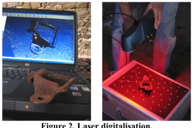
Moreover, as we usually work with old objects, contact can be sometimes impossible or even forbidden. The best solution for 3D digitalisation has to be identified clearly and the choice must consider external constraints from environmental surroundings (figure 2).
This Figure 2 presents, on the left, the part and the screen of the computer showing the mesh built during the scanning phase, on the right, the digitizing process with a Handyscan sensor in use.
Concerning application domains, we can for example consider the availability of the technical drawings done by Leonard de Vinci: could the machine really work? In this way, researchers of the Museum of Florence in Italy have designed virtually the automobile imagined by de Vinci in order to understand how it works. Then, they have built a prototype to validate the CAD model. [Fiorenzoli 2004].
Our main hypothesis is to consider the environment of the object before digitalising it: this includes questions about its lifecycle, about human beings that used it… A technical object is not only a dead artefact; it is something that reveals records, knowledge and know-how. Studying both social and technical environment of an object can enable a better understanding of it and obviously a better 3D digitalisation and reconstruction process.
As an example, considering the museological point of view, the social aspect is very important. Researches have to be done in order to improve the point of view of visitors. As described in Paul Rasse’s [Rasse 1991]: "Nowadays, in museums, we are very far from the factory and the workshop, the noise and dust, tiredness and sweat, […] the violence of the social relationships contribute to the history of technologies".
Today, the situation of technical and industrial heritage raises many problems: How can we manage and develop it considering a given context that can be reverse engineering for museum or reverse engineering for maintenance for example? How can we ensure life prolongation for the technical information of the collections, archives and heritage sites? This technical information, testimony of the past, is ageing very quickly; like a puzzle where parts wear or disappear, the technical data disappear progressively with the time.
Conservation of technical heritage encounters several major difficulties coming mainly from:
a poor sensitisation of the industrial world regarding the value of their technical heritage and their interest in the possibilities of heritage backup;
financial difficulties to conserve, maintain and ensure the transportation of large size objects;
a human difficulty due to the lack and the loss of the user consciousness and/or the disappearance of the machine designers and manufacturers.
Understanding an old technical machine can be easy to achieve for former workers but it can be difficult and highly delicate for people who make the reverse engineering.
Consequently, a new question appears: what can be done with the industrial knowledge? Could methods and tools used in industrial and mechanical engineering provide an answer to this new need: from knowledge extraction and capitalisation to the object 3D digitalisation going though the rebuilding of the CAD model, the dynamic mock up to a virtual show? It is a new reverse-engineering process we propose to transpose from Mechanical and Industrial Engineering to what we can call Reverse Engineering for X (Reverse Engineering for Advanced Industrial Archaeology or Reverse Engineering for Manufacturing for example).
2.1. Improving digitalisation process
Saving and maintaining physical objects can be very costly and sometimes nearly impossible as the machine crumbles to dust. However, we have to rebuild it as a numerical object. Consequently, engineers and industrial engineering tools and methods can give answers for the capitalisation, conservation, popularisation, redesign, maintenance, remanufacture … of old machines.
Our proposition consists in reversing the design time axis from end of lifetime back to the initial need. Thanks to a re-design by modelling of the technical machines and a contextualisation in its environment, it can be possible to restore it for multiple finalities and more widely to restore the working situation of the socio-technical production system [Bernard & al 2002] or the design intents [Durupt et al 2008].
Let’s take the example of RE for Advanced Industrial Archaeology. Old machines do not operate or cannot be exhibited in a museum. New technologies could be a real and realistic new solution for capitalising the heritage. Globally, there is always the problem of cost and security to preserve the machine functionalities: components wear, the need of a machine driver etc. Virtual Reality is a new mediation tool. Contrary to videos and thanks to interactivity, it is easier to understand the operating situation: the visitor is no longer a spectator but an actor. As he is immersed in the system, he can test the virtual machine to its limits. Moreover, the mediation-tool detail level can be adapted by the curators to the targeted public and thus make the machines become alive.
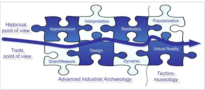
Figure 3 details the global overview process proposed. It demonstrates the interoperability possibilities between social sciences and engineer sciences. Two main steps can be deployed:
1. Advanced Industrial Archaeology object and knowledge capture, 2. Techno-museology popularization of the knowledge.
Figure 3. Global process methodology
The need is defined by the action chain resulting from technical history:
Apprehension is defined by the action of understanding, of grasping by perception, imagination, memory... Interpretation is defined by the action of giving an explanation or a meaning. Restitution is the fact of giving back something. Popularisation consists in emphasizing. Popularisation is a subclass of popularisation: when popularizing, we allow everybody to have access to the object and its associated knowledge.
Tools and methods are defined by the digital chain from industrial engineering:
Information Capture (physical and textual) 3D design dynamic simulations (mechanical
and Situations of use) Virtual Reality applications
Later in this chapter, we will present other examples as we will focus on the extraction and formalisation of manufacturing and design knowledge.
2.2. Definition of an object and its context
Before capitalising knowledge (material or immaterial), it is necessary to identify it. In this part, we will define what we call the material knowledge characterized by the real object and immaterial knowledge associated to it. As per terms of the APTE method related to the external functional analysis, this external knowledge can be defined as: the external environment of the object in its common use context.
From an only geometrical point of view, an object is a finite element which is fixed and limited [Jeantet 1998]. Within an epistemological framework, the object is defined as an artefact. According to the biologist Jacques Monod: "Any artefact is the product of a human being who expresses in a real obvious way one of the fundamental properties characterising all the human beings: they are part of a project and they are representing within their structures and their performance achievement (for example, the creation of artefacts)." [Monod 1970]
Human industry can also be qualified as a production. The created artefact or the created object is qualified and quantified. It is part of the real world and presents a physical structure and a function (often associated with the performance concept). The object can be designed either from the structure towards the function or from the function towards the structure (FBS-PPRE model from Michel Labrousse [Labrousse 2004]).
Reverse Engineering of technical machines also means to capitalise its operating mechanism by taking into account its technical and social context. Mechanically, operating is defined by functions and associated kinematics but also by processes and situations of use. Consequently, an object is considered as a technical and industrial one if it can be set in a socio-technical system. According to an epistemological point of view of the technical historian, an object must be contextualized so as to determine its value and to understand how it operates.
Usually, knowledge capitalisation only concerns the design and the manufacturing industries (We will focus on this domain later on this chapter); centred on the product itself, the extracted knowledge gives jobs laws, best practices… Rarely other internal knowledge of the enterprise is added: cost… Moreover external knowledge from the enterprise is also nearly ever capitalised. Indeed, according to an historian point of view: it misses the context of the capitalization.
The analysis of an industrial context according to an historian point of view allows determining three levels of details: first the machine, secondly the workshop, then the factory. It is what we call the Russian dolls concept (see figure 4).
Figure 4. The Russian dolls concept.
A machine is designed, built and used for a known goal; it is settled in a shop floor and put in correlation with other shop floors in the factory. Studying this setting up and the links between machines and humans can lead to a global situation model. In correlation with the previous enumeration, it presents three corresponding contexts :
Zoom level definition What kind of context?
Machine + Human Technological Shop floor Organizational Manufactory Social
2.3. The concept of extended time
If we analyse design methods used by enterprises (APTE, AMDEC, QFD, 6 Sigma…), few of them take into account the time concept. However, time plays an important role at any scale of a process:
- product time: it is the formalization of the Product Life-Cycle (PLC) that allows every actors of a development project to integrate all the other domains into its design part: how the idea was born in the R&D platform? How the object will be used by the client?...
- industrial environment time: it can be divided into two parts: the work time and the process time. However, both are currently fitted together. This time describes the interactions between the product and the machines or between the product and the humans who produce or use the artefact.
This time concept used in an industrial way relates only to a short period. If one first step of knowledge management is unrolled during a life part of a product and one other step few years later, usually, there is no link between both capitalizations.
However, most of the time, it has been demonstrated that a product will probably have many life’s or many use situations. Many examples can be detailed for illustrating this theory. Let’s take the example of a “pen”.
A pen is designed and manufactured by one first enterprise. Secondly, the pen is distributed by a supermarket and sold to the future user. This user can lose his pen at work and one of his collaborators will find it and use it again until the pen will no longer work; consequently, it will be discarded out to the bin or recycled.
In this example, the evolution time considered is the product time or the human time as the action occurred during a definite time that can be measured at a human scale. Let’s give now an example with a time period evolution much longer: over 140 years.
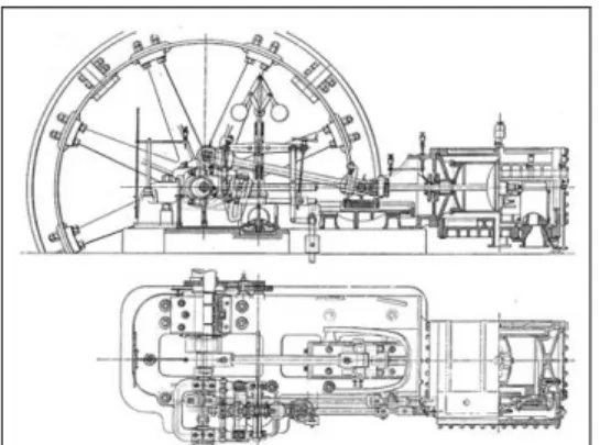
It is the story of a steam engine that has been designed by Alphonse Duvergier in 1860 (Alphonse Duvergier is born in 1818 and died in 1879). This steam engine has worked so well in the industries that in 1890, nearly 600 machines have been built and sent all over the world. In 1898, four specimens of this steam engine are built by Piguet enterprise (Duvergier successors) and installed in Monte-Carlo; coupled to a dynamo, they produce electricity for lighting the Prince Palace and the Casino (figure 5). But, in 1917, due to a bad management, the company decide to change the technology; one of the machine is sent in a sawmill near Moulins in France. In 1930, the machine is bought by another sawmill near Dijon in France (figure 8). It has worked in this factory for producing electricity until 1977; at this period, producing energy inside its own enterprise is more expensive than buying electricity to the French national company. Consequently, the steam engine is stopped and in 1994, the steam engine is dismantled by the Ecomusée du Creusot-Monceau in France in order to be stored in its reserve. [Laroche 2007]
Unused for 12 years, the machine is still stored; it has not been restored and it can not work any more.
Figure 5. 1886: Steam engine from Piguet catalogue.
In this example, the evolution time considered can not be a human time as nearly 3 generations have seen the steam engine in evolution. Consequently, it is necessary to extend the time axis; we call it the “earth time”.
Moreover, according to those two examples, we can see that the object can reach many “Use life”. If the terminology “use life” is used from the object birth to its death, dynamic situations are:
- research and design, - manufacturing, - sale,
- use life 1, - …
- use life n,
- end-of-life (heritage / recycling / dismantling).
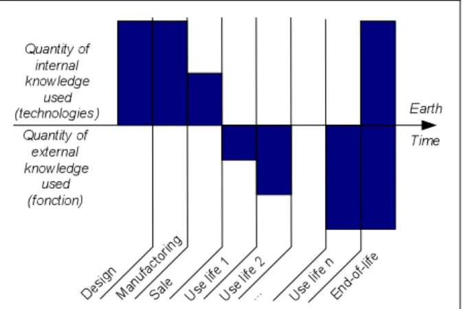
During the object life, amount of knowledge is accumulated. It can be classified into two parts:
- internal knowledge used: we speak here in terms of technologies as defined by the Functional Bloc Diagram,
- external knowledge used: here, only the function is taken into account as the object is used for its primary function.
Let’s put in correlation the amount of knowledge generated and the extended PLC according to an “earth time”, it can be summed up by figure 7.
Figure 7. The extended PLC and associated knowledge. 2.4. Context and Life Cyle
Historian approaches propose to take into account the global time concept of the product evolution in function of the human evolution: it is the "technological context". Global time is different from earth time as global time can be expanded or reduced; it is not a uniformed time and not at a constant scale as it takes into account the human evolution.
But usually technological analysis is not enough; the environment of the machine also has to be considered: this is the organisational context. The studies concentrate on the flows created or used by the machine. Using industrial terms, we can speak about fluid flows, product flows, manufacturing constraints … and interactions between the machine and the other machines of the factory or interactions between the machine and the employees: that's
why we call it the organisational context. Nowadays, knowledge management concentrates on PLC and know-how. What about the enterprise organisation, the project organisation? What about capitalisation methods? Before focusing on the product, it is the management setting up that really allowed the success of a product. Some difficulties appear here: capitalising something considering the evolution is a new way of thinking for engineering sciences. However, according to what is said in the previous part of this chapter, the proposed approach can improve the understanding of enterprise works and perhaps help to prepare future enterprise generations.
Moreover, historians give an important place to human beings. Obviously, everything built and used by human beings is made for improving their standards of living. Defining the evolution of the couple human beings/technologies (here technologies mean all the artefacts surrounding human beings), the social context plays a role in the human evolution.
In his book "the life of objects", the anthropologist Thierry Bonnot states that "an object takes a meaning only in a human context" [Bonnot 2002]. A machine or a system is significant only if it can relate to a social act and if it can help to conserve all the aspects of a technical culture, i.e. the physical objects but also the vestiges it contains: gestures, know-how, social relations etc. The object studied cannot be dissociated from its context (know-how, political context, social context, economic context etc.). Just like the photocopy gives back the object within its framework, the sound track on which has been recorded critical information for a better understanding of the object, or the written report where the human context has been consigned, all those elements enable the re-contextualisation of the object [Rolland 2001]). Consequently, depending on the desired finalities of the popularization, it will be advisable to capitalize all the necessary knowledge for achieving this goal.
Indeed, understanding and studying an old technical object requires large contextualization. Consequently, we will have to consider many various sources [Laroche & al 2006]. Here are some examples of sources:
machine drawings published by manufacturers;
plant layout, cartography of the factory, physical mock-up; catalogues, patents, general documents of the manufacturer; handbooks, specialized reviews, World Fair reports;
private industrial files or public funds (J series of the French departmental records); technical and industrial public files (M and S series of the French departmental
records, public records);
interviews, anthropological and sociological investigations; …
Sometimes, the physical object is in such an advanced state of deterioration that digitalization would be without interest or impossible as the object no longer exists in the industrial plant. That is why, if additional capitalized knowledge is sufficient, it will be possible to carry out an extrapolated virtual reconstitution, that will be more authentic.
2.5. Advanced Industrial Archaeology as an example of application
In this part we describe what we call Advanced Industrial Archaeology. We will focus on the first step of the process: the reverse-engineering phase. Figure 8 details the main steps that must be followed for virtualising a physical object and associated knowledge.
Figure 8. Reverse-engineering methodology
According to figure 8, to create a digital model of an old technical object, several phases are required. The process consists in digitizing the object in order to immortalize it and to produce data that will be coherent, readable and transmissible to future generations.
However, many questions must be answered. Among them, before designing a virtual model, it is necessary to identify and capitalise the required information. Both internal and external knowledge have to be extracted as explained before. However, notice that the source of information, which is the most important, is obviously the object itself if it still exists. Consequently, picking up information on the object or its components gives more authenticity than extrapolating a drawing or a cloud of points.
Methodology associated to figure 8 is:
1. an object skeleton has to be designed;
2. adding the concept of time, it will produce a kinematic sketch; drawn in 3D space, it will produce a wireframe that has to move back-and-forth with the physical object in order to validate it and to fix the dynamic;
3. the last step will produce new knowledge maturation: the mechanism understanding; 4. next the dynamic digital model is created by anchoring solids on the skeleton.
Determining the state of the object
At the beginning of the study, the object life period that has to be represented in the digitalization process and the modelling process must be determined and detailed:
"new" object, in its initial state of first use;
object in use with possibilities of including adaptations and innovations; object at the end of lifetime;
object in its archaeological state of discovery or when it was decided to preserve it; object partially extrapolated.
Digitalization
If the object exists partially or entirely at the time of the study, it is possible to digitize it directly in three dimensions in order to collect its geometry. Several solutions of digitalization exist: laser scanning, photogrammetry, measurement systems with contacts etc. According to
the size of the object, its material nature and its state of deterioration, the technologies used may be different. In the next part of this paper, we will develop the digitalization methodology we have set up.
It should be noted that if the object no longer exists, it will be possible to design an extrapolated model thanks to external documents and knowledge, (see paragraph before).
Re-designing: static components
The digitalized dots obtained have to be treated in order to be able to design the various components of the object. Taking into account the file size and the wish to create a realistic model, we would prefer solid design instead of surfacing.
Moreover, as modelling is costly in terms of time and money, it is necessary to specify the model accuracy level expected: screws, chamfers, precision for moulding parts etc It is the same problem as has been encountered with over-quality in manufacturing processes.
Re-designing: dynamic functions
As used objects are not inert, they are animated by mechanisms that have to be virtually restored and simulated in order to validate operating [Van Houten & al 2000]. In the first step of our heritage process, it is essential to produce a functional virtual model that is mechanically realistic and as accurate as possible. That is why using CAD programs is better than using CG (Computer Graphics) programmes. CG programmes are usually used for creating animated pictures, movies etc. With CG programmes, simulations and dynamics are not realistic as a "world" is created in which one the objects will move but this world does not have the properties of the terrestrial physical laws such as the fundamental principles of mechanics (examples: gravity, stress, speed, acceleration). The digital mock-up will be realistic and not real; but as realistic as it can be [Eversheim & al 2000]. Obviously, digital files will never replace physical objects: there is only one way to represent reality [Laroche & al 2005].
Environment and other dynamic flows
Except for kinematics, simulations are carried out in post-processing and without direct visualization. For example, this is a problem for modelling fluids: in the case of a steam engine, it is actually very difficult to visualize the steam exchanges inside CAD software. However, such visualization is essential for curators and all non-expert people.
It will also be necessary to consider the need of environmental restitution of the machine: actuators and motors, the nearest machines, the industrial plant, etc. Do they have to be digitized and modelled?
Materials and other aspects
An object is defined by its geometrical characteristics ("3D") and its kinematic functional properties ("3D+t"). But functionalities could also be due to the material properties used: it is necessary to carry out a virtualisation of materials.
In the same way, materials or paintings are design information that could be essential for a future restitution and that must be taken into account during the digitalization step.
Where are the limits of the external appearances in relation to the concept of authenticity? Is it necessary to restore false colours to prove virtuality?
With regard to design, an object can be characterized by its colorimetric but also by auditive and olfactive perceptions: how to capitalize on sounds and odours in digital form?
Notice that this information has sometimes disappeared with the dismantling or the non-possibility of operating the machine.
2.6. Involving inter-disciplinary teams
All what have been explained before show us that for achieving those kinds of projects, it requires multiples know-how. Consequently, the project team must have multiples competencies. If the context of the object has also to be capitalised, having people aware of 3D digitisation and reconstruction is not enough. In order to rich a better result, the project team must be interdisciplinary. But let’s first compare to nowadays…
To create and design new products, new competences are required. Consequently: • multidisciplinary teams are constituted allowing to work with various competences; • collaboration tools are created for simplifying engineering process.
However, otherwise there is a multiplicity of the competences involved; all team members belong to a similar/same domain: design and/or engineering. Either they are designers, ergonomics or engineers, ideas and knowledge manipulated reach to a common semantic. It is the reference model of collaboration.
Researches we developed upon heritage reverse-engineering of ancient machines also require numerous competences. But, our team combines knowledge domains that generally do not work together. Then, there are some problems of communication and interpretation.
Main difficulties come from the language barrier between past and present. Indeed, old documents use old technical vocabulary which is difficult to understand for engineers of the 21st century. Therefore, historians must help them to translate and interpret technology's descriptions; they succeed it by taking into account the context of the object.
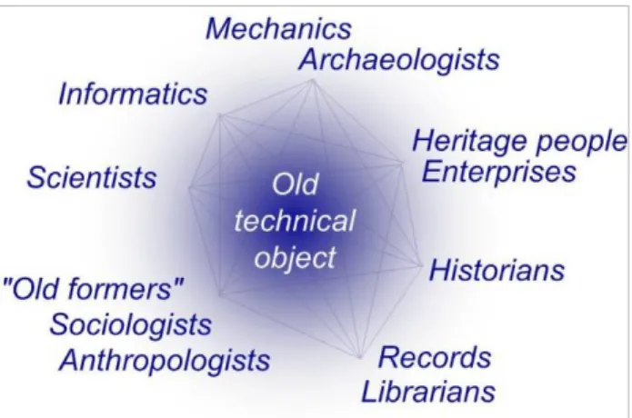
Experiences we have done need inter-disciplinary teams compound of jobs represented by figure 9. It is a new kind a cooperation process as some competences required jobs that do not exist yet; moreover, notice that most of the time there are no appellations for describing them. For example, we can imagine a new training for creating engineers-historians devoted to the understanding of product origins and their links with technologies: it will be the Industrial Archaeologist.
Figure 9. The collaboration network for creating an interdisciplinary team in a reverse-engineering process
Each competence will work at a given step of the heritage reverse-engineering process for capitalizing and formalizing knowledge involved. However, tasks will be done in parallel and not discontinuously. For example: output data of job n° 1 is necessary for input data of job n°2 but same job n°2 is going to produce new knowledge which job n°1 is going to reuse; back-and-forth is perpetual and synchronized between all competences.
Generally, we can distinguish:
• The technologist who is a specialist of scientific domains involved. He helps to understand the basic principles of the machine operating.
• The technologist with a mechanical background. He analyzes the object and is able to design a 3D model in order to simulate and validate the dynamic situations. Mechanical man also ensures the industrial archaeology phase on plant.
• The technologist who is an expert in computer science. He creates the knowledge data base and resolves interoperability problems from the 3D digitalization to the implementation in a virtual reality application.
• Persons that hold the know-how; most of the time they are ancient former of the company. They can be accompanied during their work by sociologists or anthropologists that will be able to adapt their speech to contemporary language.
• Persons that work in heritage domain; they are traditionally the sleeping partners. They have established special relationship with the enterprise in which the machine stays; consequently, they allow the inter-disciplinary team to access to numerous private records (when existing).
• Librarians and archivists. For example, they can found international standards or patent offices; those documents are indispensable for a better understanding of the technologies. • The historians who are specialized of the domains involved. They do an interface between
scientists, technologists and persons that hold the knowledge and/or the know-how. Historians also assume the role of translator for making ancient documents comprehensible by contemporary specialists. Moreover, they have a global overview of the object life evolution (they are the technological geneticists).
In the following sections of this chapter, we focus on a particular aspect of the reverse engineering domain. It deals with manufacturing and functional knowledge about the product in order to improve the rebuilt CAD model of this product. An original CAD model is feature based and these features are the consequence of this knowledge.
In the following sections of this chapter, we focus on a particular aspect of the reverse engineering domain. It deals with manufacturing and functional knowledge about the product in order to improve the rebuilt CAD model of this product. An original CAD model is feature based and these features are the consequence of this knowledge.
III. FOCUS ON REVERSE ENGINEERING FOR X IN MECHANICAL
AND INDUSTRIAL ENGINEERING
Today, companies, organisation and suppliers need to manufacture old parts or products they use everyday. Generally, R.E consists in taking a point cloud from the original surfaces of the object using 3D digitising facilities. The point cloud can be performed using software applications for surfaces reconstruction. Issued model can be used for calculus, rapid prototyping and/or process planning. After processing, CAD model could be modified. In fact, geometry must be adjusted, thus, the object have to be redesigned. In the scientific
literature, reverse engineering is to convert a large point cloud into accurate, fair and consistent CAD model [Benko et al , 2004]. Current algorithms or software applications are designed in order to obtain an accurate CAD model. Hence, regarding the current approaches and according to users, the results obtained are not good enough because geometrical models rebuilt are generally frozen or static. As presented in the introduction of this chapter, consistent CAD model can be rebuilt using late commercial software applications. In this case, it is possible to obtain a model that enables re-design approach but it is a very long set of geometric operations.
This section suggests that it is possible to consider manufacturing and functional knowledge about the product in order to improve the rebuilt CAD model of this product. In fact, into real CAD model, designers put data about expert knowledge (with parameters and relationships), the manufacturing process, the function of the product, etc…
This knowledge reveals relationships, constraints and parameters between each geometrical feature within the object. Thus, this knowledge could allow improving the CAD model reconstruction process.
This section proposes a new methodology that considers knowledge about some aspects of the lifecycle of the original product. A geometrical approach is not enough for obtaining a real CAD model. The knowledge dealing with the product, its lifecycle and its environment have to be considered as well as the geometric appearance. We propose to describe how to formalise this knowledge and to semi-automate the rebuilding methodology. We call this approach “Reverse Engineering for X”. Objectives are to obtain a real CAD model with a tree structure of features called functional and structural skeleton. The originality of the proposed approach is the merging between a classical geometrical approach (point cloud segmentation and features data extraction) and the knowledge based approach proposed in this chapter.
In the first part of this section, we propose a classification of segmentation processes and the different methodologies that enable to reveal knowledge about a given product.
The second part presents “Reverse Engineering for X” concept through several use cases.
3.1. Review of Related Work
3.1.1 Segmentation techniques
Segmentation is a complex iterative process that aims to logically divide the original point cloud into a set of point clouds, one for each feature, such that it contains just those points sampled from this particular feature. There are diverse methods for segmentation, which differ according to the measurement quality, the number of points, the geometric characteristics of the product and the amount of human interactions required.
The 2D types of segmentation techniques deals with 2D images but can be applied to 2D1/2 point clouds. They are Range Image Segmentation and Range Data Segmentation [Besl et al. 1988], [Yokoya et al 1989], [Sapidis et al. 1995].
The 3D segmentation of a 3-D digitized data (Point Cloud) is more interesting in the research context. These types of point clouds are obtained using 3D sensors. These sensors
can be from several types (structured light, laser triangulation, contact …) and are often integrated on several devices (Coordinate Measuring Machine, 3D measurement arm …). These point clouds are sets of unorganised points representing 3D objects. We purpose an overview of several segmentation techniques. [Patané et al 2002] proposed an approach for Edge-based segmentation and extraction of feature lines based on a multi-resolution representation and analysis of the scan data. In this approach, based on a sequence of local updates, the point cloud is organized according to a multi-resolution hierarchy. The application domain of this approach is defined by scan lines. This approach is characterized by three phases; a) Multi-resolution data modelling, b) A scale and a geometry classification based on form feature similarity, and c) A two step line by line detection phase and segmentation. [Woo et al. 2002] introduced a different Edge-based segmentation approach that uses an Octree-based 3-D grid splitting process. An iterative subdivision of cells is done based on the normal values of points, and the region growing process to merge the divided cells into several groups. A triangulation method is used in estimating the normal point. The input for this algorithm is a well organized point cloud based on the scan line from a strip type laser scanner. [Benko et al. 2001] used a non-iterative approach “Direct Segmentation” based on the fact that it is possible to compute local characteristic quantities (e.g. normal direction) within the interior face. This characterizes the planarity of the point neighbourhood. Then, a second order algebraic surface is fitted to surrounding points in the neighbourhood. However, direct segmentation produces disjoint regions, each of which is approximated by a simple analytic or swept surface. An extension to this work is presented in [Benko et al. 2004]. As segmentation of surfaces sharing sharp edges is easy, they present algorithms including tests to cut surfaces sharing smooth edges. These tests are based on statistical similarity.
In another approach for Edge-based segmentation, [Alberts 2004] declared that taking the information about scan paths into account allows reconstructing creases and ridges more reliably than the algorithms developed for unorganized point cloud.
Thus, the scientific literature is composed of many segmentation techniques. For this reason, we explore another approach which considers the product knowledge in order to deduce most important design parameters (diameter, radius, for example). In the following part, we present several references that represent the different types of knowledge.
3.1.2. Definition of knowledge
R.E begins with a manufactured part and aims to produce a geometric model. We believe that redesign is possible as soon as the original design intents are known. In the scientific literature, this idea is not clearly stated. Indeed, feature extraction/recognition based approaches are often characterized as knowledge base and “design intents”. Nevertheless, feature recognition systems are purely geometric based extraction from a point cloud and consist to solve fitting problems. For example, [Han et al. 2000] presents an effort for integrating process planning and feature recognition. Their system recognizes only manufacturability features by consulting tool database, and, simultaneously, constructs dependencies among the features. Another example, [Trika et Kashyap 1994] investigate the extraction of machining features and deal with interaction of features. Indeed features create difficulties since the adjacency information between some faces is lost.
However, several works deal with features recognition systems where “knowledge concept” is considered. [Mohagheh et al 2006] get “part’s information” from two different sources: the conventional way (consisting in measuring a real model) and reviewing the
design aspects. When using a mould to create a part, side faces are usually slightly rotated in order to provide a part that can be easily removed from the mould. REFAB project (Reverse-Engineering-FeAture-Based) project, by [Thompson et al. 1999] is a human interactive system where the user selects predefined features in a list and chooses where these features are located in the 3D point cloud. This system supports constraints of parallelisms, concentricity etc….which enrich the final virtual model.
Our approach is different and consists in an analysis of the part in order to justify the presence of features and to structure them in a CAD tree. This analysis is a kind of “part’s knowledge extraction”. In the scientific literature, we notice two “types of knowledge”: (1) the manufacturing knowledge and (2) the functional specification. For example, [Bespalov et al. 2005] present several distinctive benchmarked datasets for evaluating techniques for automated classifications and CAD model retrievals. These datasets include two datasets of industrial CAD models classified based on object function and manufacturing process. The first classify into (1) prismatic machined parts and (2) cast machined part. The second classify the function by seven groups of models (Linkage arms, Housing, Brackets, Nuts, Gears, Screws and Springs).
[VPERI 2003] (Virtual Parts Engineering Research Initiative) project was created by the US Army Research Office in order to provide a solution to solve legacy systems maintenance problem. This concerns many complex electro-mechanical products designed 25 to 50 years ago. Because of the cost of replacement, these systems may have to be used for decades to come, well beyond their intended design life. Maintenance requires spare parts, but in many cases, the original manufacturers do no longer exist to provide them. Hence, the military needs a comprehensive plan to determine how best to prolong the life of these legacy systems and, in some cases, new technology to redesign critical parts. Remanufacturing old systems can be difficult because documentation about the components may be unavailable, incomplete, or in a form that is incompatible with modern computer-aided design and manufacturing software. For these products, the knowledge of the geometric shape and size is necessary but not sufficient to reproduce the part. Knowledge such as material specification, heat treatment, surface treatment, surface finish and tolerances must be known. Moreover, availability of new materials, manufacturing technologies have to be considered to improve the re-design.
Moreover, it might be better in some cases to ignore the original part and to re-design it completely or to replace it with an equivalent contemporary standard device. Actually, the performance requirements, space/weight constraints, mechanical/electrical connections, flow and potential variables at the connections, signal types/magnitudes must be extracted from the existing system by physical tests because of the missing documentation. Thus, this first reference shows a class of product Knowledge composed of functional specifications with, for example the mechanical/electrical connection and signal types/magnitudes. There are also geometric characteristics with for example, Material specification and treatments etc.
[Bernard et al 2007] propose an approach for the redesign of an old mechanism and try to answer to this question “how to prolong longevity of the technical information of collection, archives and heritages sites?” In this approach, the authors advance that knowledge has to be capitalised from the Functional Diagram Block of APTE method. Two knowledge types are distinguished: The functional and mechanical characteristics (internal flow design only: functional and structural); the external data (socio-technical context environment etc).
In conclusion, functional specification should be considered for interpreting product knowledge. Therefore, a functional analysis of the system has to be defined.
We can conclude that the knowledge management operation of a product is similar to the direct design process. In fact, here the initial point is not an idea or a concept of product but a real existing product. This operation could be established in a tool to improve reverse engineering by considering that the manufacturing process and functions of the product affect the geometry of the CAD model of the product. Considering a direct design process, KBE (Knowledge Based engineering) can be used with a CAD software application to enable automatic generation of product concepts.
The following paragraphs will propose an original approach that enables to adapt KBE to RE.
3.2. Knowledge Based Reverse Engineering (KBRE approach)
Manufacturing process and functional requirement of a part influence the geometry. Regarding manufacturing processes, we believe that is possible to apply standard features. Forging, turning, milling … have one or more standard features. In a way on, a moulded part have drafted faces, milled part have fillets and plan surface for a fixture. Regarding functional requirement, we consider mechanical parts. Therefore, functional requirements concern mechanical links of the considered part with its environment. For a pivot and pivot slider, the features are cylindrical.
Considering a Knowledge Based Reverse Engineering (KBRE) approach, we assume that it is possible to create a database of standards features for manufacturing processes and functional requirements.
As such a database is created; the question is “how to combine standards features from a database with the result of geometrical detection within the point cloud of the considered part?” In this approach, we assume that parameterisation of the CAD model is the key to obtain a CAD model that enables redesign possibilities. In this approach, parameterized features are extracted from the database and their value comes from the 3D point cloud. To capture their values, edge-based segmentation methodologies are very adapted.
In this chapter, we assume that the 3D digitization of the part and the segmentation of the resulting 3D point cloud are done. Here, we develop the knowledge management operation for Reverse Engineering. The next section will define representation of standards features.
3.3. Standard features shapes and their position within the product
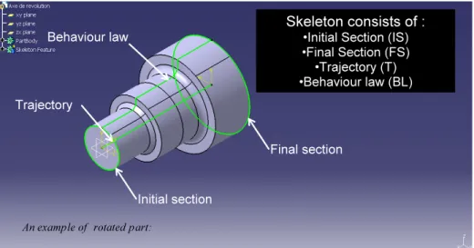
We suggest the representation of standards features by a skeleton forms. Hence, in figure 10, an initial section (IS), a final section (IF), a trajectory (T) and a behavior law (BL) represent a given feature.
Figure 10. Composition of features through rotated part.
Trajectory represents the path way between sections. Behaviour law represents evolution of section along the trajectory.
Type, Driving parameters and position within the product characterize each components of the skeleton. As we consider standard features, we will focus on simple features such as cylinders, cones ... Thus, circular, rectangular and triangular are types of sections. Linear are types of trajectory and behaviour law. For example, radius, length represent driving parameters of sections and trajectory.
Driving parameters and position within the product are the two most important characteristics. Indeed, driving parameters lead the geometry of the feature. We have regrouped Type and Driving parameters of each component in table 1.
Table 1. Driving parameters of components of skeleton features.
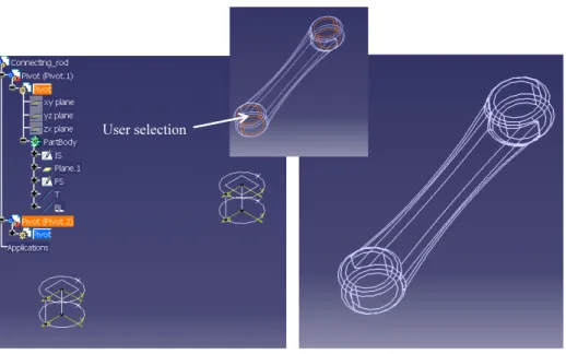
In order to position a given feature within the model, we consider that the origin of segmentation result is the same of the CAD environment. Each feature will be placed according to its position in the segmented 3D point cloud. In the scientific literature, the main proposal is to avoid user intervention. Our approach is different. It suggests that user will have two interfaces. The first represents a CAD environment of the reverse engineering process and the second is the segmentation result. Aided by our tool, the user lists the standards features within the product and uses the result of 3D point cloud segmentation to characterize them and to position them within the model. For example, if the IS are circular, KBRE will estimate its radius and its position in the wireframe of segmentation result. Finally, the set of standard features will be implemented in a first CAD shell. This tree is called a functional and structural skeleton of the part. Indeed, features represent the structure and the functional requirements of this part. We show on the figure 11, an example of structural and skeleton tree.
Figure 11. Functional and structural skeleton tree.
The functional requirement of the master rod illustrated on the figure 11 is to ensure two-pivot connections. Using the segmentation result on fig10.b, KBRE approach builds two pivot connection features in fig10.a.
3.4. Manufacturing process analysis within in the KBRE approach
The manufacturing process that has been used to create a part can be found by observing this one. The knowledge of this process can enable to improve a reverse engineering operation. Indeed, mould, casting extraction etc… leave traces on surfaces such as line of joint for mould process. Process rules above could be extracted from the part. According to expert, we can distinguish two kinds of rules: geometrical rules and expert rules. Geometrical rules influence the geometry of the part. Expert rules concern processes themselves. For stamping process, “Final model have draft angle” is a geometrical rule. Another example, for the hammer forging, “Homogenization of material flow” is an expert rule. Therefore, the database is built using these rules. Manufacturing processes are classified according to their type (primary, secondary and tertiary) [Ashby et al. 2004].
In Reverse Engineering, geometrical rules are more important than expert rules because of their influence on the geometry of the part. For each geometrical rule, one or more standard features, called manufacturing skeleton features, are referenced. User can select referenced manufacturing skeleton feature or add a new one.
Manufacturing process analysis is the first step. It allows to understand or to assume manufacturability of the part. All information issued will be integrated in the functional and structural skeleton tree. This first analysis contributes to create a CAD model using manufacturing features.
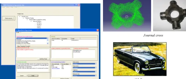
We are going to illustrate concept above by a use case of a journal cross of Peugeot 403 in Figure 12.
Figure 12. Manufacturing process step through study case of a journal cross.
After observation, it is possible to assume that the original journal cross was manufactured using forging process. In the database, a geometrical rule of this process could be “Entity enables to guide the coining”. A material removal maybe used for guide the coining. This is confirmed by the presence of a hole and user can create a manufacturing skeleton feature called “Material removal”. This feature is define according to each components (IS, IF, T, BL). By “clicking” the corresponding zone in the segmentation result, each parameter is valued.
Figure 13. CAD environment after user intervention
In figure 13, we show, left, the theoretical CAD model and, right, the result of segmentation. KBRE approach is implanted in a CATIA shell.
Our database is filled with most of the current manufacturing processes and lot of geometrical rules.
3.5. Analysis of the functional requirements of the part
As a part within a given product is used for a Reverse Engineering operation, knowledge about its function can enable to improve the rebuilt CAD model. This part was originally design to answer to a need. Thus, each part ensures one or more known functional specification. Consequently, environment of the part is known and can enable to explain the presence of certain features within the part.
Considering the R.E of an old product, the functional analysis of this one is essential to understand the part. The extraction of internal and external function participates to analyse in details the part. It was interesting to integrate this type of analyses in the KBRE tool. In our domain, only mechanical functions are needed because we consider mechanical part.
Now, functional analysis concerns mechanical analysis. It is required to know the mechanical environment of the part. Indeed, other parts of the product that are in direct mechanical connection with the considered part have to be known.
3.6. Mechanical connection and standard features.
In mechanical engineering, most of the mechanical connections between different parts are made using a set of standard features. As for manufacturing features, functional features will be chosen in a database.
KBRE approach suggests representing mechanicals connections through a “connection graph“.
We consider the case of study of a journal cross in figure 12. Two Yokes are the parts that compose the environment. Pivot connections are the two functional requirements. The both ensure two cylindrical surface contacts. The number of surface contacts reveals the number of standard features.
Figure 14. Functional requirements in KBRE Approach
We propose an interface that enables the creation of a connection graph. (fig 14). In a first step, user defines or assumes the different parts that compose the environment. In a second step, user defines the functional requirements. In the third step, user defines number of contact surfaces. Indeed, in this study, the part ensures two pivots connection and each of them needs two cylindrical contacts. Therefore, this information reveals that there are two cylindrical features for each pivot connection.
Concerning the positioning, a pivot connection with two cylindrical contacts is necessary coaxial. In the same way, a slider connection with four plans contact corresponds to two features that are at least parallel. Moreover, KBRE will integrate these constraints. In the
case of journal cross, the fact is that two cylinders, rebuilding using classical approach, have very little chance to be coaxial and even collinear because of the noise within the point cloud and the inaccuracy of the digitising device. Hence, functional requirements take into account this consideration. As done during manufacturing analysis, user defines the place of each feature. In the case of the journal cross, every feature corresponding to a contact surface is localized in the segmentation by the user. To avoid problem of placement, the first features will be placed with regard to the segmentation and the second feature with regard to the first feature. Moreover, the placement of the first are not fixed, the user can replace him it at any time.
3.7. The functional and structural skeleton of a part.
The functional and structural skeleton (FSS) of a part is an assembly of standard features listed by manufacturing analysis and functional requirements. In details, FSS are represented by a design tree of a CAD shell.
Figure 15. The functional and structural skeleton of the journal cross
Figure 15 represents a final version of functional and structural skeleton of the study case of a journal cross after all analysis step. IS, FS, T and BL components are represented by a sketches. Driving parameters of each component are valued and can be changed. CATIA V5 R16 is used as CAD environment. However, the design tree is adapted to this environment. In perspective, we aim to integrate the KBRE tool in a several CAD shell. Thus, the skeleton of a part is created. Bases of redesign are established.
The RE based on geometrical approach often provides a frozen and not reusable model. In this section, we focus on the classical design approach adapted to RE issue. In this approach, we define functions of the part based on the interaction of multiple expertises in order to identify and classify standard features. Standard features come from the used manufacturing process and functional requirements. In the scientific literature, this knowledge is required to establish a good reverse engineering. Moreover, it influences geometry of the part. Suggested KBRE is based on the KBE approach in the design process. Knowledge Based Reverse Engineering is adapted to the R.E problematic where there are needs of redesign. KBRE tool integrates analysis step that reveals standards features by considering the manufacturing process and the functional requirements.
Each standard features of the part is organized and gathered in a skeleton design called, in this section, the functional and structural skeleton. This one represents the structure of the body part. These features that compose the skeleton are the most important for the redesign.
KBRE tool is a hybrid approach that combines segmentation and “knowledge extraction”. By this approach, we do not avoid user interventions. In the KBRE tool, each feature is positioned according to the result of the edge based segmentation. Their placement is achieved by the user. Moreover, standard features are not fixed. At any time, the user can replace standard features.
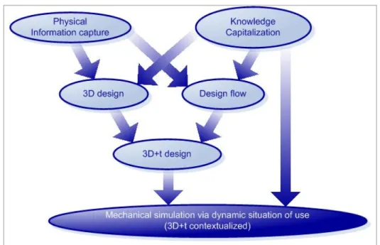
To sum up, KBRE methodology is a classical approach in Reverse Engineering that is improved by a knowledge extraction operation. We can represent suggested approach by the figure 16 that is an update of the figure 8 for the mechanical and industrial engineering domain (based on the definition of figure 1.).
Figure 16. Update of the figure 8 for the mechanical and industrial engineering domain.
IV. CONCLUSION
Augmented-Semantic models enable more efficient use of re-design models of existing objects. Based on fundamental theories related to skin and skeleton concepts, the combination of scanning and feature extraction methods lets obtain representations usable for future technological or analysis exploitations. Instead of obtained a classical triangle-based mesh, the proposed method lets combined existing CAD models with new virtualized objects models. This can be applied to most of the mechanical systems, and mainly the old ones that are not in use today. The basic idea to structure the numerical information in the same way that what is used for new object definition contributes to a better understanding and a better integration, as a mix, between actual and passed technologies and solutions. What has been presented also relates to a more global issue that also concerns the augmentation of semantic concerning the industrial and the socio-economical concepts, in a "Russian dolls" approach. This means that the proposed approach opens also new ways of multi-scale and multi-domain representations and analysis, including historical, technical, economical, social, societal aspects. A useful integration between these different layers lets appreciate the potentiality of the models and methods introduced in this chapter. The information used for the encapsulation of all the information is the key of the global coherency of the models. Some
simple examples have been shown but this method has been applied to more complicated systems whit multi-domain and multi-physics representations and analysis [Laroche 2009] [Laroche et al. 2008] [Laroche, 2008]. The future works concern both the extension of the knowledge integrated in the system that allows the feature recognition and rebuilding of the models and the robustness of the information. Several applications for the exploitation of the models using virtual reality environment are also in the scope of the next projects.
References
Alberts C., 2004, Surface reconstruction from scan paths, Future Generation Computer Systems, 20:1285-98.
Ashby M-F., Brechet Y-J-M., Cebon D., Salvo L., 2004, Selection strategies for materials
and processes, Materials and Design, vol 25, pp 51-67, 2004.
Benko P., Martin R., Varady T., 2001, Algorithms for reverse engineering boundary
representation models, Computer Aided Design, 33:839-51.
Benko P., Varady T., 2004, Segmentation methods for smooth point regions of conventional
engineering objects, Computer Aided Design, 36:511-52
Bernard A., Hasan R., 2002, Working situation model as the base of life-cycle modelling of
socio-technical production systems, CIRP Design Seminar, conference proceedings.
Bernard A., Laroche F., Ammar-Khodja S., Perry N., 2007, Impact of new 3D numerical
devices and environments on redesign and valorisation of mechanical systems, CIRP Annals
- Manufacturing Technology, Vol. 56/1/2007, ISSN 0007-8506, pp.143-148
Besl P., Jain R., 1988, Segmentation through variable order surface fitting, IEEE transaction on pattern analysis and machine intelligence, 10(2):167-91.
Bespalov D.,Yiu Ip C., RegliW C., ShafferJ., 2005, Geometric and Intelligent Computing
laboratory, Department of Computer Science, Department of Mechanical Engineering and
Mechanics, college of engineering, Drexel University, Philadelphia, 275-286.
Bonnot T., 2002, La vie des objets – d'ustensiles banals à objets de collection, Editions MSH, 244 p., ISBN 2735109348.
Durupt A, Remy S., Ducellier G., Eynard B., 2008, From a 3D point cloud to an engineering
CAD model: A knowledge product based approach for reverse engineering, Virtual and
Physical Prototyping 3 (2) 51-59
Eversheim W., Schenke F.-B., Weber P., 2000, Virtual engineering for an integrated product
and process development, CIRP Design Seminar, conference proceedings, 111-116
Fiorenzoli G., 2004, La 3D révèle le fonctionnement de l'automobile de Léonard de Vinci, Revue La Forge, n°18, pp.44-45 - http://brunelleschi.imss.fi.it/automobile/index.html
Han J., Pratt M., Regli W., 2000, Manufacturing feature recognition from solid models: A
Jeantet A., 1998, Les objets intermédiaires dans la conception. Eléments pour une sociologie
des processus de conception, Sociologie du Travail, pp. 291-316
Labrousse M., 2004, Proposition d'un modèle conceptuel unifié pour la gestion dynamique
des connaissances d'entreprise, PhD thesis, Ecole Centrale de Nantes, France
Laroche F., 2009, Quand l’industrie et le patrimoine ne font qu’un ! : Une expérience
scientifique originale réalisée par des étudiants en partenariat avec DCNS, Revue
Hippocampe, Journal de l’Association des Ingénieurs de l’Ecole Centrale de Nantes, n°61, mars 2009 – ISSN 1624-6683
Laroche F., Bernard A., Cotte M., 2008, Virtualization of ancient technical objects: a new
design process and its inter-disciplinary team, Conférence CIRP Design Seminar, Twente
University, Pays-Bas, 6 p. - www.cirp.net
Laroche F., 2008, Advanced Industrial Archaeology and Techno-Museology: A new virtual
life for industrial heritage, TICCIH Bulletin, number 41, summer 2008, ISSN 1605-6647,
pp.3-4 – www.mnactec.com/ticcih
Laroche F., 2007, Contribution à la sauvegarde des Objets techniques anciens par
l'Archéologie industrielle avancée, PhD thesis, IRCCyN laboratory, Ecole Centrale, Nantes,
France
Laroche F., Bernard A., Cotte M., 2006, Methodology for simulating ancient technical
systems, International Review of Numerical Engineering, Integrated Design and Production,
Vol. 2 n°1-2/2006, pp.9-28, Hermès-Science, Ed. Lavoisier, ISBN 978-2-7462-1679-2 - riin.revuesonline.com
Laroche F., Le Loch S., 2005, Culture technique et CAO par les machines anciennes, CETSIS, conference proceedings, 6 p.
Mohaghegh K., Sadeghi M-H., Abdullah A., 2006, Reverse engineering of turbine blades on
design intent, International Journal of Advanced Manufacturing Technolologies,
Springer-Verlag London,32:1009-1020
Monod J., 1970, Le Hasard et la nécessité, Éditions du Seuil, Paris, France, p.25
Patané G., Spagnuolo M., 2002, Multi-resolution and slice-oriented feature extraction and
segmentation of digitized data, SM’02 conference, Saarbrucken, Germany: 305-12.
Rasse P., 1991, Communication et muséologie des techniques, REMUS, conference proceedings, ISBN 2-11-08753218-23
Rolland-Villemot B., 2001, Le traitement des collections industrielles et techniques, de la
connaissance à la diffusion, OCIM letter n°73, pp.13-18
Sapidis N., Besl P., 1995, Direct Construction of polynomial surfaces from dense range
Thompson W., Owen J., De St Germain H., Stark S., Henderson T., 1999, Feature based
reverse engineering of mechanical parts, IEEE Transactions on Robotics and Automation,
15(1):57-65.
Trika, S.N. and Kashyap, R.L., 1994, Geometric Reasoning for Extraction of Manufacturing
Features in Iso-Oriented Polyhedra, PAMI(16), No. 11, pp. 1087-1100.
Van Houten F.J.A.M., Kimura F., 2000, The virtual maintenance system: a computer-based
support tool for robust design, product monitoring, fault diagnosis and maintenance planning, CIRP Annals - Manufacturing Technology, 49/1, 91-94
VPERI., 2003, Virtual Parts Engineering Research Initiative, The final report, (http://www.cs.utah.edu/gdc/Viper/Collaborations/VPERI-Final-Report.doc)
Woo H., Kang E., Wang S., Lee K., 2002, A new segmentation method for point cloud data, International Journal of machine tools and manufacture, 42:167-78.
Yokoya N., Levine M., 1989, Range image segmentation based on differential geometry: A