HAL Id: hal-01004699
https://hal.archives-ouvertes.fr/hal-01004699
Submitted on 14 Mar 2018HAL is a multi-disciplinary open access archive for the deposit and dissemination of sci-entific research documents, whether they are pub-lished or not. The documents may come from teaching and research institutions in France or abroad, or from public or private research centers.
L’archive ouverte pluridisciplinaire HAL, est destinée au dépôt et à la diffusion de documents scientifiques de niveau recherche, publiés ou non, émanant des établissements d’enseignement et de recherche français ou étrangers, des laboratoires publics ou privés.
A device to measure the shrinkage and heat transfers
during the curing cycle of thermoset composites
Yasir Nawab, Nicolas Boyard, Pascal Casari, Frédéric Jacquemin, Vincent
Sobotka
To cite this version:
Yasir Nawab, Nicolas Boyard, Pascal Casari, Frédéric Jacquemin, Vincent Sobotka. A de-vice to measure the shrinkage and heat transfers during the curing cycle of thermoset composites. Advanced Materials Research, Trans Tech Publications, 2011, 326, pp.19-28. �10.4028/www.scientific.net/AMR.326.19�. �hal-01004699�
A device to measure the shrinkage and heat transfers during the curing
cycle of thermoset composites
Yasir NAWAB
1,2,a, Nicolas BOYARD
1,b, Vincent SOBOTKA
1,c,
Pascal CASARI
2,d, Frédéric JACQUEMIN
2,e1
Université de Nantes, Nantes Atlantique Université, CNRS, Laboratoire de Thermocinétique de Nantes, UMR 6607, La Chantrerie, rue Christian Pauc, BP 50609, 44306 Nantes cedex 3, France,
2Université de Nantes, GeM, UMR CNRS 6183 F44000, France
a
yasir.nawab@univ-nantes.fr, bnicolas.boyard@univ-nantes.fr, cvincent.sobotka@univ-nantes.fr,
d
pascal.casari@univ-nantes.fr, efrederic.jacquemin@univ-nantes.fr
Keywords: Thermoset composites, vinyl ester resin, cure shrinkage, dilatometry, PVT- α Mould
Abstract. Residual stresses development during manufacturing of composites depends mostly on
the shrinkage behaviour of the polymer matrix from the point where stresses cannot be relaxed anymore. The matrix shrinkage may have a thermal and/or chemical origin and can leads to dimensional instability, ply cracking, delamination and fibre buckling. The approaches for measuring cure shrinkage can be classified as volume and non-volume dilatometry. Each technique has corresponding advantages and drawbacks but volume dilatometry is the one that is mostly used. In the present article, we report a home-built apparatus, named PVT-α mould, on which temperature, volume change and reaction conversion degree are measured simultaneously for an applied pressure. It can also be used to study the composite during curing and for the bulk samples having several millimetre thicknesses. The instrument is preferred over other techniques as it works in conditions close to the industrial ones. This device was used to measure cure shrinkage of resin and thermoset composite material with different fibre fractions as a function of temperature and reaction conversion degree. The heat of cure of the resin measured by PVT-α mould was compared to the results obtained by DSC.
Introduction
Residual stresses development during manufacturing of composites depends mostly on the shrinkage behaviour of the polymer matrix from the point where shrinkage stresses cannot be relaxed anymore. The matrix shrinkage may have a thermal and/or chemical origin. Depending on the matrix, considered chemical shrinkage is a direct consequence of crosslinking of a thermosetting polymer, or the crystallization of semi-crystalline matrix. Resulting residual stresses can lead to dimensional instability, warpage, ply cracking, delamination and fibre buckling. The characterization of the shrinkage is thus of crucial interest for stress calculation and modelling purposes.
Several approaches are available for measuring cure shrinkage which can be classified mainly as volume dilatometry and non-volume ones [1]. In non-volume techniques, volume change is measured by measuring change of some other property which is related to volume change. Such measurements are obtained from one dimensional or possibly two dimensional strains in the material by means of a contacting or non-contacting transducer. Examples of instruments are rheometer [2, 3], pycnometer [3-5], fibre bragg grating[6], thermo mechanical analyzer[7-9], dynamic mechanical analyzer [10], ultrasonic waves [11]etc.
In volume methods the volume change is directly measured. The instruments based on volume dilatometry can be classified in three categories
• Plunger-type dilatometers
• Capillary type dilatometers
• Dilatometers based on gravimetric methods.
The capillary-type dilatometers [12, 13] are the simplest dilatometers and measure the cure shrinkage by determining the linear height change of a column of liquid such as mercury or water, which is connected to a reservoir of the liquid surrounding the test substance. However, they generally lack digital output of the volume change so the precision of the measurement is largely limited by the accuracy of visual observation. Also such instruments allow measurements under low pressure which do not correspond always to processing conditions. In addition, the adhesion of resin with the walls of capillary tube results in additional errors. So this method is restricted to slow reactions, low conversions and low viscosity systems.
The plunger-type dilatometer is the instrument works closest to industrial conditions. It uses something similar to a syringe to contain and pressurize the sample. The plunger position of the syringe is monitored to follow the volume change. This type of instrument is in use for a long time now. Many authors [14-19] used this instrument for the dilatometry of thermoset resins. For example, M. Kinkelaar developed plunger-type instrument in 1992 [18, 20]. The Sample was placed in PE bag and immersed in chamber of oil which was closed by a piston to record volume changes.
Traditionally, this kind of equipment measures only pressure, volume, and temperature. The degree of cure is generally measured separately by DSC, which tends to be prejudicial against a wholly accurate interpretation since the experimental conditions are not exactly the same. Moreover, these studies are frequently performed under isothermal curing conditions to avoid thermal expansion and generally at low temperature (30–85°C range) to slow the reaction rate down.
In the present study heat of cure, thermal dilation, chemical shrinkage of vinyl ester resin and glass/vinyl ester composite as function of temperature and degree of cure was measured by using PVT- α mould. Some of the results were compared to the results obtained by DSC (differential scanning calorimeter).
Description of PVT-α α α α Mould
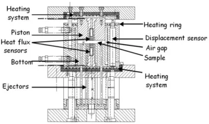
The PVT- α mould is a home-built apparatus [21, 22] where temperature, volume change and crosslinking conversion degree are measured simultaneously for an applied pressure. It is devoted to study neat resin and composite during curing cycle or post cure. In addition, experiments can be done on bulk samples (several millimetre thick and 40mm diameter). The instrument is preferred over other techniques as it works in conditions close to industrial ones (i.e. adjustable pressure up to 10MPa in moulding cavity and temperature up to 200°C). Fig. 1 shows the cross section view of the instrument. It consists of a piston which can move in a cylindrical cavity of stainless steel having internal diameter of 61mm. The mould is designed so that heat transfer in the sample placed in the cavity under piston is unidirectional i.e. through the thickness of sample.
Fig. 1. Cross section view of mould PVT-α
The heating is ensured by three heaters located at the top and bottom to heat the piston and cavity respectively. To limit temperature gradients through the thickness of sample, the heating rates are limited. This mould is placed between two plates of an electric press to move the piston. The pressure is adjustable in real time to keep it constant. Two heat flux sensors are placed in the bottom of the mould and in the piston. They are developed in our laboratory and each of them is composed of three thermocouples placed at different locations from the surface. Data treatment with a Beck inverse sequential algorithm provides temperature and heat flux density at the surface of the sensor. From the information obtained we can therefore determine the heat transfers between the sample and the mould. By neglecting the thermal gradients, heat flux measured ‘φ’ by the heat flux sensors is equal to
(1)
Where ‘m’ is the mass of sample, Cp is the specific heat of the resin and ∆H is the total heat
released during the curing cycle and α is the degree of cure.
From this we can also calculate the enthalpy and conversion degree associated to this chemical reaction.
Fig. 2. PVT-α Assembly
To study thermosetting polymers and their associated composites, it is necessary to place them in a sealed elastomer capsule (detailed in section 3) to avoid the jamming of the mould. A sample disk is thus compressed by the piston moving inside the cylindrical mould. The piston moves following the variations of the sample volume, which are recorded by LVDT-type displacement sensor with precision of 1µm with a limit of 10mm. The pressure is constant during the experiment and is assumed to be hydrostatic since the composite sample is placed in the deformable but
Piston
Cavity
Displacementsensor Ejector
incompressible elastomer cavity. Thus, the surface of the elastomer on which the pressure is applied does not vary. As a consequence, the measured thickness is directly related to the sample volume and its variations. The cooling system consists of compressed air circuiting in the top and in the bottom of the mould.
Material
In the present study the vinyl ester resin (DERAKANE MOMENTUM 411-350 epoxy vinyl ester) was used with 0.05% wt. of Catalyst (Cobalt Naphthenate ) and 1% wt. of initiator (NOROX MEKP-925H Methyl ethyl ketone peroxide (MEKP)). Glass fabric (300 GSM) was used as reinforcement for composite fabrication.
The elastomer capsule consists of two parts; a pan and a lid. This facilitates placement of fibers in the capsule in case of composite. In case of testing the neat resin, the both parts are sealed with a silicon-based adhesive. In case of composite the circular plies of reinforcements are cut and placed in the pan before sealing. Resin is then injected thanks to a specific set-up developed in the laboratory using syringes and vacuum pump.
Fig. 3. Heat Flux curves from PVT- α
On the other hand a vacuum pump through a syringe is connected to suction needle which ease the infusion and avoid air bubbles. Capsule is then placed in PVT- α for dilatometry experiment. Care is taken to keep the process as quick as possible to avoid the beginning of the reaction outside the mould since it is a low temperature polymerization resin. However it still takes about 10 minutes after preparation (i.e. mix initiator and catalyst) of resin to start PVT-α experiment.
Results and Discussion
The following cycle was used for the scanning of samples with PVT-α mould Equilibrate at 25°C Isothermal step for 2 min
1. Heating up to180°C at 4°C/min
2. Isothermal step for 10min at 180°C 3. Cooling to 20°C at 4°C/min. 4. Isothermal step for 10 min.
The acquisition system records the temperatures given by the six thermocouples with respect to a cold junction (its temperature is recorded) and the signal of the displacement sensor. After data treatment the total heat flux density and the thickness variation are obtained. However, they have to
be reprocessed to take into account possible heat losses of the mould but also thermal expansion of the LVDT sensor, the elastomer and the mould. This step is done by applying the same temperature cycle to an aluminium disc in an elastomer capsule, for which we know exact thermal expansion, density and specific heat. We can then deduce the real heat flux density (φ) and the displacement response associated to the sample only. An example of result (heating cycle only) for the resin is presented in fig.3. In the beginning when the reaction did not started, an endothermic effect can be observed but with time as temperature increased the reaction speeded up resulting in exothermic peak with maximum value of 6440 w/m². After about 1300 second the resin is cured completely or reaction became very slow so the exothermy becomes negligible. In the isothermal step flux curve returns to zero level showing that there is no more heat release or reaction.
Area under heat flux curve with respect to time gives total heat of reaction which was found to be ∆H =332 J/g. Note that a sigmoid baseline is used to take into account specific heat variation during the crosslinking. The resin was also scanned on DSC (Q-200, TA instruments) for the same range of temperature and the reaction enthalpy was found equal to 340 J/g. The difference between these values may be due to the uncertainties associated to these results and/or to heat flux released before the beginning of the PVT-α experiment.
The degree of reaction/cure (α) is given as follow
(
2)Where ‘∆Htot’ is the total heat of reaction.
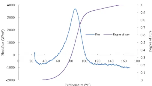
Fig. 4. Heat flux and degree of cure as function of temperature recorded with the neat resin
Fig. 4 shows the heat flux and degree of cure curves as a function of temperature. It can be observed that as temperature increases the reaction starts rapidly (as soon as T = 45°C) and the heat flux is released in a short temperature range. When the system reaches the glass transition temperature the reaction did not stop but becomes very slow as the system is heated constantly and continued like this until complete curing of resin. This effect can be observed at the end of flux curve in the form of minute waviness.
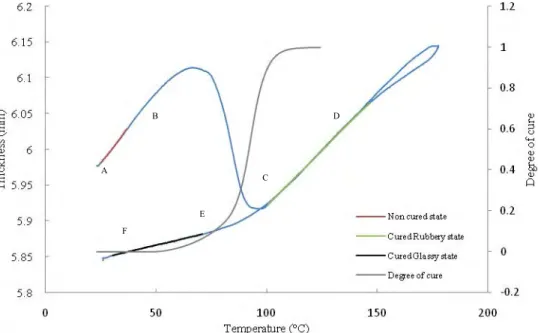
Fig. 5. Variation of thickness of resin sample with respect to temperature and degree of cure
Cure shrinkage determination
As previously explained the effects of temperature on the mould, the elastomer and on the sensor are to be subtracted from the displacement sensor response. That is why an aluminium standard disc with known properties was scanned. As the pressure is applied during the whole experiment, the cylindrical sample kept a constant diameter thanks to the deformability of the elastomer and, consequently, the sample volume change induces only a change of the sample thickness. Thus, one can expect that resultant coefficients of thermal expansion and chemical shrinkage will also be the volume coefficients.
Fig. 5 shows the variation of thickness of resin sample with temperature and degree of cure. During the heating cycle two phenomena are involved in the evolution of this curve
1- Thermal expansion/contraction due to temperature rise and 2- Cure shrinkage due to polymerization of resin.
While during cooling cycle the only prominent phenomena will be the thermal contraction. This can be understood by considering both the curves of displacement and conversion degree. At the beginning (A-B part), the displacement curve is linear versus temperature. The chemical reaction does not start yet or is not very significant. So the slope of graph in this region will give coefficient of thermal expansion of uncured neat resin using the classical definition .
It is found to be equal to CTEuncured = 6.37.10-4 °K-1. In the region between the points B and C, a
phenomenon of chemical shrinkage due to significant cure of resin (see the conversion degree curve) also appears in addition to thermal expansion and tends to decrease the final thickness till the point C where the resin is close to be fully cured. After the point C the only prominent effect is again thermal expansion so a linear behaviour of the displacement curve is observed between points C and D and its slope provides the coefficient of thermal expansion of cured resin in rubbery state (as temperature is above Tg). The value of thermal coefficient was found to be
CTEcured,rubbery=5.33.10-4°K-1.
During cooling step, the thickness curve is superimposed between C and D with the one plotted during the heating step. It implies that the contraction coefficient is equal to the coefficient of expansion. However, between points D and E the resin goes through the glassy state since the slope of the thickness A B C D E F
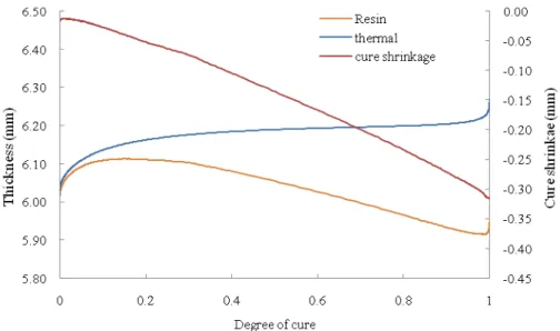
Fig. 6. Change of Chemical shrinkage and thermal expansion with degree of cure
curve changes to become smaller. Below Tg (i.e. Tg = 118.9°C determined from DSC experiment), coefficient of expansion is equal to CTEcured,glassy = 1.24.10-4 °K-1. The difference between points A
and F gives the total shrinkage of material after polymerization and cooling at that temperature. We find that the global shrinkage at room temperature is -2.1vol %. In order to get value of thermal expansion coefficient in region B-C, a simple mixing law (eq 3) can be used
CTE=CTEuncured.(1-α)+α. CTEcured,rubbery (3)
Where α is the degree of cure, CTE is coefficient of thermal expansion at any point. By using calculated value of CTE, thickness variation due to thermal origin can be found. The contribution of the polymerization to shrinkage can be calculated by subtracting the contribution of the thermal effect from the experimental thickness curve [21 - 22]. Fig. 6 shows the graph of total thickness (resin) variation with degree of cure. The curve ‘thermal’ corresponds to thickness after variation due to change in temperature and ‘cure shrinkage’ curve which is difference of total thickness and thermal contribution corresponds to thickness changed due to cure shrinkage of resin. It can be observed that the cure shrinkage varies linearly with degree of cure. The slope of cure shrinkage when divided by initial thickness results in a constant said to be ‘volume coefficient of chemical shrinkage (CCS)’. In present study for vinyl ester resin the value of CCS was found as 0.068.
Fig. 7. Variation of chemical shrinkage of composite with degree of cure for different fibre fractions
Cure shrinkage of composites
For making composite, glass fabric of 300 g/m² was used to prepare12 and 16 circular plies resulting in 20 and 31% fibres by volume, respectively. The resin was injected into a capsule manually filled with the fabric plies. PVT-α experiment were done using the same curing cycle as the one previously detailed for neat resin. Fig. 7 shows the results of composite chemical shrinkage variation with degree of cure. The cure shrinkage is converted to 100% mass of resin for the purpose of comparison. It can be observed that the shrinkage behaviour of composites is linear in the beginning of reaction but after achieving certain degree of cure it deviates and become not linear. By increasing fibre fraction the final values of shrinkage decreases and the curve shape changes at the end of the crosslinking. Hypothesis can be made that the fibres hinder the shrinkage of resin that may lead to increase residual stresses.
Conclusion and Prospective
This study shows that PVT-α mould is a useful device which is more versatile than a classical dilatometer. It measures simultaneously the degree of cure and variation of volume. So there is no need of DSC for measuring separately the reaction kinetics. PVT-α was also used for measuring dimension changes of composite which is not possible with other conventional instruments.
By using mould PVT-α, it was found that for vinyl ester resin the chemical shrinkage is a linear function of degree of cure and the value of volume coefficient of shrinkage was found as 0.068. It was found that the curing shrinkage in composite form is non-linear contrarily to curing shrinkage of resin alone. It was also established that ultimate shrinkage decreased with increasing fibre fraction in composite. This may results into higher residual stresses.
References
[1] Li, C., et al., In-situ measurement of chemical shrinkage of MY750 epoxy resin by a novel gravimetric method. Composites Science and Technology, 64(1) (2004) 55-64.
[2] Haider, M., P. Hubert, and L. Lessard, Cure shrinkage characterization and modeling of a polyester resin containing low profile additives. Composites Part A: Applied Science and Manufacturing, 38(3) (2007) 994-1009.
[3] Shah, D.U. and P.J. Schubel, Evaluation of cure shrinkage measurement techniques for thermosetting resins. Polymer Testing. 29(6) 629-639.
[4] Cook, W.D., M. Forrest, and A.A. Goodwin, A simple method for the measurement of polymerization shrinkage in dental composites. Dental Materials, 15(6) (1999) 447-449.
[5] Schoch, K.F., P.A. Panackal, and P.P. Frank, Real-time measurement of resin shrinkage during cure. Thermochimica Acta, 417(1) (2004) 115-118.
[6] Parlevliet, P.P., H.E.N. Bersee, and A. Beukers, Measurement of (post-)curing strain development with fibre Bragg gratings. Polymer Testing, 29(3) (2010) 291-301.
[7] Hong, Y., G.M. Subodh, and W. Ee Hua, Observations of Gelation and Vitrification of a Thermosetting Resin during the Evolution of Polymerization Shrinkage. Macromolecular Rapid Communications, 26(18) (2005) 1483-1487.
[8] Tai, H.J. and H.L. Chou, Chemical shrinkage and diffusion-controlled reaction of an epoxy molding compound. European Polymer Journal, 36 (2000) 2213-2219.
[9] Zarrelli, M., I.K. Partridge, and A. D'Amore, Warpage induced in bi-material specimens: Coefficient of thermal expansion, chemical shrinkage and viscoelastic modulus evolution during cure. Composites Part A: Applied Science and Manufacturing, 37(4) (2006) 565-570.
[10] Lange, J., et al., Residual stress build-up in thermoset films cured above their ultimate glass transition temperature. Polymer, 36(16) (1995) 3135-3141.
[11] Hoa, S.V., P. Ouellette, and T.D. Ngo, Determination of Shrinkage and Modulus Development of Thermosetting Resins. Journal of Composite Materials, 43(7) (2009) 783-803. [12] Arthur, W.S.a.J.P.A., Dilatometry on Thermoset Resins Naval Research Laboratry 1991. [13] Yan-Jyi, H. and L. Chiou-Ming, Volume shrinkage characteristics in the cure of low-shrink unsaturated polyester resins. Polymer, 37 (1996) 401-412.
[14] Li, W. and L.J. Lee, Low temperature cure of unsaturated polyester resins with thermoplastic additives: I. Dilatometry and morphology study. Polymer, 41(2) (2000) 685-696. [15] Madhukar, M.S., M.S. Genidy, and J.D. Russell, A New Method to Reduce Cure-Induced Stresses in Thermoset Polymer Composites, Part I: Test Method. Journal of Composite Materials,
34(22) (2000) 1882-1904.
[16] Russell, J.D., et al., A New Method to Reduce Cure-Induced Stresses in Thermoset Polymer Composites, Part III: Correlating Stress History to Viscosity, Degree of Cure, and Cure Shrinkage. Journal of Composite Materials, 34(22) (2000) 1926-1947.
[17] Zoller, P.B., P.; Pahud, V.; Ackermann, H., Apparatus for measuring pressure-volume-temperature relationships of polymers to 350 °C and 2200 kg/cm2. Rev.Sci.Instrum., 47(8) (1976) [18] Mark, K., M. Shailesh, and L.J. Lee, Dilatometric study of low profile unsaturated polyester resins. Polymer Engineering & Science, 1995. 35(10): p. 823-836.
[19] Ramos, J.A., et al., Cure kinetics and shrinkage model for epoxy-amine systems. Polymer,
46(10) (2005) 3323-3328.
[20] Mark, K. and L.J. Lee, Development of a dilatometer and its application to low-shrink unsaturated polyester resins. Journal of Applied Polymer Science, 45(1) (1992) 37-50.
[21] Boyard, N., et al., Behaviour of a moulded composite part: Modelling of dilatometric curve (constant pressure) or pressure (constant volume) with temperature and conversion degree gradients. Composites Science and Technology, 67(6) (2007) 943-954.
[22] Boyard, N., et al., Analysis and modeling of <I>PVTX</I> diagram of an unsaturated polyester resin, thermoplastic additive, and mineral fillers blend. Journal of Applied Polymer Science, 88(5) (2003)1258-1267.