HAL Id: hal-01199467
https://hal-mines-paristech.archives-ouvertes.fr/hal-01199467
Submitted on 15 Sep 2015HAL is a multi-disciplinary open access archive for the deposit and dissemination of sci-entific research documents, whether they are pub-lished or not. The documents may come from teaching and research institutions in France or abroad, or from public or private research centers.
L’archive ouverte pluridisciplinaire HAL, est destinée au dépôt et à la diffusion de documents scientifiques de niveau recherche, publiés ou non, émanant des établissements d’enseignement et de recherche français ou étrangers, des laboratoires publics ou privés.
Shaping of a dual membrane SOFC and first
electrochemical tests in a dedicated 3- chamber set-up
David Masson, Francesco Perrozzi, Paolo Piccardo, Massimo Viviani, Claire
Pilot, Zdravko Stoynov, Daria Vladikova, Anthony Chesnaud, Alain Thorel
To cite this version:
David Masson, Francesco Perrozzi, Paolo Piccardo, Massimo Viviani, Claire Pilot, et al.. Shaping of a dual membrane SOFC and first electrochemical tests in a dedicated 3- chamber set-up. SOFC-XIV: Anodes 2, Jul 2015, Glasgow, United Kingdom. �10.1149/06801.1969ecst�. �hal-01199467�
Shaping of a Dual Membrane SOFC and First Electrochemical Tests in a Dedicated 3 Chamber Set-Up
D. Massona, F. Perrozzibc, P. Piccardob, M. Vivianic, C. Pilota, Z. Stoynovc,D. Vladikovac, A. Chesnauda, A. Thorela
a
Centre des Matériaux, MINES-ParisTech, PSL, UMR CNRS 7633, BP 87, 91003 Evry Cedex, France
b
DCCI – Univ. Genova, via Dodecaneso 31, I-16146 Genoa, Italy c
IENI, Consiglio Nazionale delle Ricerche, Via E. De Marini, 6 , I-16149 Genoa, Italy d
Institute of Electrochemistry and Energy Systems – Bulgarian Academy of Sciences, 10 Acad. G.Bonchev St., Sofia 1113, Bulgaria
The present paper offers a discussion about an innovative dual membrane fuel cell concept IDEAL-Cell operating between 600 °C-700 °C. It is based on the junction of SOFCs anodic part with PCFCs cathodic part through a mixed H+ and O2- conducting porous membrane. This concept was successfully proved and developed during the 4 years of a FET-Energy/FP7 project, through the collaboration between 10 European research and technological institutes. After two stages of development, respectively the proof of concept and the realization of an optimized lab-scale cell, the concept has evolved to a simplified design, called “monolithic”, in which the mixed H+ and O2- conduction of BCY15is exploited for the fabrication of all the cell components. With the reduction of chemical gradients and thermal expansion mismatches, the cell durability is potentially enhanced. Furthermore, the shaping, the microstructure and the catalytic properties of the central membrane (CM) have been improved by structuring the central membrane with a Ni foam or by including Pt nano-particles. This work presents a complete study of the permeability of the central component of this concept in view of a reversible SOFC/SOEC operation, and the preliminary results obtained on this new Ni-foam based architecture by using a 3-chambers set-up (Real Life Tester) to determine the electrochemical performances of the cell in real operating conditions.
Introduction
Context
High temperature fuel cells are promising power generating systems, which are generally based on anionic solid conductors (SOFC) and most recently on protonic conductors (PCFC). The operating temperature of SOFC is usually high (> 900 °C) for a higher electrolyte ionic conductivity. This operating temperature induces several pitfalls for the materials reactivity and stability, requires complex glass sealing, and enhances the stack
ageing when cycling. These difficulties can be minimized by reducing the operating temperature to 600-700 °C, but this will affect significantly the ionic conductivity which will have to be compensated by changing the electrolyte material and drastically decrease the electrolyte thickness. PCFCs have been recently developed and offer alternative materials solutions and ionic conduction mechanisms. Perovskite based proton conductors materials have been widely studied, especially yttria-substituted BaCeO3 (BaCe1-xYxO3–δ) which exhibits a high level of protonic conduction below 700 °C under H2 and/or water containing atmosphere.
Standard SOFC and PCFC designs induce water formation respectively at the anode and cathode sides where they exhibit significant concentration overpotentials. Moreover, in both cases the formation of water at high temperature, associated either with hydrogen (SOFC) or oxygen (PCFC) will strongly affect the metallic interconnects durability. Later, a new SOFC design was proposed (named IDEAL-Cell) based on a dual membrane with mixed protonic and anionic conduction which combines the benefits of state of art PCFC and SOFC devices while avoiding their disadvantages due to the presence of water at the electrodes (1-6). It is made of the anode/electrolyte part of a PCFC and of the cathode/electrolyte part of a SOFC, sandwiching a porous central membrane wherein the water is formed by the combination of H+ and O2- ions. Water is formed neither at the anode nor at the cathode, and the cell is made of 3 independent chambers for oxygen, hydrogen and water respectively. This 3-chamber symmetrical concept is particularly suitable for a reversible operation (Fuel cell/Electrolyser = FC/EL) (7). The original IDEAL-Cell concept has been developed from an anode-supported cell configuration, using a composite material for the central membrane BaCe0.85Y0.15O3–δ - Ce0.85Y0.15O2– δ (BCY15-YDC15) to ensure respectively the protonic and the anionic conductivity (Figure 1).
Figure 1. The IDEAL Cell Concept.
Objectives
Since BCY15 exhibits at 600-700 °C a comparable and high level of oxygen and proton conduction (8), the central membrane could be drastically simplified by using a single material with mixed conductivity (BCY15) in place of the former composite (BCY15-YDC15). To facilitate the shaping, to enhance the catalytic properties and to maintain a high level of porosity to ensure either an efficient evacuation of water (SOFC mode) or incoming flux of water (SOEC mode), the concept was extended in the present work by the integration of a metallic foam in the central membrane of the cell (Figures 2 and 3).
Figure 2. IDEAL Cell evolution; (a) the dual membrane, (b) the monolithic and (c) the nickel foam concepts.
Figure 3. The (a) SOFC and (b) SOEC modes.
This preliminary work was specifically focused on 2 key functional characteristic of the central membrane for a reversible operation, the porosity and the conductivity, studied specifically and independently by permeability measurements and impedance spectroscopy (9,10), and then submitted in real operation conditions via a dedicated test bench (Real Life Tester RLT) which has been designed by the CNR and ErgoDesign specifically for a 3 chambers cell (Figure 4).
Figure 4. The Real Life Tester (RLT) for 3 chambers sample.
Experimental
Standard monolithic central membrane
The standard monolithic central membrane was made from BaCe0.85Y0.15O3-δ powder
(Marion Technologie batch #008) with different volume percentages (10, 20, 30 and 40 vol.%) of graphite (Timcal Group, Timrex KS6) and sintered-aids (ZnO from Alfa Aesar,
99.9%, 200 mesh powder). Powders were mixed with a planetary ball milling for 4 hours with a speed of 500 rpm. 2.0 g of powder were cold-pressed at 2 kg.cm-2. Samples were treated at 750 °C for 2 hours in air to remove the graphite, and sintered at 1400 °C for 5 hours in air.
Ni-foam based monolithic central membrane
Ni-foam based monolithic central membrane was produced from BaCe0.85Y0.15O3-δ
(CerPoTech) mixed with 20 vol.% of graphite and sintered-aids. Powders were mixed with planetary ball milling for 4 hours with a speed of 500 rpm. The nickel foam provided by Alantum, exhibits an initial porosity of 98 vol.% with an average mesh size of 0.5 mmand a material purity of 99.97% of nickel. The foam was inserted in the center of the sample during the cold-pressing process, and pressed. To ensure an appropriate open porosity inside the CM, the foam was laminated at 1 kg cm-2 and 2 k .cm-2.Then, the samples were treated at 750 °C for 2 hours in air to remove the graphite and pre-sintered at 1100 °C under H2 (5 vol.%)-Ar for 5 hours.
Standard monolithic and Ni-foam based monolithic central membrane sandwiched with BCY15 electrolytes
Symetrical BaCe0.85Y0.15O3-δ electrolytes have been coated on the standard monolithic
and Ni-foam based monolithic central membranes. Inks were made from another BCY15 powder coming from Marion Technologie (batch #007) which reveals a finer granulometry (d90[BCY-MT#008] = 4.08 µm vs d90[BCY-MT#007] = 0.71µm) and a better densification
rate. Sintered-aid was also added to the starting powder to decrease the sintering temperature. Screen printed electrolyte inks were realized from commercial binder, dispersant and solvent provided by AUREL. For dip-coating inks, ethanol was considered as solvent, polyninyl butyral (PVB) as dispersant and polytehylene glycol (PEG) as binder. Both inks were grinded with a planetary ball milling for 5 hours with a speed of 500 rpm. Screen printed electrolytes have been successfully realized on both sides with speed of squeegee of 100 mm min-1. For the dip-coated electrolytes, the central membranes were dipped into the electrolyte ink and slowly removed from the ink (5 mm min-1). All the final samples were dried overnight, treated at 350 °C for 2 hours under air, and sintered at 1400 °C for 5 hours under H2 (5 vol%)-Ar.
Full monolithic and Ni-based cells
Anode layer is composed of an equivolume cermet of BCY15-NiO respectively from BaCe0.85Y0.15O3-δ (Marion Technologie batch #008) and NiO (Novamet, high purity Type
A). The ink was prepared using commercial binder, dispersant and solvent provided by AUREL. Cathode layer is made an equivolume mixture of BaCe0.85Y0.15O3-δ (Marion
Technologie batch #008) and La0.60Sr0.40Co0.20Fe0.80O3-δ (LSCF48 Marion Technologie).
The ink is also composed of commercial binder, dispersant and solvent provided by AUREL screen printing device. Both electrode inks were mixed with a planetary ball milling for 4 hours with a speed of 500 rpm. 10 µ m electrodes layer were first coated using a AUREL C900 screen printer with speed of squeegee of 100 mm min-1. In order to increase the final thickness, bar coated electrodes have been realized using Elcometer 4340 Automatic Film Applicator. Anode layers were treated at 350 °C for 2 hours under air,
sintered and reduced at 1300 °C under H2 (5 vol.%)-Ar. Cathode layers were separately
fired at 350 °C for 2 hours in air, and sintered at 1100 °C for 5 hours in argon.
The impedance measurements were performed on half cells with different porosity of the BCY15 pellets (diameter 20 mm and thickness about 1mm) and Pt electrodes. They were carried out on Solartron 1260 FRA in temperature interval 100-750 oC and frequency range from 10 MHz down to 1 mHz with density 5 points/decade, applying different modes and amplitudes of the AC signal (8). For registration and evaluation of the mixed ion conductivity the measurements were performed at OCV in air (50 NmL min-1) and in wet (3% H2O) hydrogen (50 NmL min-1). The gases and water vapor permeability within the
porous CM were studied on specially designed testing system by measurement of the gas pressure P (mm H2O) as a function of the flow qflow [ml/min] penetrating through CM
samples with different porosity (9). The dielectric permittivity measurements were performed in frequency range 1 MHz down to 0.01 Hz with 1V amplitude of the AC signal. In this case the BCY15 sample was connected in the experimental rig as a capacitor.
Full cells were tested in a rig called ErgoDesign “Real Life Tester” (RLT). Such rig is designed to host central membrane cells. It is constituted by three chambers: two of them exposing each face of the sample to a specific atmosphere, allowing experiments in dual atmosphere. The third chamber is external and surrounds the previous two permitting the employment of a third atmosphere and allows to remove the H2O produced by the cell or to
provide it in electrolysis work mode. Electrochemical measurements were done using a quadripolar system made by Pt wires connected to an IviumStat analyzer and data was collected with IviumSoft software. Two different thermocouples monitor constantly the temperature on the two faces of the cell.
Results and discussion
The full permeability and conductivity study has been carried out on standard monolithic central membranes and cells, while preliminary Ni-foam based monolithic cells have been used for testing the 3-chamber set-up.
Standard monolithic cells
BaCe0.85Y0.15O2.925 is a good proton conductor (12). Under humidified hydrogen
atmosphere protonic defects are formed by dissociative absorption of water in the presence of oxygen vacancies. Water vapor dissociates into a hydroxide ion, which fills an oxide-ion vacancy, and a proton that forms a covalent bond with lattice oxygen, i.e. two proton defects are created stoichiometrically. However, the presence of oxide-ion vacancies could be regarded as a precondition for oxide ion conductivity. There are few papers on mixed oxide conductivity: t is reported that the increase of the substitution level is in favor of the mixed conductivity. For x = 0.10 (BCY10) proton conductivity is predominant up to 700
o
C, while for x = 0.25 (BCY25) mixed conductivity is registered above 550 oC (13,14). These results are based on conductivity measurements at different temperatures and atmospheres, as well as on the more precise measurements of proton and oxide ion transport numbers and water permeation. The idea for eventual mixed ionic conductivity brought to the idea for the monolithic approach. The first tests of BCY conductivity in hydrogen and in air in symmetrical half cells confirmed the high proton and oxide ion
conductivity at operating temperatures (13). Since BCY15 has the natural property to split water, it is supposed that the monolithic design will have also a good performance as electrolyzer.
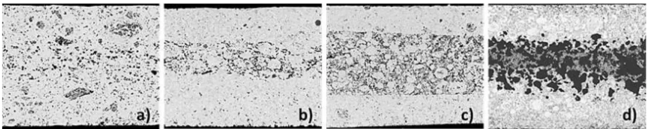
Obviously the challenging component in the dual membrane FC design is the CM, since it needs the optimization of different processes with contradictory initial requirements: (i) water vapor formation / evacuation or injection / splitting, for which a porous structure is needed and (ii) high mixed ion conductivity, favored by higher density, higher volume fraction and lower tortuosity of the solid phase. Obviously a compromise is required, since the increase of porosity improves the water permeability and increases the number of reaction sites, but also decreases the conductivity. Studies of water behavior in the CM are also important for both fuel cell and electrolyzer operation modes. Thus in addition to the optimization of the CM in respect to conductivity and permeability, the CM should be optimized in respect to thickness and microstructure, since it becomes a chemical reactor where water is produced or split. The central membrane porosity is the key characteristic for the management of water in both operation modes. Back-scattered SEM images on polished cross-section samples of monolithic central membrane with different volume fractions of pore formers show with no surprise that that the porosity increases with the amount of pore formers (Figure 5).
Figure 5. Central membrane porosity sintered at 1400 °C for 5 hours: (a) no-graphite, (b) 10 vol.% graphite, (c) 20 vol.% graphite and (d) 30 vol.% graphite.
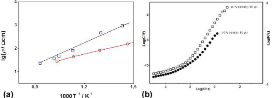
Porosity analyzed as percentage of the CM volume is insufficient for characterization of the CM. The geometry and distribution of the pores are also important, as well as the behavior of the interface pore surface/water. The combination of conductivity, gas permeability and dielectric permittivity studies is a challenging attempt for a deeper insight into the complex processes in the CM, needed for its technological optimization. Logically, the resistivity measurements of porous membranes with different porosities showed a clear decrease of the conductivity with the increase of porosity; a reasonable compromise is seen for 30 vol.% porosity (Figure 6). It is interesting to note that in oxygen BCY15 shows a better performance than the classical oxide ion conductor YDC15 (Figure 7a).
At room temperature a wet BCY15 sample can be regarded as a non-polar dielectric ceramic matrix in which a polar dielectric liquid is introduced. Such systems can be studied by dielectric permittivity spectroscopy, which is a branch of the Impedance Spectroscopy applied for dielectrics permittivity properties studies. In this case the admittance Y can be presented as (10):
Where ωC'' can be regarded as dielectric conductivity, which involves the energy dissipative effects as ohmic conductivity, dipole’s reorientation losses in electric field and others, while C' is directly related to the dielectric permittivity, i.e. to the polarization ability. 1,0 1,2 1,4 1,6 1 2 3 lg ( ρ / Ω c m ) 1000T -1 / K-1
Figure 6. Arrhenius plots of BCY15 resistivity: 30% porosity measured in dry air (●) and wet hydrogen (■).
Figure 7. (a) Arrhenius plots resistivity for BCY15 () with 12% porosity and YDC15 (□)
and (b) frequency dependence of C' in BCY15 with different porosity and the same pore former.
An illustrative form of presentation is the log(C')/log(f) plot where f is the frequency (Figure 7b). The first studies of water behaviour in porous BCY15 membrane performed by complex permittivity measurements registered gigantic enhancement of the real component of the capacitance (10). This phenomenon was associated to the formation of semi-liquid dipole layer. The configuration of electrochemically active volumetric layer at the pores surface in the CM would additionally improve the performance of the monolithic dual membrane FC in both FC and EL modes. Our experiments show that the capacitance enhancement is influenced by the pore geometry, which is related to the developed free surface in the volume of the CM, and the pores tortuosity, which determines the ability of the sample to be externally watered. As it can be seen in Figure 8a, the enhancement of C' is bigger for the sample with higher porosity at one and the same quantity of introduced water. The results are in good correlation with the gas permeability measurements, first as a function of the volume fraction of pores (Figure 8a) and second as a function of the gas molecular weight (Figure 8b), which can be regarded also as a very sensitive approach for evaluation of the gases pathway tortuosity in respect to the porous structure.
Figure 8. (a) Hydrogen permeability of CMs with different porosity at room temperature and (b) Gases permeability measurements in the CM with 50 vol.% porosity at room temperature.
In addition to measurements of water vapor permeability in the central membrane, the developed method for gases permeability testing may be applied for porosity and tortuosity estimation, since gases are less resistive to penetration through the porous ceramic media. Thus although performed at room temperature, the combination of gas permeability and dielectric permittivity measurements can be very informative and predictive for the optimization of the CM, as well as of the electrodes microstructure.
Ni-based monolithic cells
The best pressing compromise for the Ni foam central membrane was obtained for 1 kg cm-2, which led to an initial porosity of 57.5 vol.%, and to a final porosity of 62 vol.% after BCY15 impregnation with 20 vol.% of graphite, with an average pore size diameter of 1.85 µm. The screen printed BCY15 electrolytes are dense and 30 µm BCY15 thick, but clearly shows reactivity with NiO. Sintered screen-printed electrodes present a low thickness of 20 µm. For the second cell, the dip-coated electrolytes are 90% dense for a thickness of 40 µm. The bar coated electrodes gave an average thickness of 50 µm without any reactivity between consecutive layers (Figure 9).
A stable but low OCV (0.550 V), probably due to some leakage and non optimized gas mixture, was obtained at 747 °C with a wet-H2 flow of 30 Nml min-1 and an air flow of 75
Nml min-1 and N2 flow in the third chamber of 80 Nml min-1. The cell was polarized by
applying increments of intensity from 0.0 to 1.1 mA.
Figure 9. BSE-SEM images of (a) laminated nickel foams at 1 kg cm-2, (b) screen-printing Ni-foam cell, (c) dip-coated Ni-foam cell.
The I-V curve exhibits a wavy shape due to the incremental nature of the applied intensity: at each intensity increment there is a competition between the speed at which water is created, hence blocks at first the reaction (I and V decrease), and the speed at
which water is evacuated (V still decreases, but I recovers). It is anticipated that the negative and positive slopes of the I-V waves are closely related to the porosity morphology (volume fraction, tortuosity, shape) and could give interesting information about the kinetic of mechanisms associated with water (Figure 10).
Figure 10. Cell voltage curve vs. current density obtained at 747 °C for a Ni-foam IDEAL-Cell.
Conclusion
These preliminary results confirm that the optimization of SOFC performances is always a matter of compromise between contradictory requirements. It was shown on innovative configurations that the permeability should always be considered along with the ion conductivity. As a preliminary result, the integration of a metallic foam within the dual membrane of this new architecture made the control of a high open porosity easier. The different testing set-ups built for this study were proved to perform well and give novel information still under scrutiny.
Acknowledgement
All the coworkers from the, CNR (Italy), University of Genova (Italy), Bulgarian Academy of Sciences (Bulgaria) and ARMINES (France) who have been involved in the framework of the project IDEAL-Cell are gratefully acknowledged for their contribution to this work. The research leading to these results has received funding from the European Union’s Seventh Framework Programme (FP7/2008-2011) under grant agreement N°213389 and from Bulgarian NSF under grant N° E02/3/2014.
References
1. A.S. Thorel, J. Abreu, S.A. Ansar, A. Barbucci, T. Brylewski, A. Chesnaud, Z. Ilhan, P. Piccardo, J. Prazuch, S. Presto, K. Przybylski, D. Soysal, Z. Stoynov, M. Viviani, D. Vladikova, J. Electrochem. Soc., 160(4), F360-F366 (2013).
2. T. Ou, F. Delloro, W.G.Bessler, A.S. Thorel, C. Nicolella, J. Electrochem. Soc.,
3. A.S. Thorel, A. Chesnaud, M. Viviani, A. Barbucci, S. Presto, P. Piccardo, Z. Ilhan, D.E. Vladikova, Z. Stoynov, S.C. Singhal and H. Yokokawa (Eds.), in Solid Oxide
Fuel Cells XI (SOFC-XI), The Electrochemical Society Proceedings Series, ECS Transactions, 25(2), 753 (2009).
4. S. Presto, A. Barbucci, M. Viviani, Z. Ilhan, S.A. Ansar, D. Soysal, A. Thorel, J. Abreu, A. Chesnaud, T. Politova, K. Przybylski, J. Prazuch, Z. Zhao, D. Vladikova, Z. Stoynov, S.C. Singhal, H. Yokokawa (Eds.), in Solid Oxide Fuel Cells XI
(SOFC-XI), The Electrochemical Society Proceedings Series, 25(2), 773 (2009).
5. T. Ou, F. Delloro, C. Nicolella, W.G. Bessler, A.S. Thorel, 216th ECS conference and SOFC XI, Vienna, ECS transactions, 25(2) 1295-1304 (2009).
6. A. Bertei, A.S. Thorel, W.G. Bessler, C. Nicolella, Chemical Engineering Science,
68(1), 606-616 (2012).
7. M. Viviani, G. Canu, M.-P. Carpanese, A. Barbucci, A. Sanson, E. Mercadelli, C. Nicolella, D. Vladikova, Z. Stoynov, A. Chesnaud, A. Thorel, Z. Ilhan, S.-A. Ansar,
Energy Procedia, 28, 182-189 (2012).
8. D. Vladikova, Z. Stoynov, A. Chesnaud, A. Thorel, M. Viviani, A. Barbucci, G. Raikova, P. Carpanese, M. Krapchanska, E. Mladenova, International Journal of
Hydrogen Energy, 39, 21561-21568 (2014).
9. Z.B. Stoynov, D. Vladikova, D. Levi, Proc. Internat. Work., in Advances Innov.
SOFCs, 2, 11-16 (2011).
10.Z.B. Stoynov, D. Vladikova, E. Mladenova, J. Solid State Electrochem., 17, 555-560 (2013).
11.D. Vladikova, Z. Stoynov, G. Raikova, A. Chesnaud, J. Abreu, M. Viviani, A. Barbucci, S. Presto, P. Carpanese, Electrochem. Acta, 56, 7955-7962 (2011).
12.T. Ishihara, N.M. Sammes, O. Yamamoto, in High Temperature Solid Oxide Fuel
Cells: Fundamentals, Design and Application, S.C. Singhal K. Kendall (Eds.),
Elsevier, Oxford, 83-117 (2003).
13.N. Bonanos, K.S. Knight, B. Ellis, Solid State Ionics, 79, 161-170 (1995). 14.W. Suksamai, Solid State Ionics, 178, 627-634 (2007).