HAL Id: hal-00761292
https://hal.archives-ouvertes.fr/hal-00761292
Submitted on 5 Dec 2012
HAL is a multi-disciplinary open access
archive for the deposit and dissemination of
sci-entific research documents, whether they are
pub-lished or not. The documents may come from
teaching and research institutions in France or
abroad, or from public or private research centers.
L’archive ouverte pluridisciplinaire HAL, est
destinée au dépôt et à la diffusion de documents
scientifiques de niveau recherche, publiés ou non,
émanant des établissements d’enseignement et de
recherche français ou étrangers, des laboratoires
publics ou privés.
Action-Perception Trade-Offs for Anguilliform
Swimming Robotic Platforms with an Electric Sense
Yannick Morel, Mathieu Porez, Auke Ijspeert
To cite this version:
Yannick Morel, Mathieu Porez, Auke Ijspeert. Action-Perception Trade-Offs for Anguilliform
Swim-ming Robotic Platforms with an Electric Sense. IFAC Workshop on Navigation, Guidance and Control
of Underwater Vehicles (NGCUV’2012), Apr 2012, Porto, Portugal. pp.1-6. �hal-00761292�
Action-Perception Trade-Offs for
Anguilliform Swimming Robotic Platforms
with an Electric Sense ⋆
Yannick Morel∗ Mathieu Porez∗∗ Auke J. Ijspeert∗
∗BioRobotics Laboratory, Bioengineering Institute, Ecole
Polytechnique F´ed´erale de Lausanne (EPFL), CH-1015 Lausanne, Switzerland,{yannick.morel, auke.ijspeert}@epfl.ch
∗∗IRCCyN Institute, Mines de Nantes, 44307 Nantes, France, mathieu.porez@mines-nantes.fr
Abstract: The work presented addresses the combination of anguilliform swimming-based
propulsion with the use of an electric sensing modality for a class of unmanned underwater vehicles, and in particular investigates the relative influence of adjustments to the swimming gait on the platform’s displacement speed and on sensing performance. This influence is quantified, for a relevant range of swimming gaits, using experimental data recordings of displacement speeds, and a boundary element method-based numerical simulation tool allowing to reconstruct electric measures. Results show that swimming gaits providing greater movement speeds tend to degrade sensing performance. Conversely, gaits yielding accurate sensing tend to prove slower. To reconcile opposing tendencies, a simple action-perception cost function is designed, with the purpose of adjusting an anguilliform swimmer’s gait shape, in accordance with respective importance afforded to action (i.e. movement speed) and perception.
Keywords: Bio-robotics, electric sense, trade-offs, autonomous mobile robots, sensors, propulsion control.
1. INTRODUCTION
The pursuit of progressively more demanding missions has motivated improvements to numerous aspects of mo-bile unmanned systems technology. Onboard sensors and propulsion systems have received special attention, as their improvement oftentimes directly translates to expanded platform capacities. In particular, considering Unmanned Underwater Vehicles (UUVs), different avenues of im-provement to propulsion systems have been explored over the years, such as propeller design (Kennedy and Holt (1995)), supercavitation (Vanek et al. (2006)), and bio-inspired propulsion system designs (Crespi and Ijspeert (2006); Triantafyllou and Triantafyllou (1995)). In paral-lel, embedded sensors for UUVs have evolved over the past decades in different respects, including employed sensor technology, with for example the rise of MicroElectroMe-chanical Systems (MEMS), but also in terms of sensing modalities explored. Recently, use of an electric sensing modality to complement existing UUV sensor capacities was proposed (Baffet et al. (2008); Sim and Kim (2011); Solberg et al. (2008)). Strengths of this electric sense include the capacity to detect either metallic or resistive objects with ease, and its capacity to operate in clut-tered environment and turbid waters (Baffet et al. (2008)). Use of such an electric sense on UUVs to allow obstacle detection has received attention over the past few years
⋆ This work was supported by the European Commission, Informa-tion Society and Media, Future and Emerging Technologies (FET), ANGELS project, contract number: 231845.
(Baffet et al. (2008); Sim and Kim (2011); Solberg et al. (2008)). More recently, its use for movement coordination of cooperating UUVs was investigated (Chevallereau et al. (2012); Morel et al. (2012)).
In the following, we consider the combination of an an-guilliform swimming propulsion modality with the use of an electric sensing modality. Motivation in exploring such a combination stems from a number of factors. In particular, use of swimming-based propulsion gives rise to the prospect of possibly replicating movement efficiency and graceful agility of fish. Further, it has been shown that fish are able to exploit energy present within vor-tex wakes to reduce their own energy expenditure (Beal et al. (2006)). Hence, coordinating movement of a lead-ing (robotic) swimmer, whose caudal appendage sheds a trail of vortices, with that of a follower, located within the leader’s wake, may yield improved energy efficiency. Comparable coordination and drafting phenomena can be found in nature, in particular in avian flight (Weimer-skirch et al. (2001)), but also with dolphin calves (see Noren et al. (2008)). To reenact such scenarii, swimming robotic platforms would require relative position informa-tion to accurately coordinate movements. However, the underwater relative position estimation problem can prove difficult to address, due to a large extent to the inability to access information relayed by the Global Positioning System (GPS) constellation. Typical alternatives include Inertial Navigation Systems (INS), and acoustic solutions (see Leonard et al. (1998) for a discussion of the topic). Such solutions are however hindered by a number of
limita-Fig. 1. Dimensions of relevant AmphiBot modules, in-cluding three-electrode head module (noted m1), two-electrode body module (m2), electrode-free body module (m3), and caudal fin (all lengths in mm). tions. It was recently shown that some of these issues may be circumvented by use of an electric sensing modality, which allows to reconstruct relative position information without drift, albeit over small ranges (of the order of a few meters, see Morel et al. (2012)). Yet, while use of such an electric sense on a rigid platform is rather straightfor-ward, addressing the same relative position estimation for a swimming (and thus deforming) platform constitutes a significantly more involved problem, which remains open (see the discussion in Morel et al. (2012)).
Instead of attempting to directly address this more chal-lenging problem, we showed in Morel et al. (2012) that it was possible in some instances to develop a relative position estimation algorithm considering a rigid case, and apply it to a deforming case. Effect of platform deforma-tions on position estimates can be treated as a perturba-tion, and it was shown in Morel et al. (2012) that, for particular configurations, the perturbed estimates, while not as accurate as non-disturbed ones, could be fed back to a motion controller to enforce desired relative positions, providing the tools to allow formation maintenance of swimming mobile robotic platforms. However, the example used in Morel et al. (2012) was very specific, corresponding to an AmphiBot platform (described in Crespi and Ijspeert (2006)), in a three-module configuration. The limited num-ber of modules implied limited deformations of electrode disposition, and it is unclear whether findings reported in Morel et al. (2012) may be generalized to an anguilliform swimming platform, which requires greater body flexibility (hence a greater number of modules, such as in an eight-module AmphiBot configuration for instance).
Possibility of one such generalization is the question ad-dressed in the following. In particular, we consider a platform geometry allowing anguilliform swimming and assess the impact of body oscillations on relative position estimates, for a relevant range of swimming gaits. More specifically, we attempt to determine in which manner to adjust the swimming gait so as to mitigate degradation of position estimation. However, adjustments to the swim-ming gait also directly affect platform displacement speed. More specifically, we show that the type of gaits which allows more accurate position estimates also tends to de-crease displacement speed. To reconcile opposing tenden-cies, we strive to reach agreeable action-perception trade-offs, adjusting the swimming gait in accordance with a cost function descriptive of the relative importance afforded to action (i.e. speed of movement) and perception. Note that it was previously shown that live electric fish also address comparable trade-offs. More specifically, when hunting, particular species of electric fish swim in an obviously suboptimal manner, characterized by a considerable angle
of attack (which leads to ample amounts of drag being generated). The analysis in MacIver et al. (2010) showed that this choice of gait allowed the fish to enhance electric perception, in particular increasing the rate at which preys are detected. In the following we show that, in spite of significant differences between the actual fish and the type of robotic platform considered (in terms of swimming form and sensing purpose), we reach comparable trade-offs. In particular, we show that, in circumstances calling for enhanced sensing performance, it may prove necessary to employ less-than-optimal swimming forms.
2. INFLUENCE OF GAIT SHAPE ON DISPLACEMENT SPEED
The propulsion modality considered was inspired by an-guilliform swimmers found in nature. This swimming form is characterized by the swimmer’s body undulations, which describe a sinusoidal wave traveling along the body, in a direction opposite to that movement (Marey (1894)). Amplitude of this wave typically increases, in the ros-trocaudal direction (Blight (1977)). Robotic anguilliform swimmers (ANGELS (2012); Crespi and Ijspeert (2006)), generally adopt a morphology allowing them to produce body undulations comparable to that observed on eels. More specifically, such robots’ body is commonly com-posed of segments, connected by actuated revolute joints. Coordinated actuation of these joints allows recreation of a traveling wave along the body.
2.1 Platform Geometry and Swimming Gaits
In the following, discussion will focus on AmphiBot, which was used to experimentally evaluate influence of a range of swimming gaits on displacement speed. The robot is described in detail in Crespi and Ijspeert (2006), and dimensions of relevant modules composing the robot are given in Figure 1. In the following, we consider Amphibot in an eight-module configuration, as shown in Figure 2 and Figure 4.
The Central Pattern Generator
Coordination of the actuated joints, in a manner creating a propelling wave, can be achieved using a number of different means (see McIsaac and Ostrowski (2003) and Crespi and Ijspeert (2006)). In the following, we use a Central Pattern Generator (CPGs, Ijspeert (2008)), which consists of a set of coupled differential equations assuming the following form,
˙ φi(t) = 2πν + n ∑ j=1 wijsin(φj(t)− φi(t)− ϕij), φi(0) = φi0, i = 1, . . . , n, t> 0, (1) ¨
ri(t) =−2ζωn˙ri(t) + ω2n(αi− ri(t)), ri(0) = ri0, ˙ri(0) = ˙ri0, (2)
θi(t) = ri(t) cos(φi(t)), (3)
where ν > 0 represents the desired steady state oscillation frequency, wij ∈ R weights the effect of the phase of joint
j on that of joint i, ϕij is the desired steady state phase difference between joints i and j, ζ, ωn > 0, αi is the desired steady state amplitude of oscillation of joint i,
Fig. 2. Representation of AmphiBot’s configuration for two swimming gaits, with: linear ramp of joint amplitudes from α1 = 0deg to α7 = 35deg, (top); uniform joint amplitudes αi = 35deg, i = 1, . . ., 7, (bottom); with parameters η = 1, ν = 0.85Hz.
amplitude of joint i, θi(t) is the angle of joint i, and n the number of oscillating joints. In practice, we use wij= w if
j = i± 1, wij = 0 otherwise, i, j = 1, . . ., n. We define the phase difference ϕij as a function of the desired number of waves along the body. More specifically, the swimmer’s body, after a short transient, is to assume a sinusoidal shape. We define η as the number of sinusoids described by the swimmer’s body at a given time instant. We then compute the phase difference as ϕij = 2πη/n if j = i− 1,
ϕij =−2πη/n if j = i + 1, ϕij= 0 otherwise.
Gait Design Considerations
Using (1)–(3) to determine body angles, different swim-ming gaits may be achieved by selecting different sets of parameters (frequency ν, amplitudes αi, number of waves
η). In the literature, results on a vast range of swimming
gaits can be found (Crespi and Ijspeert (2006); McIsaac and Ostrowski (2003)). In most instances, uniform joint amplitudes have been considered; that is, αi ≡ α, i = 1,
. . ., n. Such a choice of parameters leads to a swimming
gait in which amplitude of the propelling wave remains consistent along the body, as shown in Figure 2 (bottom). Eels, however, use swimming gaits in which amplitude of this wave increases in the rostrocaudal direction (Blight (1977)), which can be emulated on robotic swimmers using
αj > αi, for j > i, i = 1, . . ., n− 1, j = 2, . . ., n, leading to swimming gaits more closely resembling that of the actual fish, as shown in Figure 2 (top). This second type of swimming gait is of particular interest to us, as it allows to mitigate the effect of body oscillations on performance of an electric sensing modality, as shown in a latter section. However, such swimming gaits suffer from reduced displacement speeds in comparison with constant-amplitude gaits, as discussed in the following.
Note that the number of parameters allowing to adjust the swimming gait is rather large. Scope of the presented work is limited to the impact of body oscillation ampli-tude on speed and perception. Accordingly, we fix other parameters at constant values. Building upon existing results on gait design (in particular Porez et al. (2009)), we select η = 1, ν = 0.85Hz. In addition, in accordance with AmphiBot’s physical characteristics, we use 20deg
0 20 40 60 80 100 20 30 40 50 0.2 0.25 0.3 0.35 0.4 0.45 Head amplitude ahin % of ac Tail amplitude ac[deg]
M ea n sp ee d [m / s]
Fig. 3. Mean displacement speed for different caudal amplitudes, from ac= 20 to 50deg, and different head amplitude, from ah= 0 to a 100% of ac, experimental data points marked with red×’s, surface obtained as a linear interpolation of experimental data.
< αi < 50deg, i = 1, . . ., n. Finally, discussion will be focused on linear amplitude ramps. In particular, we select desired joint-angle amplitudes along the body according to
αi= ah+
ac− ah
n− 1 (i− 1), i = 1, . . . , n, (4)
where ah, ac ∈ R+, represent the amplitude of the fore and aft-most joints, respectively. Typically, we choose
ah < ac, meaning caudal amplitude greater than head amplitude. Corresponding gait shapes are shown in Figure
2, with ac = 35deg, and for the two extreme cases of
ah = 0deg (top), and ah = ac (bottom). The impact on displacement speed of using gait shapes characterized by joint amplitudes as described by (4) is discussed hereafter.
2.2 Impact of Gait Shape on Displacement Speed
It is not necessarily straightforward to a priori guess how adjustments to a swimming gait may affect move-ment of the platform. In particular, while there exists tools available in the literature allowing fluid physicists to model interactions of an articulated body with a sur-rounding fluid (see Lighthill (1971)), the mechanics of swimming are somewhat complex, and it remains chal-lenging to accurately anticipate how gait adjustments may affect thrust, drag produced, and in fine, displacement speed. Hence, rather than following a modeling procedure, we proceed experimentally, using AmphiBot (Crespi and Ijspeert (2006)) with the experimental setup described in Porez et al. (2009), which allows to reconstruct robot speed using a vision-based tracking system.
In particular, experiments conducted covered a range of caudal amplitudes from ac = 20deg to 50deg, with 5deg steps. For each ac value, experiments were done with a range of head amplitudes from ah = 0deg to ah = ac. Other parameters were fixed as discussed in the previous subsection (ν = 0.85Hz, η = 1). Each experimental case was conducted twice, over the length of the swimming area (6m). The robot’s displacement speed was computed as the average of all module speeds. Care was taken to prune out data describing the initial transient. Each repetition yielded no less than eight oscillation periods, meaning that
Fig. 4. Contour of electric potential values, in Volts, for a particular platform configuration, and specific relative positions and attitudes. On the active platform (bot-tom), electrodes on the front three modules are set at a potential of +5V, while the aft-most two electrodes are set at−5V.
each obtained data point represents the average speed over sixteen oscillation periods. Obtained results are shown in Figure 3.
Predictably, speed in general increases with amplitude. However, several aspects of the results shown in Figure 3 where not necessarily expected. In particular, for a given caudal amplitude, there is a sharp increase in speed when head amplitude varies from 0 to, roughly, 25% of caudal amplitude. This sharp transition is more marked for greater values of ac, in particular beyond ac = 30deg. For values of ah in excess of 25% of ac, displacement speeds plateau off, and, in some instances, even decrease, in particular for ac > 35deg and ah> 80% of ac.
3. INFLUENCE OF SWIMMING GAIT ON ELECTRIC SENSING
In the following, we briefly describe the considered electric sensing modality, and discuss the impact of different swimming gaits on sensing performance, in particular assessing the impact of different joint amplitude profiles, as described by (4).
3.1 Relative Position Estimation and Electrode Placement
The considered mobile robotic platforms are assumed to be equipped with a set of electrodes, which they may use to either apply an electric field to their environment (platform in an active configuration), or measure relevant electric quantities, such as electric currents through the electrodes, or electric potential differences (passive con-figuration). The motivating idea is that, when an active platform is applying an electric field to its environment, it injects information regarding its own situation into this environment. For illustration, see Figure 4, in which the shape of electric iso-potentials is determined by the posi-tion (and attitude) of the active agent (at the bottom). In Morel et al. (2012), we showed that it is possible for a passive platform to gainfully exploit such information, in
particular to reconstruct relative position with respect to the active platform, over a range of a few meters.
Note that, the approach relies on the use of a set of electrodes located on the robot’s body. Concretely, there exists a very large number of possible electrode place-ments. Scope of the presented work is limited to assessing the impact of body oscillations on performance, and an exhaustive study of sensing performance as a function of electrode placement lies well outside this scope. Accord-ingly, we simply settle for a sensible configuration of elec-trodes. In general, the more the electrodes are spread out along the body, the greater the electric potential difference between electrodes’ surroundings (see Figure 4). However, swimming platforms, to generate thrust, necessarily ap-ply ample movements to their aft portion. Therefore, to improve our chances of effectively reducing influence of platform deformations on perception, we choose to locate electrodes on the fore part of the robot. In particular, we consider a case in which electrodes are located on the front four modules, with a head module featuring three electrodes (module type m1 in Figure 1), second, third and fourth module featuring two electrodes (module type
m2), and the remaining four modules featuring no elec-trode (module type m3). This electrode configuration is illustrated by Figure 4. The active agent (bottom) applies a difference of potential of 10V between electrodes located on its front three modules (+5V), and electrodes on the fourth module (−5V).
3.2 Impact of Swimming Gait on Estimate Accuracy
The algorithm in Morel et al. (2012) is designed to operate on rigid platforms. Accounting for body deformations in the algorithm is difficult, as complexity grows combina-torially with the number of modules. Instead, we treat oscillations as a perturbation, and assess their impact on performance. More specifically, we evaluate performance of the perception algorithm using a scenario in which a passive agent is moving together with, and attempting to reconstruct its relative position with respect to, an active agent. We begin by considering a pair of agents in a lateral configuration, with a relative distance of about one meter, as shown in Figure 4. Then, we attempt to assess relative impact on performance of the active and passive agents’ body undulations. Finally, we show that findings may be generalized to a range of relative bearings and distances. To evaluate the influence of amplitude changes, as de-scribed by (4), we explore the same parameter space as that in Section 2.2. While in the previous section we used experimental results, in the following, we use a Bound-ary Element Method-based numerical simulation (BEM, Banerjee (1994)), described in Porez et al. (2011). The scenario considered has a pair of eight-module AmphiBots moving side by side. In the direction of travel, they start at the same position. In the transverse direction, they are separated by 1.1m. The platforms are made to swim in a straight line, using the CPG parameters discussed in Sec-tion 2. Initial joint angles are zero, and simulaSec-tions are con-ducted over a time window long enough to reach steady-state. The process is repeated over (ac, ah) ∈ [20, 50] × [0, ac], with 5deg steps in the ac direction, and 5% of
ac steps in the ah direction. The passive agent uses the algorithm in Morel et al. (2012) to estimate its position
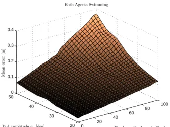
0 20 40 60 80 100 20 30 40 50 0 0.1 0.2 0.3 0.4 Head amplitude ahin % of ac Both Agents Swimming
Tail amplitude ac[deg]
M ea n er ro r [m ]
Fig. 5. Mean position estimation error, both agents swimming; average error: 0.13m, standard deviation: 0.0741m; at ah= 0deg, average error: 0.0465m, stan-dard deviation: 0.0159m.
relative to the active agent. Performance is measured using the mean position estimate error, over (no less than) eight oscillation periods of steady state. Results are shown in Figure 5. We observe that, the greater the oscillation am-plitude, the greater the impact on performance. However, the mean error along ah = 0deg remains small (average error of 4.65cm, for a distance of 110cm, i.e. 4.23% mean error). This illustrates the fact that, by placing electrodes on fore modules, and limiting the oscillation amplitude of the corresponding joints, we are able to mitigate the adverse effect of body undulations on sensing performance. The increase in error from ah= 0deg up to 20 or even 40% of a, is slow and close to linear. This linearity extends to a 100% for lower ac (roughly, for ac 6 30deg). For greater caudal amplitudes, the slope increases for greater percentages, particularly for ac> 40, ah> 60%.
To isolate the respective contribution of active and pas-sive agents’ body oscillations to the error, we repeat the above series of simulations, using identical center of mass trajectories, but enforcing zero body angles; i.e., the plat-forms have the same general movement, but are kept rigid (moving as if dragged by external means). We repeat this process with, in a first step, the active agent kept rigid while the passive agent swims, then consider the opposite scenario. In the case that only the passive agent is swim-ming, the error is only marginally reduced when compared to the previous case (down to an average error of 0.1046m from 0.13m, with standard deviation 0.0529m). In the case that the only the active agent is swimming, the error is dramatically reduced (down to an average 0.0576m, stan-dard deviation of 0.0159m). Deformations of the electric field induced by the active agent’s oscillations appear to have a relatively small impact on performance, compared to that of the passive agent’s. Finally, to evaluate to what extent one may generalize above findings to relative positions other than the lateral configuration considered so far, we select a particular swimming gait, and repeat the process for a range of relative bearings ρ and distances
d. In particular, we choose ac = 35deg, ah = 0deg, over
d∈ [1, 2], ρ ∈]−180, 180]. We obtain a rather homogeneous
error value, with an average below 0.09m and standard
deviation 0.04m. Homogeneity is broken by several peaks, at ρ = 0,±120, and 180deg, at which angles the algorithm appears to have (relative) blind spots, with error peaks at about 0.12m, 0.15m, and 0.18m, respectively.
4. THE ACTION-PERCEPTION TRADE-OFF Previous sections have shown that, within the range of gaits considered, the greater the amplitude, the greater the speed, but also the greater the perception error. Hence, in selecting a swimming gait, one should remain mindful of the gait’s impact on both speed and perception. In the following, we develop a simple cost function and use it to determine in what manner to adjust the gait, possibly in real time as mission requirements shift, and priorities between speed and perception are readjusted.
In designing this cost function, we build upon the speed and error surfaces in previous sections. For both quantities to be comparable, we normalize values. A wide range of such normalizations are possible. In particular, it may reflect respective importance afforded both aspects, possi-bly reflecting expected (or necessary) performance. More specifically, let the expected (or admissible) lowest speed be noted sl, while the maximum speed is sm. We adjust the surface in Figure 3 so that these two extreme values represent a speed cost of 1 and 0, respectively. Define
s(ac, ah) as the surface shown in Figure 3. Then, we may compute our speed cost js(ac, ah) as
js(ac, ah), 1 −
s(ac, ah)− sl
sm− sl
. (5) A sensible choice of parameters sl and sm could consist of the lower and upper speeds achievable within the gait range, leading to 06 js(ac, ah)6 1. If, however, the chosen limits strictly include the achievable range of speeds, the above inequality becomes strict. In our case, the average speed varies from (roughly) 0.2m/s up to 0.45m/s. We
use sl = 0.2m/s and sm = 0.45m/s. Similarly, noting
e(ac, ah) the perception error surface shown in Figure
5, and defining el and em as the lowest achieved and
maximum tolerable errors, respectively, we define the
perception cost as
jp(ac, ah),
e(ac, ah)− el
em− el
. (6)
Similar considerations hold regarding the choice of pa-rameters el and em. Hereafter, we select el = 0m and
em= 0.4m. Finally, we define βs, βp∈ [0, 1], βs+ βp= 1, to, respectively, represent the relative importance afforded to speed and perception. Our cost function assumes the following form,
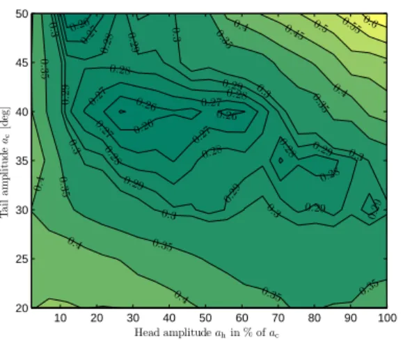
j(ac, ah), βsjs(ac, ah) + βpjp(ac, ah). (7) For illustration, assume we place slightly greater emphasis on perception than speed, using βs = 0.45, βp = 0.55. The iso-levels’ contours of the corresponding cost surface
j(ac, ah) are shown in Figure 6. We observe high cost
values along ac = 20deg and ah = 0deg (due to low
speeds), and for ac > 40deg and ah > 60% of ac. Conversely, there is a swath of lower cost values, starting from roughly ac ≃ 50deg, ah ≃ 15%, and crossing all the
0.26 0.27 0.28 0 .2 9 0.29 0.29 0.29 0.29 0.29 0.29 0 .3 0.3 0.3 0.3 0.3 0.3 0 .3 0 .3 5 0 .35 0.35 0.35 0.28 0.28 0.28 0.28 0.35 0.35 0.4 0.4 0.4 0.4 0.27 0.27 0.27 0.27 0.45 0.5 0.26 0.26 0.28 0.28 0.55 0.35 0.4 0.6 0.29 0.26 Head amplitude ahin % of ac T a il a m p li tu d e a c [d eg ] 10 20 30 40 50 60 70 80 90 100 20 25 30 35 40 45 50
Fig. 6. Iso-levels of j(ac, ah), with βs= 0.45, βp= 0.55. way to ac ≃ 30deg, ah ≃ 100%. This area of lower costs represents a range of acceptable trade-offs, for the specified relative importance of speed and perception.
5. CONCLUSION
The work presented addresses the integration of an electric sensing modality on an anguilliform swimming platform. Results illustrate the fact that adjusting the swimming gait to increase displacement speed tends to have a nega-tive impact on electric perception accuracy, and vice versa. Accordingly, in situations in which perception accuracy is of greater importance than speed, it proves beneficial to employ suboptimal, obviously slow swimming gaits. Comparable trade-offs between action and perception were observed in some species of electric fish, as discussed in MacIver et al. (2010). To account for both speed and perception when adjusting the gait, we propose the use of a simple cost function. Note that focus of the presented work was limited to a particular range of swimming gaits. Fur-ther investigations may be warranted, in particular con-sidering alternate η values. In addition, one may consider including heterogeneous swimming gaits within the group of swimmers, to exploit the fact that the active agent’s oscillations have a relatively small impact on perception accuracy. Accordingly, oscillation amplitude constraints on the active agent need not be as stringent as that placed on passive platforms. Implementation of the electric percep-tion modality on swimming robotic platforms is currently underway, both on AmphiBot, and on the ANGELS plat-form.
REFERENCES
ANGELS. ANGuilliform robots with Electric Sense.
http://www.theangelsproject.eu, 2012.
G. Baffet, F. Boyer, and P. B. Gossiaux. Biomimetic
localization using the electrolocation sense of the electric fish. In Proc. 2008 IEEE Int. Conf. on Robotics and
Biomimetics, Bangkok, Thailand, 2008.
P. K. Banerjee. The Boundary Element Methods in
Engineering. McGraw-Hill College, 1994.
D. N. Beal, F. S. Hover, M. S. Triantafyllou, J. C. Liao, and G. V. Lauder. Passive propulsion in vortex wakes.
Journ. of Fluid Mech., 549:385–402, 2006.
A. R. Blight. The muscular control of vertebrate swimming movements. Biological Reviews, 52:181–218, 1977.
C. Chevallereau, F. Boyer, V. Lebastard, and M. Be-nachenou. Electric sensor based control for underwater multi-agents navigation in formation. In Proc. 2012
IEEE Int. Conf. on Rob. and Aut., St. Paul, MN, 2012.
A. Crespi and A.J. Ijspeert. Amphibot II: An amphibious snake robot that crawls and swims using a central pattern generator. In Proc. 9th Int. Conf. on Climbing
and Walking Rob., pages 19–27, Brussels, Belgium, 2006.
A. J. Ijspeert. Central pattern generators for locomotion control in animals and robots: A review. Neural
Net-works, 21:642–653, 2008.
G. C. Kennedy and J. K. Holt. Developing a high efficiency means of propulsion for underwater vehicles. In Proc.
IEEE Southcon 1995, pages 352–356, Fort Lauderdale,
FL, 1995.
J. J. Leonard, A. A. Bennett, C. M. Smith, and H. J. S. Feder. Autonomous underwater vehicle navigation. MIT
Marine Laboratory Technical Memorandum 98-1, 1998.
M. J. Lighthill. Large-amplitude elongated-body theory of fish locomotion. Proc. of the Royal Society of London,
Series B, Biological Sciences, 179(1055):125–138, 1971.
M. A. MacIver, N. A. Patankar, and A. A. Shirgaonkar. Energy-information trade-offs between movement and sensing. PLoS Computational Biology, 6(5), 2010. E. J. Marey. Le Mouvement. Masson, Paris, 1894. K. A. McIsaac and J. P. Ostrowski. Motion planning for
anguilliform locomotion. IEEE Trans. on Robotics and
Automation, 19(4):637–652, 2003.
Y. Morel, M. Porez, and A. J. Ijspeert. Estimation of
relative position and coordination of mobile underwater robotic platforms through electric sensing. In Proc. 2012
IEEE Int. Conf. on Rob. and Aut., St. Paul, MN, 2012.
S. R. Noren, G. Biedenbach, J. V. Redfern, and E. F. Edwards. Hitching a ride: The formation locomotion strategy of dolphin calves. Functional Ecology, 22(2): 278–283, 2008.
M. Porez, A. J. Ijspeert, A. Crespi, J. Kn¨usel, and
F. Boyer. ANGELS: C.P.G.-based swimming controller for a single robot. Technical report, EPFL, ARMINES, 2009.
M. Porez, V. Lebastard, A. J. Ijspeert, and F. Boyer. Multi-physics model of an electric fish-like robot: Nu-merical aspects and application to obstacle avoidance. In Proc. 2011 IEEE/RSJ Int. Conf. on Intelligent
Robots and Systems, (to appear in), San Francisco, CA,
2011.
M. Sim and D. Kim. Electrolocation with an electric
organ discharge waveform for biomimetic application.
Adaptive Behavior, 19(3):172–186, 2011.
J. R. Solberg, K. M. Lynch, and M. A. McIver. Active electrolocation for underwater target localization. The
International Journal on Robotic Research, 27(5):529–
548, 2008.
M. S. Triantafyllou and G. S. Triantafyllou. An efficient swimming machine. Scientific American, 272(3):64–70, 1995.
B. Vanek, J. Bokor, and G. Balas. Theoretical aspects of high-speed supercavitation vehicle control. In Proc.
2006 IEEE Am. Contr. Conf., pages 5263–5268,
Min-neapolis, MN, 2006.
H. Weimerskirch, J. Martin, Y. Clerquin, P. Alexandre, and S. Jiraskova. Energy saving in flight formation.