HAL Id: hal-01018179
https://hal.archives-ouvertes.fr/hal-01018179
Submitted on 3 Jul 2014
HAL is a multi-disciplinary open access
archive for the deposit and dissemination of
sci-entific research documents, whether they are
pub-lished or not. The documents may come from
teaching and research institutions in France or
abroad, or from public or private research centers.
L’archive ouverte pluridisciplinaire HAL, est
destinée au dépôt et à la diffusion de documents
scientifiques de niveau recherche, publiés ou non,
émanant des établissements d’enseignement et de
recherche français ou étrangers, des laboratoires
publics ou privés.
Low Latency of Re-Authentication During Handover :
Re-Authentication Using a Signed Token in
Heterogeneous Wireless Access Networks
Hassane Aissaoui, Pascal Urien, Guy Pujolle
To cite this version:
Hassane Aissaoui, Pascal Urien, Guy Pujolle. Low Latency of Re-Authentication During Handover :
Re-Authentication Using a Signed Token in Heterogeneous Wireless Access Networks. 10th
Interna-tional Conference on Wireless Information Networks and Systems - WINSYS 2013, Jul 2013,
Reyk-javik, Iceland. pp.1-7. �hal-01018179�
Low Latency of Re-Authentication During Handover:
Re-Authentication Using a Signed Token in Heterogeneous Wireless Access
Networks
Hassane AISSAOUI
1, Pascal URIEN
1and Guy PUJOLLE
21
Network and Computer Science Department, TELECOM-ParisTech : LTCI CNRS Laboratory, rue Barrault, Paris, France
2
LIP6-University Pierre and Marie Curie Paris VI : CNRS Laboratory, 4 Place Jussieu, Paris, France {hassane.aissaoui, pascal.urien}@telecom-paristech.fr, [email protected]
Keywords: Wirless, Roaming, Handover, Digital Signature, Signed Token, Trusted Infrastructure, (Re)-authentication, (Re)-association, Mobility Anytime Anywhere, Ubiquitous Access, Low Latency, Real-Time Applications, AAA Framework, IEEE802.1x/EAP Protocol,
Abstract: Wireless networks provide several advantages over wired networks. They offer: a satisfactory bandwidth, mobility, easy deployment in difficult areas, long-term savings and the speed more and more higher. However, they also have some disadvantages in regard to security, performances during re-authentication, execution of real-time applications and interference from other electromagnetic sources (Bluetooth, microwave, etc.).
The existing solutions to reduce delays of Handover intercellular are specific solutions to a particular network or manufacturer of this technology.
The main objective of this paper is to propose novel mechanisms based on digital signatures to obtain low latency re-authentication during Handover in Wireless Access Networks. Our infrastructure will be based on trusted relationship between the heterogeneous access points and the authentication servers, in order to allow the mobility anytime anywhere to any user, and the ubiquitous access to the Future Internet, while ensuring the right level of security to both the end users as well to the wireless networks.
In this context, the main issues are to resolve the seamless Handover and the re-authentication during mobility of station. By using a signed token in our trusted infrastructure, we achieve a unique authentication and a fast re-authentication. Therefore, the requests to the authentication server are considerably limited.
1 INTRODUCTION
Unlike the Global System for Mobile Communications (GSM), the concepts of "Roaming and Handover" represent different actions.
In general, the process of handover is natively implemented in Mobile Station (MS), Base Station Controller (BSC) and Mobile Switching Center (MSC). The handover process in GSM involves four steps: the measurement, the request, the decision and the execution of handover. The request of the handover is generated by the BSC, and the decision is provided by the MSC. the other steps can be maintained by the BSC.
In wireless technologies, the Handover is a process that represents a mobility of the mobile node
(MN) to another target Point of Attachment (PoA), which offers a higher radio link quality.
The Handover is a fundamental mechanism in the inter-cellular communication; involving a set of operations that allows the mobile station to change the PoA without losing the connectivity and the session. These operations generate several steps and every single step causes delays and has an impact on the real-time applications such as Voice over IP (VoIP).
The rest of this paper is structured as follows: In (Section 2), we present an overview of the constraints and the causes of the inter-cellular delays and the impact of security on the Handover. In (Section 3), we examine proprietary solutions and improvements to the Wireless Local Area Networks (WLAN) or IEEE 802.11 Standards (WLAN 1997).
We will analyze, (Section 4), the WLAN Standards and Authentication, Authorization and Accounting Framework (AAA, 2000) which is based on Extensible Authentication Protocol (EAP 2004). In (Section 5), we illustrate the advantages and properties of digital signature that allow privacy and authenticity of a message, freshness against replay attacks / anti-replay, non-repudiation and anonymity (ISO 7498-2:1989). In (Section 6), we present our contribution which involves the use of asymmetric cryptography to sign tokens after client authentication, how this token save the context of a user session and how the stations perform a fast re-authentication during a Handover with this token?
Finally, we present in (Section 7), a conclusion and perspectives for future work.
2 INTERCELLULAR HANDOVER
PROBLEMS
2.1 Delays Due to Technology IEEE
802.1X Protocol
Delays due to Handover have been for a long time a recognized problem in wireless networks.
Certain experimental studies (Mishra et al., 2003) & (Velayos and Karlsson, 2004), attributed the delay in the IEEE 802.11 networks to the following phases: scanning, initialisation, re-association and re-authentication, during which a wireless station discovers neighboring access points.
According to (Zrelli and Shinoda, 2007), the use of EAP authentication causes significant delays regarding the re-authentication phase. Indeed, the EAP is a component of the AAA Framework to secure and control access to different networks.
In this centralized Framework, the delays due to the EAP protocol, during re-authentication phase of a mobile station can become a problem, especially in the use of real-time applications.
When the mobile station moves to a new AP, it loses its attributes and continuity of the session, and must re-authenticate again with the centralized Framework. This process of the re-authentication greatly increases latency during the Handover.
2.2 Constraint of Real-Time
Applications
VoIP is a real-time application, which imposes itself as the main application to test the validity of the performance of Handover in the wireless
network. Indeed, the main constraint of VoIP is the continuity of the flow so that there is no break in the conversation (da Conceicão et al., 2006), because human ear perceives a break of the voice greater than 50 ms during a VoIP communication.
3 OVERVIEW OF SOLUTIONS
THAT IMPROVE HANDOVER
In real-time applications, it is important to reduce the time of re-authentication and re-association during the Handover process while supporting advanced security mechanisms.
Table 1: Effect of roaming on Packet loss (Exact copy from a Source: Bangolae et al. 2006, p.6)
Authentication method Average Roaming time (ms) Average Packet Loss % Maximum Consecutive lost datagrams (Average) Baseline – Full 802.1x EAP Authentication 525 1.8 53 Fast Transition using 802.11r 42 0.2 6
Many enhancements have been made to the 802.11 standard (IEEE 802.11i), but it is not easily adaptable to the mobility of real-time applications (Bangolae et al., 2006). Implementing a caching mechanism in 802.11i has not improved the time roaming, it is around 350 milliseconds. This time of switching to a new AP is 7 times higher than the maximum latency for VoIP (which is about 50 ms).
In (Table 1), it shows the average time roaming (525 ms) and packet loss (1.8%) using basic authentication 802.11i, especially when there is a traffic load of the back-end (eg: Remote Authentication Dial In User Service) (RADIUS, 2000).
The first solution developed to reduce the latency in Handover is the Inter Access Point Protocol (IAPP). Based on IAPP, the Institute of Electrical and Electronics Engineers (IEEE) in 2003 led to the drafting of a "Trial-Use Recommended Practice" which presents the 802.11f (IAPP, 2003). The deployment of this recommendation has been virtually no communication. Despite this ratification,
the manufacturers have continued to methods of Roaming in their w technologies. It was abandoned in reasons, in particular the very latency.
4 IEEE 802.1X / EAP AN
FRAMEWORK
4.1 IEEE 802.1X
The Port Based Access Control protocol is developed by the IEE control ports (IEEE 802.1X, 2001) to a network after authentication wireless network. The main com mechanism are presented as followi
Supplicant: the system authenticated (station: STA).
Authentication Server (AS) user accounts (AAA Framework, Authenticator: network equi the role of mediator between th Point, Switch ...) and AS.
Each AP shares a secret with AS to perform mutual authentication secure channel.
Figure 1: 802.1X architecture of au The STA also shares a secre usually it is an username and passw is not authenticated, 802.1X does no to the network, only exchan authentication processes are relayed AP. Once the STA is authenticated the traffic related to this STA “Figur
to implement their wireless networks in 2006 for various slow Handover
AND AAA
rol or IEEE 802.1X EEE based on the 1). It allows access n from a wired or omponents of this wing: that will be S): that manages rk, RADIUS).uipment that plays the STA (Access
AS, to enable them on and establish a
f authentication. cret with the AS, ssword, as the STA not allow it access anges related to ed to the AS by the ted, the AP permits
ure 1”.
4.2 IEEE 802.1i and E
IEEE 802.1X is based on methods that are specified in th and respect the requirements 4017, in order to provide m between a station (STA) and There are two kinds of traffic EEAP over LAN (EAPoL (EAPoW): EAP is t specific frames between and Authenticator (AP). EAP over RADIUS (EA frames transported betw authentication server between both is a simple EAP packets without m of the package by the AP EAP is a transport protoco defines mechanisms for exch between devices. In order to wireless network infrastructur authenticated.
As shown in phase 0, "Figu of course, the association 802.1 which must be done pre authentication phase.
Figure 2: EAP Exc The authentication phase traffic (EAPoW):
Phase 1: (EAP-Reques request from the AP to the ST
EAP Protocol
on EAP authentication the RFC 3748 standard ts of the standard RFC mutual authentication and the local network. c EAP “Figure 1” : oL) or EAP over WLAN transported in these en the Supplicant (STA) EAPoRADIUS) : are the etween the AP and the (AS). The dialogue ple "re-encapsulation" of modifying the contents AP.col for authentication. It changing authentication to get the access to a ture, the STA must be
ure 2": the first step is, 2.11, of the STA to AP, previously at 802.1X
Exchanges.
se is then initiated via
uest.Identity) sending a STA.
Phase 2: (EAP-Response.Id response to the request, and a identifier (EAP-ID). This response to the RADIUS server via (EAP the request (Access.Request).
Phase 3: From this time, t begins exchanges that depend authentication method (EAP-TL EAP-MD5, LEAP, etc.). Therefor (requests and responses) are exc the RADIUS server and the STA authenticated, the AS and the S Master Key (MK). This MK is o session between the STA and the point plays only a passive relay at Phase 4: After successful au STA and the AS derive from the called "Master Session Key" (MSK the last messages sent by the A known only by the client and the s can be derived only by the client a
Phase 5: At the end of thes indicates to the AP the success o with EAP-Success message. transfers the MSK to the AP in th packet in the attribute "Microsoft RADIUS Attributes" (RFC 2548, 3078, 2001). This Attribute conta RECV-KEY), a session key Microsoft Point-to-Point Encry (MPPE). This key is intended packets received by the Authen remote STA. It is included in R Accept packets. From this momen no interaction and the exchanges c AP and STA. The AP takes dec control LAN instead of the server. Phase 6: The MSK is used a key, which is valid only for this the STA and the AP. This symm derived in three keys between the using the protocol "4-way handsh the Group Transcient Key (GTK stations connected to the same AP to secure the Multicast and Broad Service Set (BSS). It is renewe workstation disassociates from the Phase 7: All network traffic and the STA is encrypted.
Phase 8: When the STA is n the AS indicates to the AP the procedure with EAP-Failure messa
e.Identity) is STA attaching a first nse is retransmitted P Over Radius) in , the second stage d on the chosen TLS, EAP-TTLS, fore EAP messages exchanged between TA. If the STA is e STA negotiate a only valid for this the AS. The access at the moment. authentication, the he MK a secret key SK), during one of e AS. This key is e server. The MSK t and the AS.
ese exchanges AS s of this procedure . Then, the AS the Access.Accept oft Vendor-specific , 1999) and (RFC ntains for use by the cryption Protocol ed for encrypting enticator from the RADIUS-Access-ent, the server has s continue between ecisions on access er.
d as the symmetric is session between metric key will be he STA and the AP, shake". Especially, TK) shared by all AP. It is only used adcast in the Basic wed every time a the AP.
fic between the AP s not authenticated, the failure of this ssage.
5 DIGITAL SIGNAT
One of the main advant cryptography is that it offers th digital signatures. According signatures are used to ve properties: the authenticity o electronic message, but also t and non repudiation.
The digital signature (M Chapter 11) proves to the recip it has been signed by the a authentic and difficult to imita and is an integral part of the do
The Asymmetric Cryptogr asymmetric keys (public / pr mathematically related. An e decryption key are different; calculated from the other.
In general, one of the keys by everyone. This key will be encrypt a message. The o extremely difficult to find decrypted by the person who secret key called the private ke
Figure 3: Encryption and Decrypti Key.
The operation of asymm simple “Figure 3”: Bob encry public key of Alice. Alice can the associated key.
So it is possible to encryp with the public key, and only private key can decrypt it.
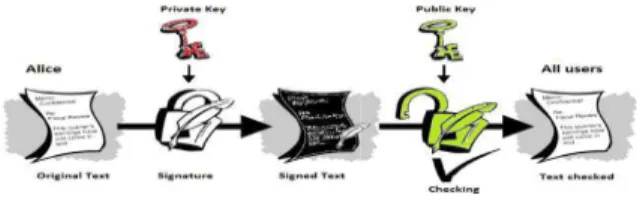
Figure 4: Digital S The digital signature is the public key encryption “Figure
ATURES
antages of asymmetric s the possibility of using g to ISO 7498-2, these verify the following of the author of an o to ensure its integrity
(Menezes et al., 2001, cipient of a message that e author, because it is itate. It is not reusable, document.
graphy consists of two private). The keys are encryption key and a nt; one key cannot be
eys is public and known be used by any person to original message is d as it can only be ho possesses the second key.
ption with an Asymmetric
mmetric encryption is crypts the text using the an decrypt the text with rypt a message securely nly the person with the
l Signature.
the opposite principle of 4”.
Alice encrypts a message with The result obtained can be decrypted the associated public key. This con has signed the content of this mess repudiate it and can be verified by a
When the document is volumi first hashed into just few lines. This a message digest. Then, the messag encrypted using the private key. T digital signature. This digital signa to the document and sent to the recip
First, the recipient decrypts the (using public key) and obtains the Then, the recipient hashes the rec into a new message digest. If th digests are the same, the recipient signed data has not been changed.
6 CONTRIBUTIONS
As mentioned above, in order to to a wireless network infrastructure be authenticated and must share with a PoA (an AP) “Figure 3”. T has no role and exchanges continue STA. The AP makes decisions on g the LAN.
Our approach consists to reuse between the STA and the AP authentication to ensure the continu of the STA.
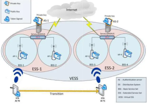
6.1 Principle of Virtual ES
At the beginning of wireles protocol exchanges between STA much simpler. The packet numbe connection, was mainly of four secure standards, the number of me considerably.Our contribution proposes e IEEE 802.11i standard, which allo switch faster and seamlessly from o target. The idea is based on the sign Asymmetric Cryptography to est infrastructure. This trusted infras considered as a wireless network the same ISP “Figure 5” and consist AS & AP.
In this large infrastructure of di we use multiple AS to simplify m ensure the scalability of the infrastru
ith her private key. ted by anyone with confirms that Alice essage. She cannot y a third party.
minous, it must be his process is called sage digest must be . The result is the nature is appended cipient.
he digital signature the message digest. received document the two message ent knows that the
to obtain an access ture, the STA must e the MSK secret . Therefore, the AS ue between AP and n granting access to se the MSK, shared AP, in each re-nuity of the session
ESS (VESS)
less network, the TA and AP were ber, to establish a r messages. With messages increased enhancements to allows a station to one AP to another igned token with an establish a trusted rastructure can be rk infrastructure of sists of one or more distributed access, y management andtructure.
Each AS handles APs or (BSS), which are deployed However, the public key is de We have restricted the deplo keys only to AS and APs.
The private key is used to each authentication of the ST saves the context of a user sess particular: "Time-Stamps" (to time), the message (EAP.Suc shared between the STA and th this token may also contain: profile, etc.
Figure 5: Virtual ESS I These APs are interconnec System (DS), usually is LAN interconnected. These differen via a DS in the same LAN (Extended Service Set). An ES ESSID.
The V.ESS is an extension the role of an approval auth infrastructure, one of the "AS" the private key and the AP public key.
In other words, when a ST AS-1 in BSS-1 “Figure 5”; th with attributes of the STA, negotiated as seen in (Section and this token is sent via AP-1
When the STA moves to A present the token. The AP authenticate the STA, because key of VESS infrastructure. token to retrieve all attributes, Once the MSK is recovered derived by AP-3 and STA a “Figure 2” Phase 6).
or a Basic Service Set d on the private key. deployed only on APs. loyment of asymmetric to sign the tokens after STA. The signed token ession and can contain in (to limit the token in uccess), and the MSK d the AP. For other uses, : STA attributes, user
Infrastructure.
nected by a Distribution N on which the APs are rent BSS interconnected AN are called an ESS ESS is identified by an ion of the ESS. It plays uthority. In this trusted S" signs the token with P decrypts it with the STA is authenticated by this AS-1 signs a token , including the MSK 4 “Figure 2” Phase 4), 1 to the STA.
o AP-3 in BSS-3, it will AP-3 will be able to se it possesses the public It then decrypts the , particularly the MSK. red, it can be reused and
Remark 1:
We notice that the AS-2 in DS-2 is not involved in this process of authentication because the re-authentication service has been delegated partially to the APs. This is to avoid the Back-End authentication, and to simplify considerably the number of authentication request between the Back-End and the STA.
6.2 Use case: (Re)-authentication
Process in VESS
We illustrate in “Figure 6” the authentication process and, during mobility, the re-authentication process of the STA in VESS infrastructure.
Figure 6: Virtual ESS: Approved Infrastructure. Scenario 1: STA authentication with AP-1 “Figure 6 (A)”
Phase 0: during this phase initialization and association, STA and AP-1 negotiate the EAP method with token signed.
Phase 1-2-3-4: authentication of STA and negotiation of the secret key (MSK). In these phases, nothing changes.
Phase 5: AS-1 signs the token containing (attributes, user profile, "Time-stamps", message EAP.Success and MSK) with the private key, and transmits to the AP-1 the token signed in Access.Accept : K-1 = is private key,
Access.Accept(EAP.Success+MSK+K-1{MSK…})
Then the AP-1 forwards the EAP.Success and signed token packet to the STA:
EAP.Success+K-1{MSK…}
Phase 6: the "4-way handshake" protocol, STA and AP-1 derived from the MSK, a bunch of keys used only in this session with AP-1.
Remark 2:
In this scenario, “Figure 6 (A)”, the exchanges between the STA, AP-1 and AS-1 are almost identical as in “Figure 2”. The only difference consists in signing a token after the authentication process of the STA. This signed token ensures continuity of service and the session of the STA.
Scenario 2: STA re-authentication with AP-3 “Figure 6 (B)”
In this scenario of mobility, the STA transits the AP-1 to AP-3. Phase 0: during this phase re-initialization and re-association, the STA and AP-3 negotiate the EAP method with token signed.
Phase 1-2: STA presents the signed token to the AP-3. The AP-3 decrypts it, using the public key: verifies the authenticity of the token and extract the MSK.
Phase 3: with the "4-way handshake" protocol, AP-3 and STA proceed to the derivation of other keys.
Phase 3: with the "4-way handshake" protocol, AP-3 and STA proceed to the derivation of keys, from the MSK.
The new derivated keyring is different from that obtained with AP-1. This keyring will be used only in this session with AP-3.
Remark 3:
In this scenario, the STA did not need to initiate a re-authentication process with AS-2, but it was meant only to present a signed token to the AP-3 to be authenticated. With this delegation of the re-authentication process to the AP-3, we avoided the invocation of the AS-2, so we reduced sufficiently the number of requests of EAP authentication; therefore, the Handover latency will be also low. The keys negotiation is done in four passes instantly and seamless.
6.1 Justification of our Approach
In comparison with other existing solutions (IEEE 80211f, 802.11r, etc.), our approach is very easy to implement, can use strong authentication (asymmetric or symmetric cryptography) and does not require many modifications of EAP authentication methods. The implementation of our EAP methods consists in modifying :The beacon at the time of the negotiation of the Robust Security Network Information Element (RSN IE) to notify the client 802.1x that wireless infrastructure supports the negotiation of the tokens signed.
The requests of (re)-association: the STA 802.11 must notify its choice of security policy by RSN IE included in these requests. The Access.Accept method to sign the token and transfer it to the STA and the AP.
7 CONCLUSION AND
PERSPECTIVES
This text describes the impact of security on the mobility and session continuity. We have identified the limitations of the EAP protocol in combination with the AAA Framework. This standard is used in the access control to different network technologies.
Several stages of the Handover process can be improved. In this paper, we proposed a fast Handover scheme; taking into consideration only delays in re-authentication during a transition in the same VESS.
To do this, we identified our needs in terms of security in relation to mobility. Thus we proposed to implement security components at the APs, to delegate the re-authentication service to APs in the VESS infrastructure.
In our scheme, the AAA Framework is ignored during the process of re-authentication. Therefore, we use a signed token that ensures trust in the VESS and manages mobility and continuity of the single session of STA. This proposition can solve the problem of intercellular delays (see Section II A).
In the next step, our main focus will be to resolve all technical barriers, evaluate the pertinence of our approach to meet the constraints of real-time applications. Finally, we propose improvements to the EAP protocol and we implement the new methods for managing virtual organizations with our signed tokens.
REFERENCES & STANDARDS
Bangolae, S., Bell, C. & Qi, E., 2006, ‘Performance study of fast BSS transition using IEEE 802.11r’, IWCMC '06 Proceedings of the 2006 international conference on Wireless communications and mobile computing pp. 737-742, 2006.
Da Conceicão, AF., Li, J., Florêncioy, DA., & Kon, F., 2006, ‘Is IEEE 802.11 ready for VoIP?’, Department of Computer Science, Institute of Mathematics and Statistics, University of Sào Paulo, Communication and Collaboration Systems, Microsoft Research. Menezes, AJ., Van Oorschot, PC., &Vanstone, SA., 2001,
‘Handbook of Applied Cryptography’, Chapter 11, CRC Press, Fifth Printing August 2001, freely available at <http://cacr.uwaterloo.ca/hac/>.
Mishra, A., Shin, M., & Arbaugh, W., 2003, ‘An empirical analysis of the IEEE 802.11 mac layer handoff process’ SIGCOMM Comput. Commun. Rev., vol. 33, no. 2, pp. 93–102, 2003.
Velayos, H., & Karlsson, G., 2004, ‘Techniques to reduce the IEEE 802.11b handoff time’ Tech. Rep., 20-24 June 2004.
Zrelli, S. & Shinoda, Y., 2007, ‘Experimental evaluation of EAP performance in roaming scenarios’, AINTEC '07 Proceedings of the 3rd Asian conference on Internet Engineering: Sustainable Internet, pp. 86-98, 2007.
AAA Authorization Framework, 2000, IETF RFC 2904, August 2000, <http://tools.ietf.org/html/rfc2904>. EAP, 2004, ‘Extensible Authentication Protocol’, IETF
RFC 3748, <http://tools.ietf.org/html/rfc3748>, Jun. 2004.
IAPP, 2003, IEEE std 802.11F-2003, ‘IEEE Trial-Use Recommended Practice for Multi Vendor Access Point Interoperability Via an Inter Access Point Protocol (IAPP) Across Distribution Systems Supporting IEEE 802.11 Operation’.
IEEE 802.1X, 2001, IEEE Std 802.1X, ‘Standards for Local and Metropolitan Area Networks: Port Based Access Control’, June 14, 2001.
ISO 7498-2, 1989, ‘Information processing systems -- Open Systems Interconnection--Basic Reference Model’ Part 2: Security Architecture.
RADIUS, 2000, ‘Remote Authentication Dial In User Service’, IETF Std RADIUS RFC 2865, June 2000, <http://tools.ietf.org/html/rfc2865>.
RFC 2548, 1999, IETF RFC 2548, March 1999, ‘Microsoft Vendor-Specific RADIUS Attributes’, <https://tools.ietf.org/html/rfc2548>.
RFC 3078, 2001, IETF RFC 3078, March 2001, ‘Microsoft Point-To-Point Encryption (MPPE) Protocol’, <http://www.ietf.org/rfc/rfc3078.txt>. WLAN, 1997, IEEE std 802.11, ‘WIRELESS LOCAL
AREA NETWORKS’, The Working Group for WLAN Standards, <http://www.ieee802.org/11/>.