HAL Id: hal-01317869
https://hal.inria.fr/hal-01317869
Submitted on 18 May 2016
HAL is a multi-disciplinary open access
archive for the deposit and dissemination of
sci-entific research documents, whether they are
pub-lished or not. The documents may come from
teaching and research institutions in France or
abroad, or from public or private research centers.
L’archive ouverte pluridisciplinaire HAL, est
destinée au dépôt et à la diffusion de documents
scientifiques de niveau recherche, publiés ou non,
émanant des établissements d’enseignement et de
recherche français ou étrangers, des laboratoires
publics ou privés.
Identifying knee prosthesis characteristics during swing
phase through optimization
Charles Pontonnier, Coralie Villa, Joseph Bascou
To cite this version:
Charles Pontonnier, Coralie Villa, Joseph Bascou. Identifying knee prosthesis characteristics during
swing phase through optimization. 22nd Congress of the European Society of Biomechanics, Jul 2016,
Lyon, France. �hal-01317869�
22nd Congress of the European Society of Biomechanics, July 10 - 13, 2016, Lyon, France
IDENTIFYING KNEE PROSTHESIS CHARACTERISTICS DURING SWING
PHASE THROUGH OPTIMIZATION
Charles Pontonnier (1,2,3), Coralie Villa (4), Joseph Bascou (4)
1. ENS Rennes, France; 2. Ecoles de Saint-Cyr Coëtquidan, France ; 3. IRISA/INRIA MimeTIC, France; 4. CERAH, France
Introduction
During gait, the swing phase is critical for above knee amputee people, as they cannot control their prosthetic shank and foot movement. The prosthetic knee kinematic and kinetic behavior are linked to its settings for swing phase such as stiffness and damping and its inertial characteristics [1], which can be optimized for a given gait velocity. This study presents a method to identify these settings and characteristics during swing phase using motion capture.
Methods
Model: A passive knee prosthesis during swing phase
was modeled as follows:
Figure 1: Planar shank equipped with a passive knee prosthesis and its model.
where 𝑚 was the shank and foot mass, 𝐼𝑐𝑐 their moment
of inertia and (𝑥𝐺, 𝑦𝐺) their center of mass position. The
knee joint was modeled using two mechanical characteristics that can be tuned on the prosthesis: the stiffness 𝑘𝑝 and the damping 𝜆𝑝.
The dynamics of such a system can be defined as: 𝑞̈ = 𝑓(𝑞, 𝑞̇, 𝑘𝑝, 𝜆𝑝, 𝑚, 𝐼𝑐𝑐, (𝑦𝑥𝐺𝐺)) (1)
with 𝑞, 𝑞̇, 𝑞̇ the joint angle velocity and acceleration.
Experimental data: Two configurations of knee
stiffness 𝑘𝑝 (𝑘𝑝 for setting 1 < 𝑘𝑝 for setting 2) of the
same knee / foot prosthesis were tested. The {shank+foot} inertia 𝐼𝑐𝑐𝑡𝑟was estimated using a trifilar
pendulum method [2]. Three motion trials were recorded for each configuration with an optoelectronic system (Vicon V8i, Oxford Metrics).
Each trial consisted in fixing the femoral part of the prosthesis, placing the shank part in a flexed position (𝑞 ≅ 90°), and letting it freely extend (𝑞 ≅ 0°) in a vertical plane, recording its movement(𝑞𝑒𝑥𝑝) .
Model 𝑚 (𝑘𝑔) 𝐼𝑐𝑐 𝑡𝑟(𝑘𝑔. 𝑚2) (𝑥𝐺 𝑦𝐺)(𝑚)
{Shank+Foot} 1.573 0.21 [0.25 -0.02]
Table 1: {Shank+Foot} estimated characteristics.
Identification: the knee 𝑘𝑝𝑜𝑝𝑡and 𝐼𝑐𝑐𝑜𝑝𝑡 characteristics
were computed using the experimental data and the
model, solving the following optimization problem using SQP algorithm [3]:
min𝐽 = ∑𝑛 (
𝑖=1 𝑞𝑒𝑥𝑝(𝑡𝑖) − 𝑞(𝑡𝑖))2, 𝑘𝑝 𝑎𝑛𝑑 𝐼𝑐𝑐 > 0 (2)
where 𝑘𝑝𝑜𝑝𝑡, 𝐼𝑐𝑐 𝑜𝑝𝑡 are the stiffness and inertia values that make experimental and simulation data fit best, 𝑛 the number of frames of the capture, 𝑞 the angle obtained integrating equation (1) using a 4th order
Runge-Kutta method and qexp the experimental angle.
Results
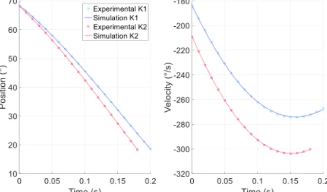
Experimental and simulation results showed good agreement (Figure 2) and the knee characteristics could be obtained (Table 2).
Figure 2: Experimental and simulation knee kinematics (angular position and velocity) for both stiffness settings.
Characteristics Setting 1 Setting 2
𝑘𝑝𝑜𝑝𝑡 (N. m/rad) 5.84±0.51 7.47±0.82 𝐼𝑐𝑐𝑜𝑝𝑡(kg.m²) 0.20±0.01 0.23±0.02
Table 2: Stiffness and inertia identification for both stiffness settings.
Discussion
The method properly estimated 𝐼𝑐𝑐 for both conditions
and logically estimated a higher 𝑘𝑝 for setting 2 than for
setting 1. Future studies will aim at identifying more parameters through optimization, potentially allowing improvement in prosthetic fitting.
References
1. Bonnet et al. CMBBE 12 S1:59-60, 2009
2. Harris and Crede, Shock And Vibration Handbook, BSG BOOKS, 1961