Poly(D,L-lactide) (PDLLA) foams with TiO2 nanoparticles and
PDLLA/TiO2-Bioglass® foam composites for tissue engineering scaffolds
ALDO R. BOCCACCINI, JONNY J. BLAKERDepartment of Materials and Centre for Tissue Engineering and Regenerative Medicine, Imperial College London, London SW7 2BP, UK E-mail: a.boccaccini@imperial.ac.uk
VÉRONIQUE MAQUET
Centre for Education and Research on Macromolecules, University of Liège, Sart-Tilman, B6, B-4000 Liège, Belgium WENDY CHUNG
Department of Materials and Centre for Tissue Engineering and Regenerative Medicine, Imperial College London, London SW7 2BP, UK ROBERT JÉÔME
Centre for Education and Research on Macromolecules, University of Liège, Sart-Tilman, B6, B-4000 Liège, Belgium SHOWAN N. NAZHAT
Division of Biomaterials and Tissue Engineering, Eastman Dental Institute, University College London, 256 Gray's Inn Road, London, WC1X 8LD, UK
Abstract
Porous poly(D,L-lactide) PDLLA foams containing 0, 5 and 20 wt% of TiO2 nanoparticles were fabricated and characterised. The addition of Bioglass® particles was also studied in a composite containing 5 wt% of Bioglass® particles and 20 wt% of TiO2 nanoparticles. The microstructure of the four different foam types was characterised using scanning electron microscopy (SEM) and their mechanical properties assessed by quasi-static compression testing. The in vitro behaviour of the foams was studied in simulated body fluid (SBF) at three different time points: 3, 21 and 28 days. The degradation of the samples was characterised quantitatively by measuring the water absorption and weight loss as a function of immersion time in SBF. The bioactivity of the foams was characterised by observing hydroxyapatite (HA) formation after 21 days of immersion in SBF using SEM and confirmed with X-ray diffraction (XRD) analysis. It was found that the amount of HA was dependent on the distribution of TiO2 nanoparticles and on the presence of Bioglass® in the foam samples.
1. Introduction
Tissue engineering has the aim to repair human tissue that has been aged, damaged or lost from injury, disease or infection so that its initial functions are restored [1]. This strategy should improve the quality or preserve the life of the patient through the delivery of biocompatible and/or living elements which become integrated into the body. Tissue engineering combines materials (scaffolds) and cells, and relies on the advancement in the engineering of innovative bioactive and biodegradable materials to make use of the body's natural repair mechanisms for amendment, and so induce the generation of new healthy tissues [2, 3].In general, materials for tissue engineering should encourage tissue regeneration by favourably reacting with surrounding living tissues when exposed to physiological fluids, a property referred to as 'bioactivity' [3].
In the most usual tissue engineering strategies, 3D porous engineered scaffolds made of biodegradable and biocompatible materials are used, which act as a template for cell adhesion, growth and proliferation for tissue formation [1-6]. The material type, morphology (microstructure), and mechanical properties required for scaffolds vary depending on the type of tissue it is intended to regenerate. For example, it is fundamental that the scaffolds used in bone tissue engineering have sufficient strength and stiffness to be able to provide the
mechanical support to withstand the stresses it is subjected to during the in vitro or in vivo bone regeneration process [4-7]. A range of synthetic biodegradable polymers, based on polylactic acid (PLA), polyglycolic acid (PGA) or co-polymers (e.g. PLGA) thereof, in numerous morphologies and architectures, have been developed and subjected to investigations regarding their suitability as tissue engineering scaffolds [8-12].
An advantage of using synthetic polymers is that the composition, microstructure and macrostructure can be controlled and hence the required properties of the scaffold can be acquired by design and materials choice. Scaffolds require a high porosity to provide a large volume for tissue infiltration, and to facilitate the nutriments
supply for cells and removal of waste products. Moreover these scaffolds must possess suitable pore architecture (pore size, surface area and interconnectivity) to enable cell migration, attachment and proliferation [4, 6-13].
Although increasing the porosity and pore size results in the rapid decrease in structural strength of the scaffold, this problem can be overcome by reinforcing the polymer matrix with stiff inorganic particles, i.e. developing a composites approach [13]. Different bioactive ceramics such as calcium phosphates, hydroxyapatite (HA) powders and bioactive glass fibres and particles have been used as reinforcing phases in such highly porous biocomposites, mainly for bone-tissue engineering applications [6, 13-18]but also recently for soft-tissue engineering [19, 20]. Previous research has shown that on addition of bioactive glass (e.g. 45S5 Bioglass®) particles to polymer scaffolds (e.g. PDLLA), improved mechanical properties such as higher compressive strength and modulus, hardness, and a decrease in damping might be achieved [13, 14, 20]. Bioglass® has a rapid biochemical response in physiological fluids ('bioactivity' [21]) and due to improving mechanical
properties in PDLLA or PLGA based composites, it has been shown to be the filler of choice for optimising such porous scaffolds to promote tissue growth in bone repair. Generally, the rate of scaffold bioactivity can be controlled by the amount of bioactive glass incorporated in the polymer matrix [13-19]. When exposed to physiological fluids the glass reacts to form tenacious bonds to both hard and soft tissues though cellular activity, thus demonstrating the bioactivity of this material [21]. Moreover, recent research has confirmed a "gene regulating effect" of the dissolution products of Bioglass® [22].
Apart from bioactive glasses and, HA conventional bioinert ceramic particles, such as titania (TiO2) and alumina (Al2O3), which have been shown to have exceptional biocompatibility properties with bone cells and tissue, have not been considered so far for combination with biodegradable polymers for applications in bone tissue
engineering scaffolds. In the case of conventional Al2O3 and TiO2, this is predominantly due to a lack of bone bonding or insufficient osseointegration [21]. However, on reducing the particles to nano-sizes (of less than 100 nm) both Al2O3 and TiO2 possess significantly different properties from those of the same material in the bulk or micrometer-size particulate form [23-29]. Extensive research results by Webster and co-workers [23-27]give evidence that polymer matrix composites containing nano-sized titania particulate inclusions compared to micrometer-sized titania particles exhibit enhanced adhesion of osteoblasts, and propensity to increased deposition of calcium-containing minerals [26]as well as a decreased adhesion of fibroblasts [23-27]. There is further evidence in the literature that enhanced cell behaviour can be achieved with composites that contain nano-ceramic particulate inclusions [28, 29]. So far research on biocomposites containing ceramic nanoparticles has been conducted on 2D films, and there is no extensive record of previous work known to the authors pertaining to the development of 3D biocompatible porous structures relevant for tissue engineering scaffolds based on biodegradable polymers containing ceramic nanoparticles.
In the present contribution we have developed 3D poly (D,L-lactide) (PDLLA) foams containing TiO2 nanopar-ticulate additions and in one case also incorporating Bioglass® particles. These novel composites, designed as scaffolds for bone tissue engineering, were characterised in terms of their morphology, compressive mechanical properties as well as in-vitro degradation and bioactive behaviour in simulated body fluid.
2. Experimental
2.1. Materials
Poly(D,L-lactide) (PDLLA) was the polymer chosen for the fabrication of foams, following our previous related research [30]. PDLLA (Purasorb®) with inherent viscosity of 0.39 dl/g was obtained from Purac Biochem (Goerinchem, The Netherlands) and used without further purification. Dimethylcarbonate (DMC, of >99% purity) was purchased from Sigma Aldrich. Commercially available TiO2 nanoparticles (Degussa AG, Frankfurt, Germany) were used as filler. Manufacturer's data indicate that the average particle size is 21 nm and their crystalline structure is a combination of anatase (70 wt.%) and rutile (30 wt.%). The bioactive phase
incorporated as filler in one of the composite foams was 45S5 Bioglass® [21]; a melt-derived bioactive glass powder of mean particle size <5 µm. The chemical composition of the glass (in percentage of weight) is as follows: SiO2,45; CaO, 24.5; P2O5, 6; NaO2, 24.5 [21].
2.2. Foam fabrication
Neat PDLLA, PDLLA/Ti02 and PDLLA/TiO2/ Bioglass®-filled composite foams were prepared by thermally induced phase separation (TIPS) and subsequent solvent sublimation, which is a technique described in detail elsewhere [13]. In brief, PDLLA was dissolved in DMC at a polymer weight to solvent volume ratio of 5% (w/v). The mixture was stirred overnight to obtain a homogeneous polymer solution. Given quantities of Bioglass® particles and TiO2 nanoparticles as appropriate were added to the polymer solution, which was then
transferred to a lyophilisation flask and sonicated for 15 min to achieve a homogenous distribution of inclusion particles. The flask was subsequently immersed in liquid nitrogen and maintained at -196°C for 2 h. The frozen mixture was then placed under vacuum (10-2 Torr) and transferred to an ethylene glycol bath, which was maintained at -10°C. The solvent was sublimed at this temperature for 48 h and then at 0°C for 48 h. Finally, the sample was completely dried at room temperature in a vacuum oven until reaching constant weight. Four different compositions of foams were investigated, as shown in Table I.
Cubic samples (5 x 5 x 5 mm3) were cut using sharp razor blades from TIPS produced monoliths (~100 mm diameter). A variation in through-thickness pore architecture was observed on cutting the monoliths. Distinct layers were seen: a thin (~3 µm), dense layer at the top surface, preceded by a more ordered region of 1-2 mm thickness and then a well ordered and homogeneous region, followed by a further dense layer (~10 µm in thickness) at the bottom of the foams. Care was taken to ensure the cut samples were representative of the homogeneous section of the monolith. Forty samples of each of the four foam types were cut out so that enough samples could be tested for the different time periods of immersion in simulated body fluid (as discussed below), and for mechanical property determination using quasi-static compression tests.
TABLE I : Foam compositions investigated
TiO2 (wt%) Bioglass® (wt%) Neat PDLLA - - PDLLA/TiO2 5 - PDLLA/TiO2 20 - PDLLA/TiO2/Bioglass® 20 5 2.3. Microstructural characterisation
Scanning electron microscopy (SEM) was used to investigate, in detail, the change in microstructure and pore arrangement, as well as the distribution of TiO2 and Bioglass® particles in different regions within samples. Representative through-thickness sections were obtained from the monolithic disks of each composition. Axial and transverse sections were investigated. Steps were carefully cut (using a razor blade) into the samples to enable the observation of the aforementioned variation in through-thickness pore architecture. Samples were gold coated for 120 s under a current of 20 mA before examination under an accelerating voltage of 20 kV using a JEOL 5610 LV SEM (JEOL Ltd, Japan).
2.4. Quasi-static compression testing
Quasi-static compression tests were conducted using a Pyris run DMA7e (Perkin-Elmer Instruments) in the static stress scan mode. Cubic specimens with dimensions of 5x5x5mm3 cut from the most homogenous region of the foams were tested to failure. Care was taken to ensure the load was applied in the direction of the tubular macropores. The specimen size was chosen as buckling and skewing of the sample became a problem at smaller cross section to height ratios and this particular size was selected to allow comparison to previous results on TIPS produced foams [13]. The height of the foams was determined by the probe position following the application of an initial static stress of 2 kPa. Tests were conducted on five repeat specimens of each composition at room temperature to a maximum stress of 300 kPa, at a stress rate of 20 kPa per minute. The compressive modulus, compressive yield stress and strain were evaluated from the stress-strain and modulus-strain responses.
2.5. In vitro degradation studies
The technique used to prepare simulated body fluid (SBF) was the same used in previous studies [6, 30], and followed the method introduced by Kokubo et al. [31]. The solution was magnetically stirred and buffered to a pH of 7.25. Briefly, 30 samples of each composition were placed into 100 ml conical flasks (one flask per composition, 10 samples per flask). Flasks containing the specimens in SBF solution were sealed and placed for up to 28 days in an orbital shaker (New Brunswick Scientific, C24 Incubator Shaker), which maintained a temperature of 37°C and rotated at 175 rpm. The SBF was changed every 3 days to prevent cation concentration. After each time point of interest (3, 21 and 28 days), 10 samples were taken out from each flask and dried in a vacuum dessicator. Measurements of the SBF pH for each sample type were taken at the time of sample extraction or on replacing the SBF.
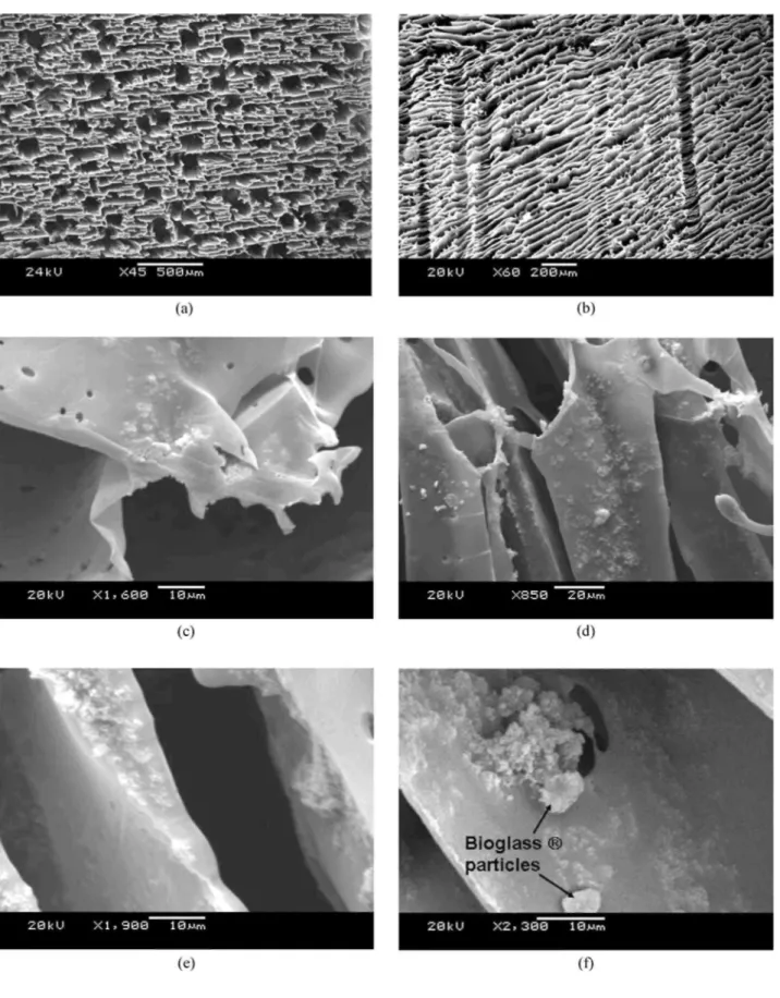
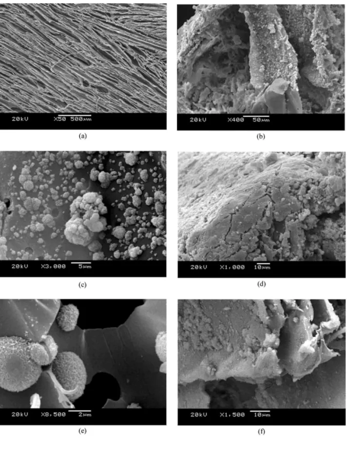
Figure 1 : SEM micrographs of (a) transversal and (b) longitudinal cross sections of neat PDLLA foams. TiO2
nanoparticle dispersion in foams containing (c) 5 wt% TiO2, (d) and (e) 20 wt% TiO2 at different magnifications
The amount of water absorbed and weight lost by the foams was recorded following immersion in SBF after the relevant time periods (3, 21 and 28 days). At each time point a sample of each foam composition was removed, and the excess water (on the surface) was absorbed using blotting paper, and subsequently the 'wet' weight was measured. These samples were then dried in a vacuum dessicator and the 'dry' weight recorded.
To confirm HA formation on the relevant foams, SEM and X-ray diffraction (XRD) analysis were conducted on the foams after different immersion times in SBF. Samples were cut to permit analysis of the foam interior. Changes in the micro structure of the foams and the formation of HA on both axial and transverse cross sections of foams were investigated by detailed observation of SEM images.
3. Results and discussion
3.1. Microstructure of as received samples
SEM images of typical PDLLA foams with and without TiO2 particulate additions prepared in this study are presented in Fig. 1a-e. Fig. 1ashows the porous structure in transversal cross-section at the middle of the sample demonstrating a well ordered pore arrangement within this region of the foams. The anisotropic nature of these foams is demonstrated in Fig. 1b, which shows the micro structure in the longitudinal cross-section. The structure consists of well defined tubular macropores of ~100 µm diameter, interconnected by micropores of ~10-50 µm diameter. The structure was generally very similar for all foam types, which also conforms to the pore architectures seen in previous studies on TIPS-produced scaffolds of PDLLA and PLGA [13, 32]. For foam samples containing 5 wt% TiO2, some particle agglomerations were observed on the surfaces of the pore walls. Fig. lcshows, for example, some agglomeration near the top of a sample containing 5 wt% TiO2, however the agglomeration effect was more pronounced in samples filled with 20 wt% titania. More TiO2 was observed around regions near the top of the as-fabricated foams, in comparison to the centre. In order to investigate the internal structure of the foams, these were cut with a razor blade and the surfaces examined by SEM. A relatively homogeneous nano-particle distribution was observed through the thickness of the foams, a typical micrograph showing a section of the foam thickness is shown in Fig. 1dfor a 20 wt% TiO2 containing foam. Fig. 1eshows a dispersed distribution of TiO2 particles on the pore walls at high magnification. A homogeneous distribution of TiO2 particles embedded in the pore walls is seen in the middle of the foam, thereby endowing the scaffolds with a nano-scale surface roughness. A nano-structured surface should potentially provide enhanced osteoblast cell adhesion, as suggested in the literature for TiO2 nano-particulate/PLGA films and other nano-structured composites [23-29].
For samples containing 20 wt% TiO2 and 5 wt% Bioglass®, the TiO2 particles (or clusters of them) were seen to be well distributed throughout the foam samples. Fig. 1fdepicts the typical micro structure of a
PDLLA/TiO2/Bioglass® foam, showing qualitatively a fairly homogeneous distribution of both particle types in the pore walls, with discrete Bioglass® particles of approximately 5 µ m in size and evidence of some nano-particulate titania agglomeration.
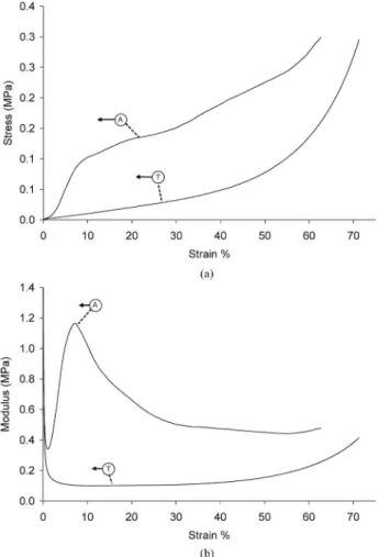
Figure 2 : Typical trends of stress-strain (a) and modulus-strain (b) in both the longitudinal (axial) (A) and transverse directions (T) with respect to the direction of macropores for a PDLLA foam containing 20 wt% TiO2.
3.2. Mechanical characterisation
Compressive mechanical tests were conducted in the direction parallel and perpendicular with respect to the tubular macropores. The stress-strain response observed agreed well with characteristic behaviour reported in the literature for foam systems [33, 34], as shown in Fig. 2. This behaviour consisted of three distinct regions: an initial Hookean region in which stress increased in proportion to strain due to compression of the cell elements, a plateau region representing plastic collapse and buckling of the cell elements, and a final region where the stress increased rapidly with strain due to effective densification of the foam structure.
Accordingly, the materials showed an increase in modulus in response to strain, which peaked at a certain value and then decreased prior to subsequent strain increase. For comparison, tests were also conducted with the load applied perpendicularly to the direction of the macropores. This transverse mechanical behaviour in
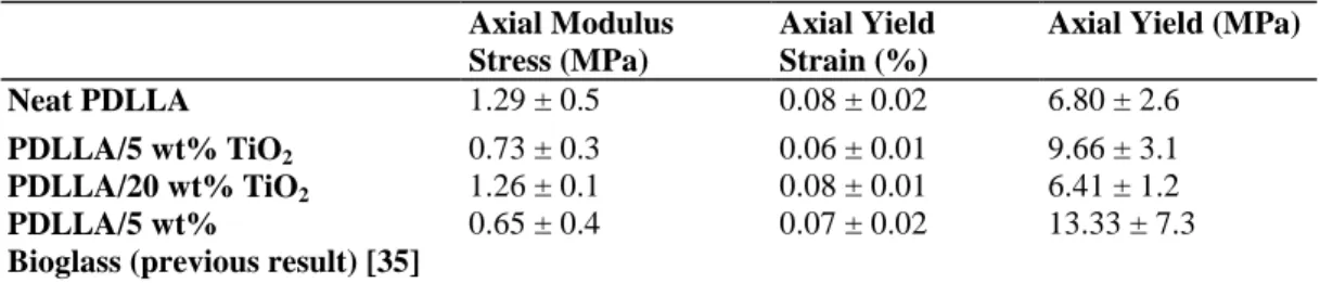
compression, also shown in Fig. 2, displayed a markedly different response to that of the longitudinal loading. There appeared to be no obvious micro-failure response due to buckling of the tubular macro-pores, indeed the behaviour of all foams was dominated by the effect of densification of the foams. Testing in both directions demonstrated thus the mechanical anisotropy of the foams which is in agreement with recent work conducted on Bioglass®-filled PDLLA foams [35]. Young's modulus, compressive yield stress and strain were evaluated from the determined stress-strain and modulus-strain responses and are shown in Table IIfor the foam systems investigated in longitudinal direction. The compressive Young's modulus was determined from the maximal value in the modulus-strain response. Although there is an apparent trend towards a reduced maximum modulus regarding the PDLLA with 5 wt% titania compared to the neat PDLLA, this result is not significant given the large data scatter. Such deviations in the results are likely due to variations in the pore structure between the monolithic samples. Previous work has shown that there is only moderate increase in modulus for these highly porous TIPS produced foams with Bioglass® particulate inclusions [35]. Moreover, it has also been shown that filling these foams with high volume fractions of inclusions can result in alteration to the pore architecture, evidenced by variation of total porosity and an increase in pore wall rugosity [13]. This porosity change should
affect also the effective Young's modulus of the present composites, the quantification of this effect was, however, beyond the scope of this study.
TABLE II: Quasi-static compression properties of the foams
Axial Modulus Stress (MPa)
Axial Yield Strain (%)
Axial Yield (MPa)
Neat PDLLA 1.29 ± 0.5 0.08 ± 0.02 6.80 ± 2.6
PDLLA/5 wt% TiO2 0.73 ± 0.3 0.06 ± 0.01 9.66 ± 3.1
PDLLA/20 wt% TiO2 1.26 ± 0.1 0.08 ± 0.01 6.41 ± 1.2
PDLLA/5 wt%
Bioglass (previous result) [35]
0.65 ± 0.4 0.07 ± 0.02 13.33 ± 7.3
3.3. In vitro study of bioactivity
The possible bioactive behaviour of the foams was assessed by immersion in SBF for different periods of time, as is common practice in the study of biomaterials for bone tissue engineering [6, 30]. SEM micrographs were taken from samples after 3 and 21 days of immersion in SBF and the formation of HA was investigated. After 3 days no HA growth was observed on the surface of any of the samples, and no other microstructural change of the foams was observed. However, significant changes were observed after 21 days of immersion in SBF. In general pore sizes were found to shrink to roughly the same dimensions for all foam compositions. Fig. 3ashows the transversal cross-section of a neat PDLLA foam after 21 days of immersion in SBF. It can be seen that the sizes of the pores appear reduced in comparison with the as-fabricated material (compare with Fig. 1a). The walls are seen to be more compacted, thereby causing a densification effect. This observation has also been reported in previous studies on similar foams [30].
HA formation on the surface of foams containing 5 wt% TiO2 was observed after 21 days of immersion in SBF, in particular a large amount of HA crystals was observed on pore walls near the top surface, as shown in Fig.3b.
HA formation was observed to a depth of approximately 300 microns into the material from the top surface, therefore, leaving a few regions inside the foam with negligible HA formation. Titania nanoparticles were observed on the foam walls where no HA growth had occurred. Typical ranges of HA crystal sizes in a sample with 5 wt% TiO2 are observed in Fig. 3c, some crystals were less than 1 micron and others 3 to 4 microns in size. Crystalline HA layers rather than individual crystals were formed on foams containing 20 wt% TiO2 upon immersion in SBF for 21 days. Fig. 3dshows an SEM image taken at high magnification depicting a typical HA crystalline layer on the foam surface. The thick layer is probably formed due to the large agglomerations of titania particles in these foams (Fig. 1d), which may act as sites for the nucleation and growth of HA. Regions inside the foams without HA were observed where individual titania particles were present. The formation of these thick HA layers may result in the pores being blocked, thereby impeding the penetration of SBF fluid into the porous interior of the foam. Fig. 3eshows the HA crystals on these pore walls at high magnification. HA layers were also observed on the foam sample containing both TiO2 and Bioglass®. HA was observed to grow homogeneously inside the samples on pore walls, as seen in Fig. 3f. Therefore a more uniform growth of HA crystals within the porous material occurred in this foam system, which is attributed to the presence of the intrinsically bioactive Bioglass® particles. Previous work on PDLLA/Bioglass composite foams with
concentrations of Bioglass® of 5 wt% and 40 wt% has conclusively proved the bioactivity of such composites [30].
Samples that were used for water absorption tests after 21 days immersion in SBF (discussed in the next section) were also characterised using XRD analysis. The analyses were carried out on inner surfaces of the samples.
Figure 3: SEM micrographs showing the microstructure of foams after 21 days of immersion in SBF. (a) Low magnification image of a pure PDLLA foam. HA formation near the upper surface of samples containing 5 wt% TiO2 at (b) low and (c) high magnification. A thick HA layer on a sample containing 20 wt% TiO2 is shown in
(d), while HA crystals on a sample containing 20 wt% TiO2 are seen on the high magnification image in (e). HA
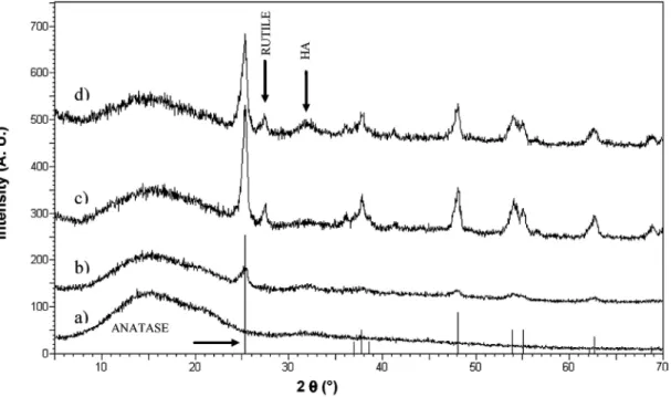
Figure 4 : XRD patterns showing diffraction peaks for the different samples after 21 days of immersion in SBF: (a) Pure PDLLA foam; (b) PDLLA containing 5 wt% TiO2; (c) PDLLA containing 20 wt% TiO2; (d) PDLLA
containing 20 wt% TiO2 and Bioglass®.
Fig. 4compares the diffraction patterns for each of the four foam types. The figure shows the distinct peaks of the titania modifications anatase and rutile present in all composite samples. Moreover, there was evidence of the crystalline peak of HA in samples with 20 wt% TiO2 and those containing both TiO2 and Bioglass®. It is known that the titania nanoparticles used were essentially 70% anatase and 30% rutile. The large peak at 2Θ = 25° is characteristic of the structure of anatase, which correlates with the greater percent of anatase in the starting TiO2 powder. For the foam sample containing 5 wt% TiO2 very small peaks (shown in Fig. 4) are observed. The area under the titania peaks are higher for samples containing 20 wt% titania compared with samples containing 20 wt% titania and 5 wt% Bioglass®. The general ill-defined HA peaks may be due to HA being weakly crystalline or at the beginning of its crystallisation. The crystallinity of the HA formed upon immersion times in SBF should increase for longer immersion times, as also confirmed in previous studies [6, 30].
3.4. In vitro degradation
Fig. 5ashows the pH variation of the SBF solution containing each foam type at the time points investigated. The pH fluctuations observed in the 28 day period were relatively small, where the values ranged between 6.91 and 7.47. The pH of the media surrounding the particulate-filled foams tended to increase during the initial degradation period (3 days). This pH increase for samples containing TiO2 can be explained by the absorption of water and formation of titanium hydroxide, Ti-OH groups. The pH increase was greatest for SBF in contact with samples containing Bioglass®, where a pH of 7.47 was recorded after 3 days; this is due to the dissolution of alkaline ions from the glass particles and formation of Si-OH groups. For pure PDLLA foams, the pH dropped on breaking down of the polymer by chain-scission and increasing numbers of carboxylic end-groups. The SBF solution in contact with samples containing 20 wt% titania and 20 wt% titania with 5 wt% Bioglass® exhibited a drop in pH between the 10th and 17th day. The pH of the SBF containing the PDLLA foams with 5 wt% titania dropped later, between the 17th and 20th day of immersion. The maximum pH drop for all the samples was observed after 21 days of immersion where values decreased to about 7.02 on average.
Figure 5: Graph showing the changes in pH of SBF versus immersion time of different samples: neat PDLLA (x); PDLLA containing 5 wt% TiO2 (□); PDLLA containing 20 wt% TiO2 (∆); PDLLA containing 20 wt% TiO2
and Bioglass® (•).
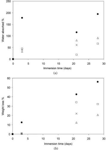
Figure 6: Amount of (a) water absorption and (b) weight loss as a function of immersion time in SBF for the different foam types: neat PDLLA (x); PDLLA containing 5 wt% TiO2 (□); PDLLA containing 20 wt% TiO2 (∆);
PDLLA containing 20 wt% TiO2 and Bioglass® (•).
In general, the pH of the incubation fluid is expected to drop as it becomes more acidic due to scission of polymer chains. With addition of Bioglass® particles, the degradation of samples is expected to slow down, due to the local buffering effect of the alkali in the glass [13]. This effect may have been observed if longer time periods of immersion had been studied. The behaviour of the pH of the incubation solution for samples containing Bioglass® particles can be compared to experiments previously undertaken [32], where pH changes were studied when PDLLA foams with varying volume fractions of Bioglass® were incubated in phosphate
buffer saline (PBS) solution. In those experiments the pH values of the pure PDLLA and PDLLA foams containing 5 wt% Bioglass® decreased; those containing higher percentages (i.e. 10 and 40 wt%) initially demonstrated increasing pH values, which later decreased after 10 days.
In general, the longer the samples were immersed in SBF the more water they absorbed. Fig. 6ashows the amount of water absorption as a percentage weight increase for each sample type at 3, 21 and 28 days of immersion in SBF. At 3 days the amount of water absorption for each sample was similar and fairly low, except for the sample containing Bioglass®, which absorbed 3 times the amount of the other samples. This
titania/Bioglass® containing sample absorbed more water at each of the time points than any other sample, showing up to 195 wt% increase after 28 days of immersion. Samples containing 5 wt% TiO2 exhibited the lowest amount of water absorption after 21 and 28 days of immersion. Fig. 6bshows values for weight loss of each sample type at each time point in SBF. There was a very small change in weight loss after 3 days
immersion for all samples, with the exception of the Bioglass® containing foam, which showed a considerably larger weight loss. Greater weight losses were recorded concomitant with increased time of immersion, and at the same time the variability of results increased. Weight loss for each time period was noticeably largest for samples containing Biolgass®. Moreover the foam sample with 5 wt% titania had a larger weight loss than the pure PDLLA foam. From a macroscopic point of view degradation did not occur equally on each surface of the foams, as irregular shaped foams were observed after being immersed in SBF. Qualitatively assessed by visual inspection, degradation occurred initially at the edges and it then proceeded into the centre from the sides of the samples. In samples containing 5 wt% titania, the originally cubic foams degraded down to thin samples of about 1 x 4 x 4 mm3 after 28 days incubation in SBF. When HA crystals on the surfaces of 20 wt% titania samples formed (as shown in Fig. 2d and e), they blocked pores and so the rate of weight loss was reduced. A further quantitative study on the degradation of PDLLA/TiO2 foams should be conducted using size exclusion chromatography (SEC) analysis of polymer chains. Nevertheless the present results demonstrate a complex effect of the presence of TiO2 nano-particles and concomitant formation of HA on degradation of PDLLA foams.
4. Conclusions
PDLLA foams containing TiO2 nanoparticles and Bioglass® (45S5) particles were fabricated by TIPS process for applications in tissue engineering scaffolds. The porous structure was characterised by SEM. Bioactivity and degradation of samples were investigated by immersion in SBF for up to 28 days. In the case of the pure PDLLA foams, negligible HA formation was evidenced by SEM and XRD analyses following immersion in SBF. When TiO2 nanoparticles and/or Bioglass® particles were incorporated, HA growth on the foam surfaces was observed after 21 days of immersion in SBF. The water absorption and weight loss results showed significant changes after 21 days in SBF, whereby the foams begun to shrink and became more rigid. The increased rigidity can be explained by the HA growth and by the fact that both pore size and pore volume decrease (effective densification of the foam) with increasing time in SBF. The large agglomerations of titania on the top surfaces of samples containing 20 wt% titania promoted the formation of a thick layer of crystalline HA. This thick HA layer caused the rate of weight loss to decrease and so degradation rate was delayed. An optimum composition of titania may lie between 5 and 20 wt% to prevent such a thick HA layer from forming and so to allow more in-growth of HA through the 3D pore network of the foam. Samples containing 5 wt% Bioglass® exhibited the greatest weight loss and water absorption and a more even formation of HA throughout the 3D pore structure of the foams. The results thus demonstrated that TiO2 nanoparticles and Bioglass® particles may be both considered, in tailored concentrations, to be adequate fillers for PDLLA based foams for tissue engineering scaffolds.
Acknowledgements
JJB acknowledges the UK Engineering and Physical Science Research Council (EPSRC), London, for his studentship. SNN is grateful to the UK EPSRC for financial support. CERM is indebted to the "Politique Scientifique Fédérale" in the frame of the "Pôles d'Attraction Interuniversitaires (5/03): Chimie et Catalyse Supramoléculaire", for financial support.
References
1. D. WILLIAMS, Materials Today 7 (2004) 24.
2. K. J. L. BURG, S.PORTER and J. F. KELLAM, Biomaterials 20 (2000) 2347. 3. L. L. HENCH and J. M. POLAK, Science 295 (2002) 1014.
5. R. LANGER and J. VACANTI, Science 260 (1993) 920.
6. J. A. ROETHER, A. R. BOCCACCINI, L. L. HENCH, V. MAQUET, S. GAUTIER and R. JEROME, Biomaterials 23 (2002) 3871. 7. J. R. JONES and L. L. HENCH, Mat. Sci. Technol. 17(2001)891.
8. L. WU and J. DING, Biomaterials 25 (2004) 5821.
9. P. X. MA and R. ZHANG, J.Biomed. Mater Res. 56 (2001) 469. 10. R. Y. ZHANG and P. X. MA, J. Biomed. Mater. Res. 44 (1999) 446.
11. A. S. P. LIN, T. H. BARROWS, S. H. CARTMELL and R. E. GULDBERG, Biomaterials 24 (2003) 481. 12. L. D. HARRIS, B. S. KIM and D. J. MOONEY, J. Biomed Mater. Res. 42 (1998) 396.
13. A. R. BOCCACCINI and V. MAQUET, Comp. Sci. Technol. 62 (2003) 2417.
14. K. ZHANG, Y. WANG, M. A. HILLMYER and L. F. FRANCIS Biomaterials 25 (2004) 2489. 15. R. C. THOMSON, M. J. YASZEMSKI, J. M. POWERS and A. G. MIKOS, Biomaterials 19(1998) 1935. 16. J. M. TABOAS, R. D. MADDOX, P. H . KREBSACH and S . J. HOLL1STER, Biomaterials 24 (2003) 181. 17. H. H. LU, S. F. EL-AMIN, K. D. SCOTT and C. T. LAU-RENCIN, J. Biomed. Mater. Res. 64 (2003) 465. 18. A. A. IGNATIUS, S. WOLF, P. AUGAT and L. E. CLAES J. Biomed. Mater. Res. 57 (2001) 126.
19. S. VERRIER, J. J. BLAKER, V. MAQUET, L. L. HENCH and A. R. BOCCACCINI, Biomaterials 25 (2004) 3013. 20. A. R. BOCCACCINI, J. J. BLAKER, V. MAQUET, R. M . DAY and R. JEROME, Mater Sci. Eng. C 25 (2005) 23. 21. L. L. HENCH, J. Am. Ceram. Soc. 81 (1998) 1705.
22. L. L. HENCH, I. D. XYNOS and J. M. POLAK, J. Biomat Sci-Polym. Ed. 15 (2004) 543. 23. T. J. WEBSTER, R. W. SIEGEL and R. BIZIOS, Scripta Materialia 44 (2001) 1639.
24. T. J. WEBSTER, C. ERGUN, R. H. DOREMUS, R. W. SIEGEL and R. BIZIOS, Biomaterials 21 (2000) 1803. 25. S. KAY, A. THAPA, K. M. HABERSTROH and T. J. WEBSTER, Tissue Engineering 8 (2002) 753.
26. L. G. GUTWEIN and T. J. WEBSTER, J. Nanoparticle Res. 5 (2002) 231. 27. J. K. SAVAIANO and T. J. WEBSTER, Biomaterials 25 (2004) 1205.
28. A. R. BOCCACCINI, L.-C. GERHARDT, S. REBELING and J. J. B L A K E R, Composites Part A 36 (2005) 721.
29. J. M. RICE, J. A. HUNT, J. A. GALLAGHER, P. HANARP, D. S. SUTHERLAND and J. GOLD, Biomaterials 24 (2003) 4799. 30. J. J. BLAKER, J. E. GOUGH, V. MAQUET, I. NOTINGHER and A. R. BOCCACCINI, J. Biomed. Mater. Res. 67A (2003) 1401. 31. T. KOKUBO. H. KUSHITANI. A. SAKKA, T. KITSUGI and T. YAMAMURO. J. Biomed. Mater. Res. 24 (1990) 721.
32. V. MAQUET, A. R. BOCCACCINI, L. PRAVATA, I. NOTINGHER and R. JEROME, Biomaterials 25 (2004) 4185. 33. N. C. HILYARD, in "Mechanics of Cellular Plastics" (Applied Science Publishers, London, 1982) p. 73.
34. L. J. GIBSON and M. F. ASHBY, in "Cellular Solids: Structure and Properties" (Pergamon Press, Oxford, 1988) p.120. 35. J. J. BLAKER, V. MAQUET, R. JEROME, A. R. BOCCACCINI and S. N. NAZHAT, Acta Biomaterialia 1 (2005)643.