A PROPOSAL FOR BEAM-COLUMN INTERACTION FORMULAE
N. BOISSONNADE1, J.P. JASPART2, J.P. MUZEAU1 and M.VILLETTE3
1
LERMES, Blaise Pascal University, Campus des Cézeaux CUST, BP 206, 63174 Aubière, France. 2
MSM, University of Liège, Chemin des Chevreuils, 1 B-4000 Liège 1, Belgium.
3
Baudin-Châteauneuf S.A., 247 boulevard Thiers BP 4131, 37041 Tours, France.
In order to improve Eurocode 3 beam-column formulae, a research was led by a so-called “ECCS TC8 – ad-hoc working group”, and, as a result, a new proposal dealing with plane and spatial behaviour has been suggested. It was derived according to the following requirements: theoretical background, strong physical meaning, consistency with the other formulae of the code, and accuracy. It should also cover all types of continuities: between the cross-section classes, from plasticity to elasticity as slenderness and axial force increase, and continuity between individual stability checks and cross-section verifications. In this paper, the theoretical basis are first established and then the proposal is detailed for in-plane behaviour. Extension to spatial behaviour is next tackled, without accounting for lateral torsional buckling. Finally, in order to check the accuracy of the proposal, the results of comparisons based on a large number of numerical simulations are presented. It shows that the proposal gives satisfactory results.
1. Introduction
In modern steel structures, instability problems are of considerable importance because of a general tendency to increase member’s slenderness. Most of the standard codes then propose so-called “M–N” interaction formulae, in order to account for both buckling and lateral torsional buckling; formulae which should be conservative as well as accurate. In the particular case of Eurocode 3, numerical simulations led to the conclusion that the present formulae [1] are not efficient enough, and should therefore be improved. This paper proposes a general “level 2” approach, which may be introduced in the final version of Eurocode 3. It is based on elastic second-order theory, and was derived according to four main objectives: transparency, consistency, accuracy and user-friendliness. So, plane behaviour will be first tackled, in order to show how the formulation is theoretically built; then, extension to spatial behaviour is presented. Obviously the proposal also accounts for lateral torsional buckling, but, because of the limited number of available pages, the presentation is here limited to cases where lateral torsional buckling is prevented. Comparisons with results of FEM simulations allow the accuracy of the proposal to be shown; some of them are presented in the last part of the paper.
2. In-plane Behaviour 2. 1. Theoretical Background
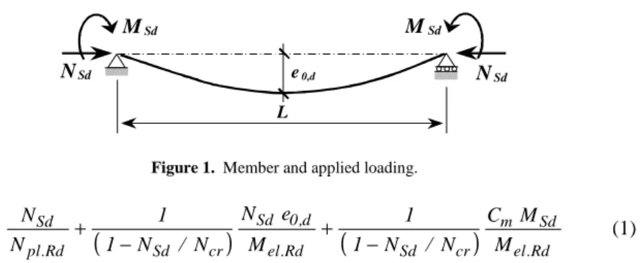
Fig. 1 shows a simply supported member with an initial sinusoidal transverse deformation e0,d, subjected to axial compression NSd and in-plane end-moment distribution MSd. Notations are the same as in Eurocode 3.
NSd NSd
L e0,d
MSd MSd
Figure 1. Member and applied loading.
(
)
(
)
el.Rd Sd m cr Sd Rd . el d , 0 Sd cr Sd Rd . pl Sd M M C N / N 1 1 M e N N / N 1 1 N N − + − + (1)An elastic second-order resistance verification of such a member may be written as in Eq. (1), after having introduced two notions: the equivalent moment factor
m
C , and the second-order amplification factor 1/(1−NSd /Ncr). The equivalent moment factor concept can be defined as follows: “the equivalent moment is the first order constant moment which can be applied to the member already subjected to axial compression in order to obtain the same maximum amplified moment than in the member subjected to the same axial force and to the actual bending distribution”. It can be illustrated by Fig. 2. An additional resistance check has to be done when the axial force is not sufficient to reach a maximum second-order moment in span; this often occurs for members subjected to highly variable linear end-moments along the length of the beam, and in this case, the resistant moment value is reached at an end section, where the resistance has therefore to be checked.
The second important concept lies in the definition of the second-order amplification factor. In order to get the theoretical but anyway simple format of Eq. (1), it is necessary to approximate the amplification factor for constant bending
moment / )
2 (cos /
1 π NSd Ncr by the sinusoidal bending moment one:
) / 1 ( /
1 −NSd Ncr [2]. The definition of C suggested later in this paper is such m
NSd Mmax MSd ΨMSd Me = CmMSd NSd Mmax Me = CmMSd
Actual moment distribution Equivalent moment distribution
Figure 2. Equivalent moment factor concept.
Eq. (1) is the basic formula of the proposal from which all other derivations are made. Starting from it, and remembering that in the particular case of flexural buckling under pure compression, the collapse is reached for NSd =χNpl.Rd, it is then possible to express:
(
)
(
)
Rd pl Rd el cr Rd pl d N M N N e . . . , 0 / 1 1 χ χ χ − − = (2)and then to write Eq. (1) under some other well-known formats. Simple calculations lead to the formulation of [3]:
(
)
1 / 1 . . * + − ≤ Rd el cr Sd Sd m Rd pl Sd M N N M C N N χ (3) where:(
)
(
)
(
Sd cr)
cr Rd pl N N N N / 1 / 1 1 / 1 1 1 . * − − − + = χ χ χ (4)Eq. (1) can also be written as in DIN 18800 format [4]:
n M M C N N Rd el Sd m Rd pl Sd + ≤1−∆ . . χ (5) where: 2 2 . . 1 χ λ χ − = ∆ Rd pl Sd Rd pl Sd N N N N n (6)
(
)
1 / 1 . . ≤ − + Rd el cr Sd Sd m Rd pl Sd M N N M C N N µ χ (7) where: µ=(
1−NSd / Ncr) (
/ 1−χ NSd / Ncr)
(8)This last shape is the one retained for the proposal detailed in this paper, in order to keep the 1/(1−NSd /Ncr) amplification factor and to have a first term as in EC3 buckling check, for pointing out the continuity with pure buckling.
2. 2. Proposed Formulae
For in-plane instability, the proposed formula is expressed as:
(
)
1 M k N / N 1 M C N N Rd cr Sd Sd m Rd . pl Sd ≤ − +µ χ (9)where µ defines as in (8). Ncr is the eulerian critical buckling load, and C is the m
equivalent moment factor [3]:
For linear Mψ moments: Cm
( )
ψ =0,79+0,21ψ +0,36(
ψ −0,33)
NSd /Ncr (10)and for other MQ and MQ+Mψ moments:
cr Sd 2 0 0 2 m N N 1 L M f EI 1 C − + = π (11)
Keeping the term MRd in the relationship allows the formulation to be general, whatever the class of cross-section is. The k coefficient is aimed at correcting the
theoretical elastic shape in order to account for the N−M plastic interaction:
(
w)
Cm Cm(
NSd NplRd)
k 1 2 1 1 2 / . − − − + = λ λ (12)It has been built so that the theoretical elastic format can be kept, and must also be bounded by 1/w=Wel /Wpl for Class 1 or 2 cross-sections, in order the bending moment resistant term kMRd not to be lower than the elastic one. It is also limited by Wel /W3 for Class 3 cross-sections, W being an intermediate plasticity 3
physically but not in Eurocode 3 [5]. In expression (12),
(
w−1)
represents the maximum available bending potential due to plasticity effects. This term must also be tempered by a function of C , because the member cannot develop the same mplasticity effects whatever the transverse loading is, and by a function of the length of the beam, in order to make the behaviour of the beam becoming elastic when slenderness and axial force increase. Then, this calibrated coefficient allows the behaviour of the member to tend in a continuous way from plasticity to pure elasticity when length and axial force increase.
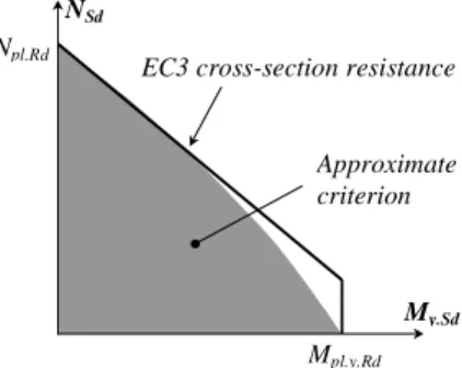
Expression (9) is consistent with the EC3 buckling formulae (M →0), and with the in-plane bending check (N→0). It also reduces to a section resistance criterion, as L→0, that accounts for N−M plastic interaction (Fig. 3).
My.Sd NSd
Npl.Rd
Mpl.y.Rd EC3 cross-section resistance
Approximate criterion
Figure 3. N−Mplastic cross-section interaction (IPE section).
3. Spatial Behaviour
In this paper, only beams prevented from lateral torsional buckling are studied; a formulation where lateral buckling is considered is also available but is not presented here. Anyway the interested reader will find all details about this item in [5]. The in-plane formula of Eq. (1) is extended to biaxial behaviour using two formulae, one for each plane where the collapse is expected to be reached, as it is done in Eurocode 3 for buckling:
(
)
(
)
− + − + Rd . z yz z . cr Sd Sd . z z . m Rd . y yy y . cr Sd Sd . y y . m y Rd . pl y Sd M k N / N 1 M C * M k N / N 1 M C N N µ α χ (13)(
)
(
)
− + − + Rd . z zz z . cr Sd Sd . z z . m Rd . y zy y . cr Sd Sd . y y . m z Rd . pl z Sd M k N / N 1 M C M k N / N 1 M C * N N µ α χ (14)At this stage, the linear interaction formats adopted in Eqs. (13) and (14) are breaking with the full theoretical approach detailed in § 2.1: as a matter of fact, the initial deformations in planes y-y and z-z don’t allow the two amplification factors (one in y-y plane and another in z-z plane) to increase separately with the axial force, as the formulae mean. In reality, a coupling between y-y and z-z instabilities exists, but neglecting its effect doesn’t alter significantly the accuracy of the proposal, while it brings great simplification. The kyy and k coefficients keep the zz
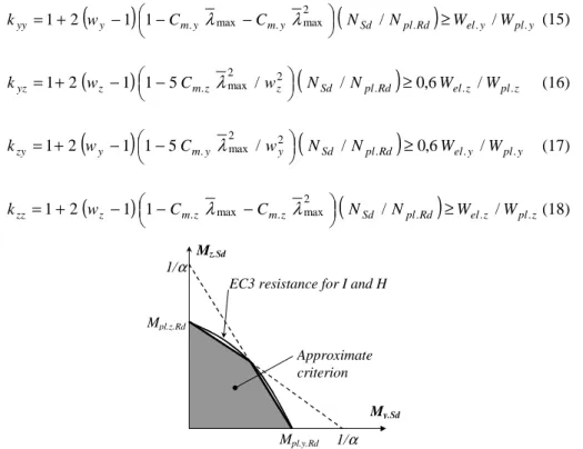
format given in § 2.2, for continuity aspects: indeed, their expression is so that formulae (13) and (14) reduce to plane Eq. (9) when one of the bending moments tends to 0. The only restriction lies in the use of λmax: the latter must be considered in case of spatial behaviour, because the axis of higher slenderness directly governs the ability of the beam to develop any plasticity; full consistency with the buckling formulae of Eurocode 3 can also be exhibited. The kyz and kzy calibrated coefficients reflect the possibility of developing plasticity respectively about weak and strong axis, in formulae (13) and (14) concerning Class 1 or 2 cross-sections:
(
y)
my my(
Sd plRd)
ely ply yy w C C N N W W k . . . 2 max . max . / / 1 1 2 1 ≥ − − − + = λ λ (15)(
z)
mz z(
Sd plRd)
elz plz yz w C w N N W W k 1 2 1 1 5 . 2max / 2 / . ≥0,6 . / . − − + = λ (16)(
y)
my y(
Sd plRd)
ely ply zy w C w N N W W k 1 2 1 1 5 . 2max / 2 / . ≥0,6 . / . − − + = λ (17)(
z)
mz mz(
Sd plRd)
elz plz zz w C C N N W W k 1 2 1 1 . max . 2max / . ≥ . / . − − − + = λ λ (18) My.Sd Mz.Sd Mpl.z.Rd Mpl.y.Rd 1/α 1/α Approximate criterion EC3 resistance for I and Hsections
The last coefficient α* is useful to deal with plasticity interaction between the two bending moments; it is taken equal to 0.6 for Class 1 or 2 cross-sections, and to 1.0 for Class 3 cross-sections. Its value was derived to approximate the Eurocode 3 biaxial bending criterion using two straight lines (Fig. 4). The elastic conservative value of 1.0 represents a linear interaction.
4. Comparison with Numerical Simulations Results
To check its accuracy, the proposal (including the formula with lateral torsional buckling) was compared to about 15 000 numerical FEM simulation results [6], where a large amount of cases were studied, distinguishing the type of: cross-section (IPE 200, IPE 500, HEB 300 and RHS 200×100×10), slenderness, first order bending moment diagram, and kind of behaviour (in-plane y-y, in-plane z-z, and spatial with and without lateral torsional buckling).
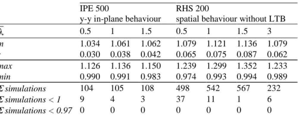
Table 1. Comparison with results of numerical simulations.
IPE 500
y-y in-plane behaviour
RHS 200
spatial behaviour without LTB
λ 0.5 1 1.5 0.5 1 1.5 3 m 1.034 1.061 1.062 1.079 1.121 1.136 1.079 s 0.030 0.038 0.042 0.065 0.075 0.087 0.062 max 1.126 1.136 1.150 1.239 1.299 1.352 1.233 min 0.990 0.991 0.983 0.974 0.993 0.994 0.989 Σ simulations 104 105 108 498 542 567 232 Σ simulations < 1 9 4 3 37 11 1 6 Σ simulations < 0.97 0 0 0 0 0 0 0 The numerical simulations were used to calibrate the k coefficients; some results of
this study [5] are reported in Table 1. The characteristic value used for this comparison is Rsimul =Fsimulation /Fproposal, where F represents one of N, My or
z
M value. In this study, the Rsimul value is the ratio between the ultimate loading of the simulation and the calculated proportional loading giving failure according to the proposal. So, a value Rsimul >1 means that the proposal is safe. It has been seen in 2.1 that an additional resistance check for the end sections needs to be performed, and, when the collapse is reached by excess of plasticity at these particular sections, it becomes the governing criterion. The one retained in this study is so that it sometimes leads to slightly unsafe results, that cannot be objected to the stability formulae. In this way, an additional line in Table 1 represents the
97 . 0
≤ simul
R values, which are really caused by the stability check. As a conclusion, it appears that the formulae give safe results, and are highly satisfactory for plane behaviour, and quite satisfactory for spatial behaviour (without lateral torsional buckling).
5. Conclusion
New formulae for beam-columns are presented in this paper. They are based on elastic second-order theory, and extended to spatial behaviour and to plasticity. While keeping a strong physical meaning, they allow full continuity between the cross-section classes, smooth transitions from plasticity to elasticity when slenderness and axial force increase, and also reduces to resistance checks when the slenderness of the member decreases or the axial force vanishes. Their accuracy has been shown through a comparison study with a large number of numerical simulations emphasising the efficiency of the proposal in representing the behaviour of structural members.
References
1. EC3, Eurocode 3: Design of steel structures. Part 1-1, General rules and rules for buildings, ENV 1993-1-1 (1993).
2. Villette M., Considérations sur le flambement. Proposition de révision de
l’Eurocode 3, Construction Métallique n°3 (1997), 15-38.
3. Bureau A., Galéa Y., Jaspart J.P., Maquoi R., Muzeau J.P. and Villette M.,
Proposal for a revision of Eurocode 3, TC8-ECCS meeting, Timisoara (1999).
4. DIN 18800, Stahlbauten; Bemessung und Konstruktion, Part 1&2 (1990). 5. Boissonnade N., Jaspart J.P., Muzeau J.P. and Villette M., Background
document for the derivation of the beam-column interaction formulae, internal
report, Département MSM-University of Liège, LERMES-Blaise Pascal University, Clermont-Ferrand, Baudin-Châteauneuf Company, Tours (2000). 6. Ofner R., Traglasten von Stäben aus Stahl bei Druck und Biegung , Institut für
Stahlbau, Holzbau und Flächentragwerke, Technische Universität Graz, Fakultät für Bauingenieurwesen, (1997).
Acknowledgements
The authors wish to thank sincerely Prof. R. Greiner, TU Graz (Austria) for his valuable contribution to this proposal and all the other members of the ad-hoc working group: Dr. G. Salzgeber, Dr. R. Ofner (TU Graz), Prof. R. Maquoi (MSM, Univ. of Liège) and Y. Galéa and A. Bureau (CTICM, France).