HAL Id: hal-00348524
https://hal.archives-ouvertes.fr/hal-00348524
Submitted on 5 Jun 2019
HAL is a multi-disciplinary open access
archive for the deposit and dissemination of
sci-entific research documents, whether they are
pub-lished or not. The documents may come from
teaching and research institutions in France or
abroad, or from public or private research centers.
L’archive ouverte pluridisciplinaire HAL, est
destinée au dépôt et à la diffusion de documents
scientifiques de niveau recherche, publiés ou non,
émanant des établissements d’enseignement et de
recherche français ou étrangers, des laboratoires
publics ou privés.
Performances and Potentialities of a very simple
self-compensated pressure sensor demonstrator
Philippe Menini, G. Blasquez, Patrick Pons, X. Chauffleur, Philippe Dondon,
Christian Zardini
To cite this version:
Philippe Menini, G. Blasquez, Patrick Pons, X. Chauffleur, Philippe Dondon, et al.. Performances
and Potentialities of a very simple self-compensated pressure sensor demonstrator. IEEE Transactions
on Instrumentation and Measurement, Institute of Electrical and Electronics Engineers, 1999, VOL
48 (6), pp 1125-1130. �hal-00348524�
Performances and Potentialities of a Very Simple
Self-Compensated Pressure Sensor Demonstrator
P. M´enini, G. Blasquez, P. Pons, X. Chauffleur, P. Dondon, and C. Zardini
Abstract— A pressure sensor demonstrator has been designed and mounted using a simple analog-digital BiCMOS converter and a capacitive Silicon–Pyrex sensing cell. The measurements as a function of pressure and temperature have enabled to evaluate the efficiency of a ratiometric scheme to self-compensate thermal drifts and nonlinearities. The best demonstrator is char-acterized by a thermal coefficient of the offset smaller than 20 ppm/K and a nonlinearity lower than or equal to 61:2% FS. The essential features of the sensor have been modeled by a simple analytical expression. The model specifies the potential gains in pressure sensitivity and nonlinearity. The best design is based on a quasisymmetrical architecture in which stray capacitors are minimized. This study demonstrates the feasibility of self-compensated capacitive sensors characterized by an overall accuracy in the order of a few percents of the measurement scale over a temperature range of 100 K at very low cost.
Index Terms— Capacitance measurement, capacitance trans-ducers, circuit modeling, compensation, nonlinearities, pressure measurement, thermal factors, sensors.
I. INTRODUCTION
T
HE development of cost effective digital systems requires the concomitant development of digital sensors. A simple solution consists in using variable oscillators coupled with counters. In addition, this solution allows the use of sens-ing capacitors that are almost insensitive to temperature and relatively easy to produce.In accurate sensors, the thermal drift [1] and the non-linearities [2] are compensated. Conventional techniques of compensation turn out to be efficient but expensive. Their use should be limited to the cases in which a very high level of accuracy along with an excellent thermal stability are required. In all other cases, it is very often preferable to favor collective compensation techniques and in particular, operating principles and sensing architectures offering self-compensation capabilities. Of course, both approaches are not mutually ex-clusive but rather complementary because self-compensation can only be partial.
In what follows, a capacitive pressure sensor demonstrator based on a digital ratiometric principle is presented. This mock-up has been designed to yield a high value of self-compensation for physical and thermal drifts. It has been mounted using a pair of oscillators and integrated counters
Manuscript received February 18, 1997; revised August 30, 1999. This work was supported by the Eureka/Prometheus European Program.
P. M´enini, G. Blasquez, P. Pons, X. Chauffleur, and C. Zardini are with CNRS/LAAS, 31077 Toulouse, France.
which were fabricated with a 2- m BiCMOS technology in order to obtain a fast response and an excellent matching of their electrical and thermal characteristics.
II. SENSOR DESCRIPTION A. Sensing Capacitor [3], [4]
Basically it is a miniature variable capacitor [1], [2]. Its main constituents are a silicon diaphragm and a metal plate deposited on a rigid Pyrex 7740 substrate. The Silicon and Pyrex are bonded by means of anodic welding. This type of cells presents a high pressure sensitivity, an excellent long term stability and can withstand elevated overpressures [5]–[8]. The specimen used to implement the sensor demonstrator has a capacitance in the order of 34 pF at rest.
The normalized pressure response for pressures between 0.1 and 0.6 MPa and for temperatures varying from 293 K to 363 K is shown in Fig. 1. Clearly, the behavior in this operating range is almost linear. With respect to a linear model computed using the least squares curve fitting, the nonlinearities expressed in percentage of the measurement scale are in the 2.5% range.
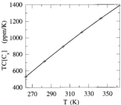
The thermal behavior of the sensing cell from 293 K to 363 K is detailed in Fig. 2. The incremental thermal coeffi-cient decreases as the temperature or the pressure increases. Nevertheless its magnitude remains in the interval [ 30 ppm/K, 40 ppm/K].
Uncertainties (due to the finite accuracy of the measurement set up) in Figs. 1and 2 are lower or equal to 3 ppm and 2 ppm/K, respectively.
B. Analog–Digital BiCMOS Converter [9]
This converter has been designed to generate a digital output inversely proportional to . This transformation aims to obtain a response more linear than those of the sensing cell [2], [5]. Physically, it is an integrated circuit which essentially includes an oscillator and a digital counter. The oscillator generates a triangular waveform. It operates on the principle of the charge and the discharge of capacitors, with a constant current , between two constant voltage thresholds [9], [10] defined by two fast comparators.
The period of an oscillator of this type connected to can be described by the following expression:
(1) if the delay due to the comparators is negligible.
Fig. 1. Normalized response of the sensing cell; measurements carried out at 263 K(1) and 363 K(o).
Fig. 2. Incremental thermal coefficient of the sensing cell in the range 0.1 to 0.6 MPaTC[Cm] = @Cm=(Cm@T ).
Fig. 3. Incremental thermal coefficient of the oscillator frequency
(Fm= m01); measurements carried out with a ceramic capacitor of 34 pF.
By design, A and the peak-to-peak amplitude of the oscillations is equal to 1.2 V.
Within any time interval , the digital counter output is given by
(2) Fig. 3 shows the incremental thermal coefficient of the os-cillator frequency . It is rather significant. Complementary tests have indicated that the most part of the thermal drift arises from current sources.
C. Ratiometric Implementation
The block diagram shown in Fig. 4 includes two A/D con-verters connected to the capacitors and , respectively. stands for the sensing cell and for a constant reference capacitor.
Fig. 4. Block diagram of the pressure sensor: triangular oscillator (T.O.), digital counter (D.C.), and control logic (C.L.).
If both digital counters are triggered at the same time and if the counting duration is sufficient, it may be admitted that
(3) where and are the digital output and the period of the converter connected to , respectively. The logic block interrupts the counting operations as soon as reaches a preset value which has to be sufficiently large to filter possible random fluctuations of and . These fluctuations include circuit noises and electromagnetic interferences between the analog and digital blocks of the converters.
In the ideal case where both converters are identical, the response derived from (1) and (3) is given by
(4) This relationship being independent of and , their drifts (if any) have no impact on the response. In the more realistic case of circuits exhibiting slightly different characteristics, the variations of should be very small.
III. SENSOR CHARACTERIZATION
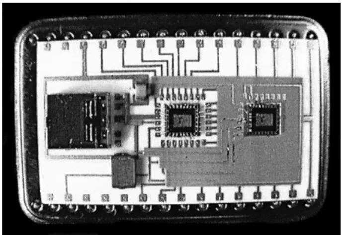
In order to identify the primary parameters determining the sensor behavior, several versions of the demonstrator were implemented and tested. The basic platform is shown in Fig. 5. In what follows, the most instructive results are reported. They will be interpreted in Section IV.
A. Four-Chip Implementation
This mock-up results from the assembly of two sensing ca-pacitors and two distinct converters (biasing conditions
V, mA) implemented with a 2- m BiCMOS process (STKM 2000 technology, Comparator switching delay 90 ns). Pressure is only applied to one of the sensing cells, the other being used as a reference capacitor. This implementation permits a thorough insulation of both oscillators, thereby avoiding the risks of synchronization. In addition, as the devices are matched, they should offer a high level of self-compensation.
Fig. 6 shows the ratio between 0.1 and 0.6 MPa for temperatures between 263 K and 363 K. Irrespective of temperature, the response is almost linear. The nonlinearity is situated in the range 1.2% FS. As expected, it is signifi-cantly less than that of the sensing cell. Nevertheless, it is not as low as computed in [5]. This observation will be discussed in Section IV.
MENINI et al.: PRESSURE SENSOR DEMONSTRATOR
In agreement with (4), it is also observed in Fig. 6 that the normalized response displays a small dependence on temperature even though the thermal drift of oscillators is substantial. The attenuation given by the ratiometric design is specified in Fig. 7. Its maximum value reaches 60 at 363 K. Consequently, the ratiometric design implemented with the BiCMOS technology procures a high level of self-compensation of the offset thermal drift.
Finally these features were achieved with . Assuming an error of 1 bit the resolution on is in the order of .
B. Semi-Integrated Sensor
This mock-up has been mounted using two converters integrated into the same chip, a Silicon–Pyrex sensing cell and a ceramic capacitor. It has been assembled in order to obtain the best possible “matching” of converters and to assess the feasibility of integration. Tests have shown a very high level of noise due to a random synchronization of the triangular oscillators when and are similar. This problem has been solved by increasing .
The results presented in the Fig. 8 have been obtained with pF, and measured in the same pressure and temperature conditions as in Section III-A. Their analysis leads to the following observations. First, the normalized response is lower than expected from (4). Secondly the influence of temperature on the offset is greater than the evaluation carried out from the data in Fig. 6 and (4).
IV. DISCUSSION A. Modeling
The triangular oscillators of the converters include current sources, comparators, MOST switches and their intercon-nections. Their physical capacitors are equivalent to a stray capacitor connected in parallel to and . The simplest model for the demonstrator normalized response, including the effects of , is therefore given by
(5) The evaluation of from (5) and the data in Figs. 6 and 8 yields pF.
B. Influence of on Pressure Sensitivity and Linearity
Let and be the respective sensitivities of the sensing cell and the sensor. Differentiating (5) with respect to , we obtain
(6)
where and .
If the derivative of with respect to is positive. This implies
. In Sections III-A and B, the conditions and are fulfilled. Consequently provokes
Fig. 5. Evaluation platform composed of integrated analog–digital BiCMOS converters, ceramic capacitors, and a sensing cell on a ceramic substrate.
Fig. 6. Normalized response of the four chips mock-up; measurements carried out at 263 K(+) and 363 K(o). An inactive sensing cell is used as a reference capacitor.
Fig. 7. Ratio of the incremental thermal coefficients of the oscillator and the sensor output forP = 0 versus temperature.
the decrease of pressure sensitivity reported in Sections III-A and B. The loss of sensitivity defined by
% (7)
is given in Fig. 9 as a function of the ratio and for . In our case as pF and pF, Fig. 9 indicates a loss of pressure sensitivity close to 25%. This estimation is consistent with data in Figs. 1 and 6 since
% and %.
Fig. 10 illustrates the influence of on the nonlinearity. For pF, this evaluation derived from (5) gives
Fig. 8. Normalized response of the semi-integrated demonstrator. Measure-ments carried out at 263 K(+) and 363 K(o). A ceramic capacitor (Cr= 265 pF) is used as a reference capacitor.
Fig. 9. Loss in pressure sensitivity versusCs=Cm.
Fig. 10. Maximum nonlinearity versus Cs=Cm.
a nonlinearity lower than 1.25%. Measurements reported in Section III-A lead to a nonlinearity of 1.2%.
C. Analysis of the Thermal Behavior
In what follows, it is assumed that depends on tempera-ture. To begin with, let us derive from (5) the expression of the incremental thermal coefficient of the offset. By differentiating (5) with respect to , for , and by neglecting for clarity the dependence of and on , we get
(8)
where , and .
If , the incremental temperature coefficient is almost equal to zero. In this case, the model predicts a low offset drift. On the other hand, for , the model
Fig. 11. Incremental thermal coefficient of stray capacitors.
predicts an offset drift proportional to the thermal drift of stray capacitors.
Figs. 6 and 8 respectively validate the model for
and reveal a strong dependence of on temperature. The estimation of the incremental thermal coefficient of from the experimental data yields the curve shown in Fig. 11. These high values can only originate from the comparators input admittances and, to a lesser degree, from the PN junction ca-pacitances associated with the transistors of the current sources and analog switches. The comparators used to fabricate the demonstrator have NPN bipolar transistors at the input. This choice has been made in order to minimize the nonlinearity [9] due to finite switching times.
For completeness, let us analyze the effect of on the thermal drift of . By differentiating (6) with respect to we obtain
(9) If for any , (9) is reduced to
(10) Recalling that and , (10) shows that gives a significant contribution to the thermal drift of the pressure sensitivity of the demonstrator. In addition, (10) specifies that there is no self-compensation for .
D. Potential Developments
From the previous considerations, it appears that this demonstrator can be improved. To do so, one has to minimize stray capacitors and more particularly those of the converter. The easiest improvement consists in replacing the comparators using NPN bipolar transistors at the input by NMOS input comparators. This change should divide by two or even by three the present value of and dramatically reduce the value of . In this case, the last term of (10) would become marginal and the thermal sensitivity of would be almost fully determined by that of the sensing cell. As an additional benefit, the pressure sensitivity would be increased by more than 10% and nonlinearity would be decreased in similar proportions as shown in Figs. 9 and 10.
MENINI et al.: PRESSURE SENSOR DEMONSTRATOR
Moreover the implementation of the converter with submi-cron technologies such as the STKM 4000 process (or any equivalent and validated technology) should approximately divide by 3 the switching delay of the comparators. Demon-strators fabricated from converters of this type, should offer operating frequencies equal or greater than 10 MHz.
V. CONCLUSION
A capacitive pressure sensor demonstrator has been de-signed, implemented and characterized in order to evaluate the feasibility of inexpensive, versatile and accurate sensors that could be easily produced. By design, this sensor features a simple architecture and delivers a digital output. The lineariza-tion of the response and the thermal compensalineariza-tion rely on a ratiometric principle. Finally, through numerical integration, it can filter pressure fluctuations and electric noise.
Two implementations of the demonstrator have been done using a BiCMOS converter and sensing cells whose de-formable plates are made of silicon. Evaluation tests have been carried out with a biasing voltage of 5 V from 263 K to 363 K. The best demonstrator features a nonlinearity of 1.2% of the measurement scale and an offset drift of 20 ppm/K.
The analysis of the influence of stray capacitors has enabled us to specify the loss of pressure sensitivity and linearity. Additionally, it has shown that the fast BiCMOS comparators determine, to a great extent, the magnitude of the thermal drift of the pressure sensitivity. By replacing these devices by NMOS input comparators, the pressure sensitivity thermal drift should reduce to that of the sensing cell and improve linearity and pressure sensitivity.
This study demonstrates the feasibility of sensors charac-terized by an accuracy in the order of a few percents of the measurement scale without thermal compensation and using a BiCMOS technology. The implementation of the converter with a MOS technology seems to be possible. Submicron technologies should offer in addition operating frequencies equal or greater than 10 MHz. From (1) it is obvious that high operating frequencies allow the use of subminiature sensing cells characterized by capacitances of a few picofarads. For sensing cells having capacitances smaller than a few pF at rest, more refined converters are required. The capacitive sensor interface described in [11] seems to be well adapted to these cases.
The modular architecture of the demonstrator allows the development of a family of pressure sensors using a common converter and a series of sensing cells. The pressure operating range can be simply determined by adjusting the diaphragm thickness. The feasibility of sensing cell demonstrators in the pressure range Mpa, 2.7 Mpa has been demonstrated. Finally the potential application domain of these sensors is therefore very diversified as stated in [12].
ACKNOWLEDGMENT
The authors would like to thank A. Coustre, F. Garajedagui, P. Saint Martin, D. Esteve, J. L. Aucouturier, and B. H¨offlinger for their encouragement.
REFERENCES
[1] F. V. Schnatz, U. Sch¨oneberg, W. Brockherde, P. Kopystynski, T. Mehlhorn, E. Obermeier, and H. Benzel, “Smart CMOS capacitive pressure transducer with on-chip calibration capability,” Sens. Actuators
A, vol. 34, pp. 77–83, 1992.
[2] B. Puers, E. Peeters, A. van den Bossche, and W. Sansen, “A capacitive pressure sensor with low impedance output and active suppression of parasitic effects,” Sens. Actuators A, vol. 21–23, pp. 108–114, 1990. [3] Y. S. Lee and K. D. Wise, “A batch-fabricated silicon capacitive pressure
sensor with low temperature sensitivity,” IEEE Trans. Electron Devices, vol. ED-29, pp. 42–48, 1982.
[4] G. Blasquez, Y. Naciri, P. Blondel, N. E. B. Moussa, and P. Pons, “Micromachined silicon capacitive sensor,” in Proc. 2nd Int. Conf.
Passive Comp. Mater. Tech. Process., Paris, France, Nov. 18–20, 1987,
pp. 142–146.
[5] P. Pons, G. Blasquez, and R. Behocaray, “Feasibility of capacitive pressure sensors without compensation circuit,” Sens. Actuators A, vol. 37–38, pp. 112–115, 1993.
[6] A. Jornod and F. Rudolf, “High precision capacitive absolute pressure sensor,” Sens. Actuators A, vol. 17, pp. 415–421, 1989.
[7] T. Rogers and J. Kowal, “Anodic bonding conditions and material com-patibility for silicon-glass capacitive pressure sensors,” Sens. Actuators
A,, vols. 46–47, pp. 113–120, 1995.
[8] M. J. S. Smith, L. Bowman, and J. D. Meindl, “Design and performance of a capacitive pressure sensor IC,” IEEE Trans. Biomed. Eng., vol. BME-33, no. 2, pp. 163–174, 1986.
[9] P. Dondon, Ch. Zardini, and J. L. Aucouturier, “BiCMOS integrated circuit for capacitive pressure sensors in automotive applications,” Sens.
Actuators A, vols. 37–38, pp. 596–599, 1993.
[10] A. Hanneborg, T. E. Hansen, P. A. Ohlckers, E. Carlson, B. Dahl, and O. Holwech, “An integrated capacitive pressure sensor with frequency-modulated output,” Sens. Actuators A, vol. 9, pp. 345–351, 1986. [11] F. van der Goes and G. Meijer, “A novel low cost capacitive sensor
interface,” IEEE Trans. Instrum. Meas., vol. 45, pp. 536–540, Apr. 1996. [12] S. C. Chang and W. Ko, “Capacitive sensors,” in Mechanical Sensors.
New York: VCH, 1994.
P. Menini was born in Toulouse, France, in 1970.
He received the Ph.D. degree in electronics from the Paul Sabatier University, Toulouse, in 1998. His doctoral studies were concentrated on char-acterization and modeling of capacitive pressure sensors.
Since 1999, he has been an Assistant Professor at Paul Sabatier University. At the same time, he joined the Laboratoire d’Analyze et d’Architecture des Syst`emes du Centre National de Recherche Scientifique (LAAS-CNRS), Toulouse. His research interests includes instrumentation, electrical modeling, and design of MEMS.
G. Blasquez received the “Doctorat d’Etat” degree
in physics from Paul Sabatier University, Toulouse, France, in 1973.
He is now Directeur de Recherche, CNRS, Toulouse. His research expertise lies in semiconduc-tor devices including technology, design, modeling, and characterization.
P. Pons received the Doctorat degree in physics
from Paul Sabatier University, Toulouse, France, in 1990.
He is now Charg´e de Recherche with the CNRS, Toulouse. His research interests are focused in mi-crotechnology and microsensors.
X. Chauffleur received the Ingenieur degree in mechanics from the ENI of
Tarbes, France, in 1991, and the Ph.D. degree in electronics from Paul Sabatier University, Toulouse, France, in 1998. His doctoral studies concerned the modeling of mechatronics sensors by means of finite element analysis.
Since 1998, he has been with the EPSILON Company, Toulouse, working on thermal, thermomechanical modeling, and reliability analysis of electronic equipment. He also participates in the development of the thermal modeling software REBECA-3D based on BEM.
P. Dondon received the Diploma degree in electronic engineering from the
Ecole Nationale Sup´erieure d’Electronique et de Radio´electricit´e, Bordeaux, France, in 1983. He received the Ph.D. degree from IXL Bordeaux in 1993.
He was with the T´elecommunications Radio´electriques et T´el´ephoniques Company for six years as Product Manager working on analog radio links manufacturing lines. He is now teaching in the Bordeaux University.
C. Zardini received the Doctoral degree in electronics from the University
of Montpellier, Montpellier, France, in 1982.
He is presently a Professor of electrical engineering at the Ecole Nationale Sup´erieure d’Electronique et de Radio´electricit´e, Bordeaux, France. His cur-rent research work is in the area of hybrid power circuits and high frequency power conversion.
![Fig. 2. Incremental thermal coefficient of the sensing cell in the range 0.1 to 0.6 MPa TC[C m ] = @C m =(C m @T ).](https://thumb-eu.123doks.com/thumbv2/123doknet/2354593.37230/3.918.149.353.80.259/fig-incremental-thermal-coefficient-sensing-cell-range-mpa.webp)